5 | kinovarobotics.com
KINOVA
®
Gen3
Ultra lightweight
robot
User Guide
Contents
Introduction.............................................................................................................................................................. 1
Welcome.................................................................................................................................................................... 1
Intended domains of application......................................................................................................................1
About this document.............................................................................................................................................1
Acronyms and abbreviations............................................................................................................................. 1
Warranty...................................................................................................................................................................4
EU Declaration of Incorporation...................................................................................................................... 4
FCC Declaration of Comformity........................................................................................................................6
Safety directives and warnings........................................................................................................................ 7
Disclaimer...............................................................................................................................................................10
Risk assessment.................................................................................................................................................. 10
Normal use definition......................................................................................................................................... 11
Applicable firmware and API versions..........................................................................................................11
Robot components............................................................................................................................................... 13
Overview..................................................................................................................................................................13
Base.......................................................................................................................................................................... 14
Quick connect base..................................................................................................................................15
Fixed base...................................................................................................................................................16
Base connector panel.............................................................................................................................17
Base mounting interface.......................................................................................................................18
Actuators................................................................................................................................................................20
Interface module.................................................................................................................................................20
Vision module....................................................................................................................................................... 23
Robot communications and network interfaces......................................................................................25
Getting started......................................................................................................................................................27
Overview.................................................................................................................................................................27
What's in the case?............................................................................................................................................ 27
Manipulating the robot joints when the robot is powered o............................................................29
Robot mounting options...................................................................................................................................29
Mounting the robot on a tabletop with mounting plate and table clamp........................... 29
Mounting the robot on a horizontal surface without the table clamp................................. 32
Mounting plate bolting pattern..........................................................................................................33
Base mounting interface bolting pattern.......................................................................................34
Mounting the robot on a wall or ceiling......................................................................................... 35
Robot power adapter and E-stop................................................................................................................. 38
Powering robot from a battery via a custom wiring harness............................................................. 38
Powering on the robot...................................................................................................................................... 39
Power-up, booting, and initialization sequence.......................................................................................40
Resetting the robot to factory settings.......................................................................................................41
Operating the robot............................................................................................................................................ 41
Overview of operating the robot........................................................................................................41
Supported control devices................................................................................................................... 41
Home and retract positions................................................................................................................. 51
Putting the robot into admittance using the interface buttons...............................................51
Connecting a computer to the robot............................................................................................................52
Connection options................................................................................................................................. 52
Connecting a computer to the robot via Ethernet (for the first time)................................... 53
Kinova® Kortex™ Web App.................................................................................................................. 55
Changing the robot wired connection IP address and connecting the robot to a
LAN.......................................................................................................................................................... 57
Connecting a computer to the robot via Wi-Fi............................................................................. 58
Assigning a static IP address for Wi-Fi to the robot...................................................................59
Dimensions, specifications, and capabilities...............................................................................................61
Schematic and dimensions - 7 DoF spherical wrist................................................................................ 61
Schematic and dimensions - 6 DoF spherical wrist............................................................................... 62
Technical Specifications....................................................................................................................................63
Sensors................................................................................................................................................................... 66
Eective workspace........................................................................................................................................... 67
Payload vs. workspace......................................................................................................................................69
Wrist interface, tool expansion, and vision.................................................................................................70
Interface module expansion - tips for installing tools..........................................................................70
End eector reference design............................................................................................................. 71
Removing end cap from the interface module............................................................................. 74
Robotiq Adaptive Grippers installation (optional)....................................................................... 75
Robotiq 2F-85 and 2F-140 Gripper default configuration settings reference.................... 79
Interface module bolting pattern......................................................................................................80
Interface module user expansion connector pinout.................................................................. 80
Using interface module expansion to control devices via API................................................ 82
Spring-loaded connector pinout........................................................................................................82
Accessing Vision module color and depth streams................................................................................83
Concepts and terminology................................................................................................................................85
Robot key concepts and terminology.......................................................................................................... 85
Robot control........................................................................................................................................................ 92
High-level and low-level robot control...................................................................................................... 92
High-level and low-level robot control methods reference................................................................92
Control features...................................................................................................................................................95
Singularity avoidance.............................................................................................................................95
Protection zones......................................................................................................................................96
Joint limits..................................................................................................................................................97
Cartesian limits...................................................................................................................................... 100
Configurable limits................................................................................................................................100
High-level control modes description........................................................................................................101
Trajectory control modes................................................................................................................... 102
Joystick control modes........................................................................................................................103
Admittance modes................................................................................................................................104
Force Control modes............................................................................................................................104
Low-level control detailed description..................................................................................................... 105
Low-level control implementation................................................................................................. 105
Low-level feedback.............................................................................................................................. 106
Low-level commands...........................................................................................................................109
Waypoint trajectories.......................................................................................................................................110
Angular waypoints.................................................................................................................................110
Cartesian waypoints.............................................................................................................................. 111
Validation of a waypoint list...............................................................................................................111
Configurations and safeties............................................................................................................................112
Configurable parameters................................................................................................................................ 112
Control library configuration..............................................................................................................112
Base configuration.................................................................................................................................114
Actuators configuration....................................................................................................................... 115
Interface configuration.........................................................................................................................117
Device configuration..............................................................................................................................117
Vision configuration...............................................................................................................................117
Safety items......................................................................................................................................................... 119
Base safeties........................................................................................................................................... 119
Actuators safeties..................................................................................................................................121
Interface module safeties.................................................................................................................. 123
Kinova® Kortex™ Web App User Guide....................................................................................................... 126
Introduction......................................................................................................................................................... 126
Purpose................................................................................................................................................................. 126
Device availability of Web App.....................................................................................................................126
Platform and browser support.................................................................................................................... 128
User login.............................................................................................................................................................128
Web App layout and navigation...................................................................................................................130
Robot control panel..........................................................................................................................................134
Pose virtual joystick control..............................................................................................................134
Angular virtual joystick control........................................................................................................136
Virtual joystick keyboard shortcuts................................................................................................ 137
Admittance modes panel....................................................................................................................139
Actions panel.......................................................................................................................................... 139
Camera panel.......................................................................................................................................... 139
Snapshot tool..........................................................................................................................................139
Main pages.......................................................................................................................................................... 140
Configurations page group................................................................................................................ 140
Safeties......................................................................................................................................................153
Operations page group........................................................................................................................153
Systems page group.............................................................................................................................167
Users...........................................................................................................................................................173
Kinova® Kortex™ Developer Guide............................................................................................................... 176
Introduction......................................................................................................................................................... 176
Devices and services........................................................................................................................................ 176
Available services.............................................................................................................................................. 177
Services, methods, and messages.............................................................................................................. 178
Kinova
®
Kortex™ API and Google Protocol Buer................................................................................. 178
Service client-server model...........................................................................................................................179
Blocking and non-blocking calls.................................................................................................................. 179
Users, connections and sessions.................................................................................................................179
Device routing and transport....................................................................................................................... 180
Robot servoing modes..................................................................................................................................... 181
High-level servoing............................................................................................................................... 181
Low-level servoing............................................................................................................................... 182
Low-level bypass servoing................................................................................................................182
Notifications........................................................................................................................................................ 183
Error management............................................................................................................................................183
Error codes.............................................................................................................................................. 183
Kinova
®
Kortex™ GitHub repository............................................................................................................187
Kinova
®
Kortex™ ROS packages and GitHub repository overview...................................................188
Kinova
®
Kortex™ MATLAB
®
API and GitHub repository overview....................................................188
Working with camera streams using GStreamer...................................................................................189
Windows command examples......................................................................................................... 189
Linux command examples................................................................................................................. 190
Kinova
®
Kortex™ ROS vision module package and Github overview...............................................190
Guidance for advanced users......................................................................................................................... 191
Overview................................................................................................................................................................191
Reference frames and transformations.................................................................................................... 191
Standard robot frames.........................................................................................................................191
Homogeneous transforms................................................................................................................. 192
Homogeneous transform matrices - 7 DoF spherical wrist................................................... 192
Homogeneous transform matrices - 6 DoF spherical wrist...................................................194
Vision module sensors reference frames.....................................................................................196
Denavit-Hartenberg (DH) parameters............................................................................................197
Denavit-Hartenberg (DH) parameters - 7 DoF spherical wrist............................................. 198
Denavit-Hartenberg (DH) parameters - 6 DoF spherical wrist............................................. 199
7 DoF singular configurations.......................................................................................................................201
6 DoF singular configurations......................................................................................................................202
Inertial parameters definition......................................................................................................................203
Inertial parameters of the 7 DoF robot.................................................................................................... 204
Inertial parameters of the 6 DoF robot.................................................................................................... 207
Maintenance and troubleshooting............................................................................................................... 210
Maintenance........................................................................................................................................................210
Troubleshooting................................................................................................................................................. 212
Base LEDs interpretation....................................................................................................................213
How to respond to safety warnings and errors.........................................................................214
Contacting Kinova support.................................................................................................................216
Harmonized Standards, Declarations and Certificates.......................................................................... 217

Kinova® Gen3 Ultra lightweight robot User Guide 1
Introduction
Welcome
Welcome to the Kinova
®
Gen3 Ultra lightweight robot.
Thank you for choosing our robot as a tool for your applications.
This document is meant to provide you with all the information you need to get up and running with
your new robot and get the most out of it.
We are here to help you in your journey. If you need any help or have any questions about how to
get to where you want to go with the robot, please feel free to contact our support team:
www.kinovarobotics.com/support
Intended domains of application
The robot is intended for specific domains of application.
This product is intended for the research and professional fields.
The robot should not be used as an assistance robot for people with reduced mobility.
The robot can be used for research on assistive tasks as long as no clinical trial is carried out.
About this document
General information about the user guide.
Read all instructions before using this product and any third-party options.
Read all warnings on the product and in this guide.
This document contains information regarding product setup and operation. It is intended for
Kinova product end users.
All third-party product names, logos, and brands appearing herein are the property of their
respective owners and are for identification purposes only. Their use in this document is not meant
to imply endorsement by Kinova.
Kinova has made every effort to ensure that this document is accurate, accessible and complete. As
part of our commitment to continuous improvement, we welcome any comments or suggestions at
www.kinovarobotics.com/support.
From time to time, Kinova will make udpates to this document. To download the most up to date
version of this document, visit the product technical resources page on the Kinova website.
For general inquiries please contact us at +1 (514) 277-3777
Acronyms and abbreviations
API
Application Programming Interface
+1 514-277-3777 kinovarobotics.com
© 2022 Kinova inc. All rights reserved.

Kinova® Gen3 Ultra lightweight robot User Guide 2
CIDR
Classless Inter-Domain Routing
CISPR
Comité International Spécial des Perturbations Radioélectriques
EE
End Effector
EMI
Electromagnetic Interference
FOV
Field of View
fps
frames per second
GPI
General Purpose Input
GPIO
General Purpose Input/Output
HDMI
High-Definition Multimedia Interface
IC
Integrated Circuit
IEEE
Institute of Electrical and Electronics Engineers
I
2
C
Inter-Integrated Circuit (bus)
I/O
Input / Output
IP
Ingress Protection or Internet Protocol
IT
Information Technology
ISO
International Organization for Standardization
+1 514-277-3777 kinovarobotics.com
© 2022 Kinova inc. All rights reserved.

Kinova® Gen3 Ultra lightweight robot User Guide 3
LED
Light-Emitting Diode
NVRAM
Non-Volatile Random-Access Memory
PC
Personal Computer
ROS
Robot Operating System
RPC
Remote Procedure Call
RPM
Revolutions Per Minute
RS
Recommended Standard
Rx
Receiver
SSID
Service Set IDentifier
TCP
Transmission Control Protocol
Tx
Transmitter
UART
Universal Asynchronous Receiver-Transmitter
UDP
User Datagram Protocol
USB
Universal Serial Bus
UL
Underwriters Laboratory
UV
Ultraviolet light
+1 514-277-3777 kinovarobotics.com
© 2022 Kinova inc. All rights reserved.

Kinova® Gen3 Ultra lightweight robot User Guide 4
VLAN
Virtual Local Area Network
WEEE
Waste of Electrical and Electronic Equipment
Warranty
This section describes the Kinova warranty terms.
Subject to the terms of this clause, Kinova warrants to End User that the Products are free of
defects in materials and workmanship that materially affect their performance for a period of two
(2) years from the date Kinova ships the Products to the End User ("Delivery Date").
Kinova agrees to repair or replace (at Kinova's option) all Products which fail to conform to the
relevant warranty provided that:
1. notification of the defect is received by Kinova within the warranty period specified above;
2. allegedly defective Products are returned to Kinova, (at the End User’s expense, with Kinova's
prior authorization) within thirty (30) days of the defect becoming apparent;
3. the Products have not been altered, modified or subject to misuse, incorrect installation,
maintenance, neglect, accident or damage caused by excessive current or used with
incompatible parts;
4. the End User is not in default under any of its obligations under this Agreement;
5. replacement Products must have the benefit of the applicable warranty for the remainder of the
applicable warranty period.
If Kinova diligently repairs or replaces the Products in accordance with this section, it will be
deemed to have no further liability for a breach of the relevant warranty.
Allegedly defective Products returned to Kinova in accordance with this contract will, if found by
Kinova on examination not to be defective, be returned to the End User. Kinova may charge a fee
for examination and testing.
The warranty cannot be assigned or transferred and is to the sole benefit of the End User.
Where the Products have been manufactured and supplied to Kinova by a third party, any warranty
granted to Kinova in respect of the Products may be passed on to the End User.
Kinova is entitled in its absolute discretion to refund the price of the defective Products in the
event that such price has already been paid.
EU Declaration of Incorporation
EU Declaration of Incorporation for the robot.
The Declaration of Conformity is a self-declared assessment produced and signed by a
manufacturer of a product to assert that the product meets all of the requirements of the applicable
directives.
In the case of Kinova
®
Gen3 Ultra lightweight robot, the applicable directives that are eligible for CE
declaration are the following:
• Machinery Directive 2006/42/EC
• Electromagnetic Compatibility (EMC) Directive 2014/30/EU
The Machinery Directive 2006/42/EC Article 2 (g) states that:
+1 514-277-3777 kinovarobotics.com
© 2022 Kinova inc. All rights reserved.
Kinova® Gen3 Ultra lightweight robot User Guide 5
‘Partly completed machinery’ means an assembly which is almost machinery but which
cannot in itself perform a specific application. A drive system is partly completed machinery.
Partly completed machinery is only intended to be incorporated into or assembled with other
machinery or other partly completed machinery or equipment, thereby forming machinery
to which this Directive applies; is not eligible to CE marking by its own because it is an
“incomplete machine.”
Based on this definition, our product Gen3 Ultra lightweight robot is considered partly completed
machinery because it has no specific application. The robot application is determined when it is
incorporated in a system, given an and-effector and expected workpieces. Once the product is
incorporated into a complete system and the system complies to all applicable directives, then
the integrator is permitted to issue a Declaration of Conformity and affix the CE marking to the
completed machine. For incomplete machinery, a Declaration of Incorporation (DoI) is required
from the manufacturer. The content of the declaration is also inserted below.
EU DECLARATION OF INCORPORATION (In accordance with ISO/IEC 17050-1:2004)
Manufacturer:
Kinova Robotics
4333 Boulevard de la Grande-Allée,
Boisbriand, QC J7H 1M7, Canada
Telephone: +1 514-277-3777
Manufacturer’s authorized EU representative :
Kinova Europe GmbH
Grosskitzighofer. Str. 7a,
86853 Langerringen
Telephone: +49 8248 8887-928
Description and identification of the partially completed machine(s):
Product and function : Robot (Multi-axis manipulator)
KINOVA
®
Gen3 Ultra lightweight robot L53 0007
Models :
KINOVA
®
Gen3 Ultra lightweight robot L53 0006
KINOVA
®
Gen3 Ultra lightweight robot shall only be put into service upon being integrated into a final
complete machine (robot system, cell or application), which conforms with the provisions of the
Machinery Directive and other applicable Directives.
When this incomplete machine is integrated and becomes a complete machine, the integrator is responsible
for determining that the completed machine fulfils all applicable directives and updating the relevant
harmonized standards, other standards and documents.
It is declared that the above products, for what is supplied, fulfil the following directives as detailed
below:
The following essential health and safety
requirements are applied and fulfilled :
• Machinery Directive 2006/42/EC
1.1.2, 1.1.3, 1.1.5, 1.2.1, 1.2.4.3, 1.2.6, 1.3.4, 1.3.8.1,
1.5.1, 1.5.2, 1.5.6, 1.5.10, 1.6.3, 1.7.2, 1.7.4
• Electromagnetic Compatibility (EMC) Directive
2014/30/EU
The partly completed machinery is also compliant with the following relevant standards:
• IEC 62368-1:2014/AC:2015
Audio/video, information and communication
technology equipment - Part 1: Safety requirements
+1 514-277-3777 kinovarobotics.com
© 2022 Kinova inc. All rights reserved.
Kinova® Gen3 Ultra lightweight robot User Guide 6
• ISO 12100:2010
Safety of machinery - General principles for design -
Risk assessment and risk reduction
• IEC 61000-6-1:2016
Electromagnetic compatibility (EMC) - Part 6-1:
Generic standards - Immunity for residential,
commercial and light-industrial environments
• IEC 61000-6-3:2016
Electromagnetic compatibility (EMC) - Part
6-3: Generic standards - Emission standard
for residential, commercial and light-industrial
environments
The manufacturer or its authorised representative will undertake to transmit, in response to a reasoned
request by the national authorities, relevant information on the partly completed machinery.
The Technical Construction File is kept and maintained at the corporate headquarters of Kinova Robotics
located at 4333 Boulevard de la Grande-Allée, Boisbriand, QC J7H 1M7, Canada.
Boisbriand Canada, 08 August 2019
Louis-Joseph Caron L'Écuyer
Chief Operation Officer & Co-Founder
FCC Declaration of Comformity
FCC Declaration of Conformity for the robot.
FCC Regulatory Disclosures: This equipment has been tested and found to comply with the limits
for a Class B digital device, pursuant to part 15 of the FCC Rules. These limits are designed to
provide reasonable protection against harmful interference in a residential installation. This
equipment generates, uses and can radiate radio frequency energy and, if not installed and used
in accordance with the instructions, may cause harmful interference to radio communications.
However, there is no guarantee that interference will not occur in a particular installation. If
this equipment does cause harmful interference to radio or television reception, which can be
determined by turning the equipment off and on, the user is encouraged to try to correct the
interference by one or more of the following measures:
• Reorient or relocate the receiving antenna
• Increase the separation between the equipment and receiver
• Connect the equipment into an outlet on a circuit different from that to which the receiver is
connected
• Consult the dealer or an experienced radio/TV technician for help
The Declaration of Conformity for the robot is inserted below.
FCC SUPPLIER'S DECLARATION OF CONFORMITY
Manufacturer:
Kinova Robotics
4333 Boulevard de la Grande-Allée,
Boisbriand, QC J7H 1M7, Canada
Telephone: +1 514-277-3777
+1 514-277-3777 kinovarobotics.com
© 2022 Kinova inc. All rights reserved.
Kinova® Gen3 Ultra lightweight robot User Guide 7
Description and identification of the devices:
Product and function : Robot (Multi-axis manipulator)
Models :
KINOVA
®
Gen3 Ultra lightweight robot L53 0007
KINOVA
®
Gen3 Ultra lightweight robot L53 0006
These devices contains the following certified modular transmitter : FCC ID A3LSIP007AFS00
These devices comply with Part 15 of the FCC Rules and Regulations for Information Technology
Equipment :
•
FCC 47 CFR Part 15, Subpart B – Verification
Operation is subject to the following two conditions:
(1) these devices may not cause harmful interference, and
(2) these devices must accept any interference received, including interference that may cause
undesired operation.
We, the responsible party Kinova Robotics, declare that the products Gen3 Ultra lightweight robot
KR L53 0007 and Gen3 Ultra lightweight robot KR L53 0006 are to conform to the applicable
FCC rules and regulations. The method of testing was in accordance with the appropriate
measurement standards, and all necessary steps have been taken to ensure that all production
units of these devices will continue to comply with the Federal Communications Commission's
requirements.
Boisbriand Canada, 11 October 2019
Louis-Joseph Caron L'Écuyer
Chief Operation Officer & Co-Founder
Safety directives and warnings
Directives, warnings and safety considerations for the Kinova
®
Gen3 Ultra lightweight robot.
IMPORTANT
Before operating the robot for the first time, ensure that you have read, completely understood and
complied with all of the following directives, warnings and cautionary notes. Failure to do so may
result in serious injury or death to the user, damage to the robot, or a reduction in its useful life.
Table 1: Safety
There are no mechanical brakes on the robot. If the power supply is cut or an unrecoverable error
occurs, be aware that the robot will fall. However, mechanisms are in place within the actuators that will
slow the descent in the absence of external power.
+1 514-277-3777 kinovarobotics.com
© 2022 Kinova inc. All rights reserved.
Kinova® Gen3 Ultra lightweight robot User Guide 8
- risk assessment, before integration of the robot into a given
application.
For your personal
safety, and that of
others, it is strongly
recommended that the
following be carried out:
- hazard analysis, before integration into an environment which includes
atomized flammable dust / particles or explosive / flammable gases, etc.
- use the robot near a flame or source of heat.
- use the robot to submerge objects in water.
- exceed the maximum specified payload.
- attempt to stop the robot or prevent its movement by holding it (except in
admittance mode).
- install the robot base within 20 cm of your body (base contains a Wi-Fi
transmitter).
For your personal
safety, and that of others,
never:
- power up and boot, reboot, or upgrade firmware of the robot unless the
robot is in a stable position.
- the robot does not encounter any obstacles (persons or objects). Although
inherently safe in its default configuration, disabling the robot safeties
requires that the user be responsible for ensuring a secure working space.
- the end effector never collides with a hard surface.
- the grasping of objects by gripper fingers is stable, to prevent the risk of
dropped or thrown objects (if using a gripper).
- the wrist is supported before turning the power off (otherwise it may fall
and cause damage).
- the working area is safe when containers of hot (or extremely cold) liquids
are to be manipulated with the robot.
- the robot working area is safe if sharp objects are to be handled by the
robot
- the robot has its base securely fixed to the work surface when in operation.
- before using the robot, it is confirmed that there are no warnings.
For your personal
safety, and that of others,
always ensure that:
- the robot is protected adequately before being used near any messy
process (e.g. welding or painting)
When using a payload with the robot, ensure that the robot is configured with the parameters of the
tool and payload using the Kinova
®
Kortex™ Web App or the Kinova.Api.ControlConfig API. For
more details, see the API documentation on GitHub and the "Interface, expansion, and vision" section of
the User Guide. The robot may behave in an unexpected manner if the payload parameters are not properly
configured.
When mounting the robot in a wall or ceiling mount, ensure that special considerations and
configurations set out in the User Guide are followed, including analysis of the mounting surface, use of
the base locking screw, orientation of the base connector panel, and configuration of the gravity vector.
High-level force control is supported as an experimental feature. Users should exercise caution.
+1 514-277-3777 kinovarobotics.com
© 2022 Kinova inc. All rights reserved.

Kinova® Gen3 Ultra lightweight robot User Guide 9
Low-level torque control is for advanced users only and should only be used by users who know what
they are doing. It is very important to carefully monitor the torque commands sent to the actuators to
ensure that excessive values are not sent. Incorrect use can lead to rapid movements that can be dangerous
for people and equipment. Make sure that the area around the robot is clear before experimenting with
torque control.
Do not power on the robot if any external damage to the vision module is apparent.
Do not attempt to open the vision module.
To avoid eyesight injury from wide angle infrared laser light, do not view the front-facing surface of the
vision module through magnifying optical elements.
The robot should not be used without the provided emergency stop connected.
Do not operate the robot when the relative humidity exceeds the maximum specified limit. In such
a case, remove any object in the gripper, bring the robot to a resting position and wait until the humidity
decreases to an allowable value.
The robot is not certified for use in applications in sterile environments (e.g. food production,
pharmaceuticals, medical, surgical).
Individual protection equipment, such as eye protection, should be used as determined by the user,
based on risk analysis.
Table 2: General
Do not connect the USB ports on the base to one another.
It is recommended that surge protection be used to protect the robot against external surges on the
main AC line which might be caused by lightning or other abnormal conditions.
The base must be mounted as specified in the installation section, with particular attention to the bolt
pattern, strength requirements and any table or tripod-specific mounting.
Any end effector must be mounted as specified in the installation section (including bolt pattern, power
requirements, etc.).
The table clamp must not be used for repeated movement as the mounting may eventually detach fom
its location, resulting in the robot falling. Mount the robot securely with screws as described in the "Getting
Started" section of the User Guide for a more permanent installation.
Table 3: Maintenance
Do not use the robot in heavy rain. If this happens, contact technical support to schedule
maintenance by an authorized Kinova technician.
+1 514-277-3777 kinovarobotics.com
© 2022 Kinova inc. All rights reserved.
Kinova® Gen3 Ultra lightweight robot User Guide 10
Immediately following exposure to saline air conditions, contact technical support to schedule
maintenance by authorized Kinova technician.
The controller mating interface must be kept free of dust and moisture to protect the electrical
contacts. Wipe down the surface with a soft, dry cloth to keep the surface of the interface clean.
Disclaimer
Kinova
®
and the Kinova logo are registered trademarks of Kinova inc., herein referred to as Kinova.
Kortex™ is a trademark of Kinova inc.
All other brand and product names are trademarks or registered trademarks of their respective
owners.
The mention of a product name does not necessarily imply an endorsement by Kinova. This manual
is furnished under a lease agreement and may only be copied or used in accordance with the terms
of such lease agreement. Except as permitted by the lease agreement, no part of this publication
may be reproduced, stored in any retrieval system, or transmitted, modified in any form or by any
means, electronic, mechanical, recording, or otherwise, without prior written consent of Kinova.
The content of this user guide is furnished for informational use only and is subject to change
without notice. It should not be construed as a commitment by Kinova. Kinova assumes no
responsibility or liability for any errors or inaccuracies that may appear in this document.
Changes are periodically made to the information herein and will be incorporated into new editions
of this publication. Kinova may make improvements and/or changes to the products and/or
software programs described in this publication at any time.
Any questions or comments concerning this document, the information it contains or the
product it describes may be addressed through the support page on the Kinova website
www.kinovarobotics.com/support or via support@kinova.ca.
Kinova would like to thank you for your contribution, while retaining the right to use or distribute
whatever information you supply in any way it believes appropriate (without incurring any
obligations to you).
Risk assessment
Before proceeding it is imperative that a risk assessment be performed (note that this is required
by law in many countries). As it is a machine, the safety of the robot depends on how well it is
integrated with its environment and with other machines.
The recommended international standards for conducting a risk assessment are as follows:
• ISO 12100
• ISO 10218-2
The risk assessment should take into consideration all activities carried out in the context of the
robot application, including (but not limited to):
• teaching the robot (during set-up)
• development of the robot installation
• robot troubleshooting
• robot maintenance
+1 514-277-3777 kinovarobotics.com
© 2022 Kinova inc. All rights reserved.
Kinova® Gen3 Ultra lightweight robot User Guide 11
• everyday robot operation
The risk assessment must be completed before integration of the robot in an application and must
be kept up to date with any changes in the parameter settings, work environment, or tasks of
the robot. The risk assessment should address configuration settings as well as the need for any
additional emergency stop buttons.
Normal use definition
Definition of normal use of the robot.
The definition of normal use includes lifting, pushing, pulling, or manipulating (without a gripper or
other tool attached) a maximum load of:
• mid-range, continuous: 4.0 kg
• full-range, continuous 2.0 kg
The robot is designed to hold, move, and manipulate objects in the user environment. However, for
some loads in certain positions (near maximum load and reach), holding an object for an extended
period of time may result in heating. To protect the robot hardware from excessive heat, safety
thresholds shut down the robot if the temperature rises above a certain threshold. Before this is
reached, an API notifcation will be rendered as a user alert on the Kinova
®
Kortex™ Web App.
The robot includes a number of temperature-related safeties:
• base - CPU core and ambient temperatures
• actuators - CPU core and motor temperatures
• interface module - CPU core and gripper motor temperatures
If you receive any temperature warnings, put down any object as soon as is practical and place the
robot into a stable rest position to allow it to cool down.
During normal operation, the robot joints are subject to heating. The joints are normally covered in
plastic rings to protect the user from the metal surfaces which may become hot.
Applicable firmware and API versions
The contents of this user guide relate to specific firmware and software versions for the robot.
This information in this document is applicable to the following combination of firmware and API
versions of the Gen3 Ultra lightweight robot.
Table 4: Firmware and API versions
Firmware version 2.3.0
API version 2.3.0
If you are using an earlier firmware or software version, some of the features discussed in the
document may not apply to your setup. To upgrade firmware and software, see the downloadable
packages available on the product technical resources page on the Kinova website and installable
using the Kortex Web App Upgrade page.
In addition, refer to the following compatibility matrix to ensure that the firmware you are using
corresponds to the your hardware and API version.
+1 514-277-3777 kinovarobotics.com
© 2022 Kinova inc. All rights reserved.

Kinova® Gen3 Ultra lightweight robot User Guide 12
Table 5: Compatibility matrix
Robot firmware versionRobot / gripper hardware
configuration and API version
1.1.7 2.0.0 2.0.1 2.2.0 2.3.0
6 DoF (fixed base with
and without vision)
- - - supported supported
Quick connect
base with vision
supported supported supported supported
supported
Quick connect
base without vision
- - - supported
supported
Fixed base
with vision
- - - supported
supported
7 DoF
Fixed base
without vision
- - - supported
supported
Robotiq 2F-85 gripper supported supported supported supported supported
Robotiq 2F-140 gripper - - - supported supported
Recommended
Kortex API version*
1.1.7 2.0.0 2.0.0 2.2.0 2.3.0
* In order to access the full feature set of the corresponding firmware version.
+1 514-277-3777 kinovarobotics.com
© 2022 Kinova inc. All rights reserved.
Kinova® Gen3 Ultra lightweight robot User Guide 13
Robot components
Overview
The robot consists of several main components, and is available in different models and hardware
configurations.
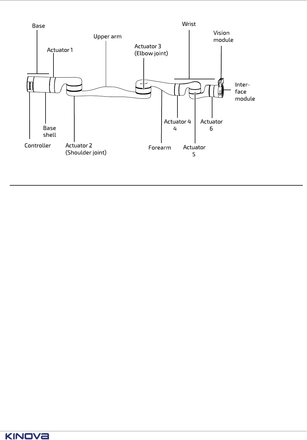
The robot consists of:
• base
• actuators
• interface module
• vision module (option)
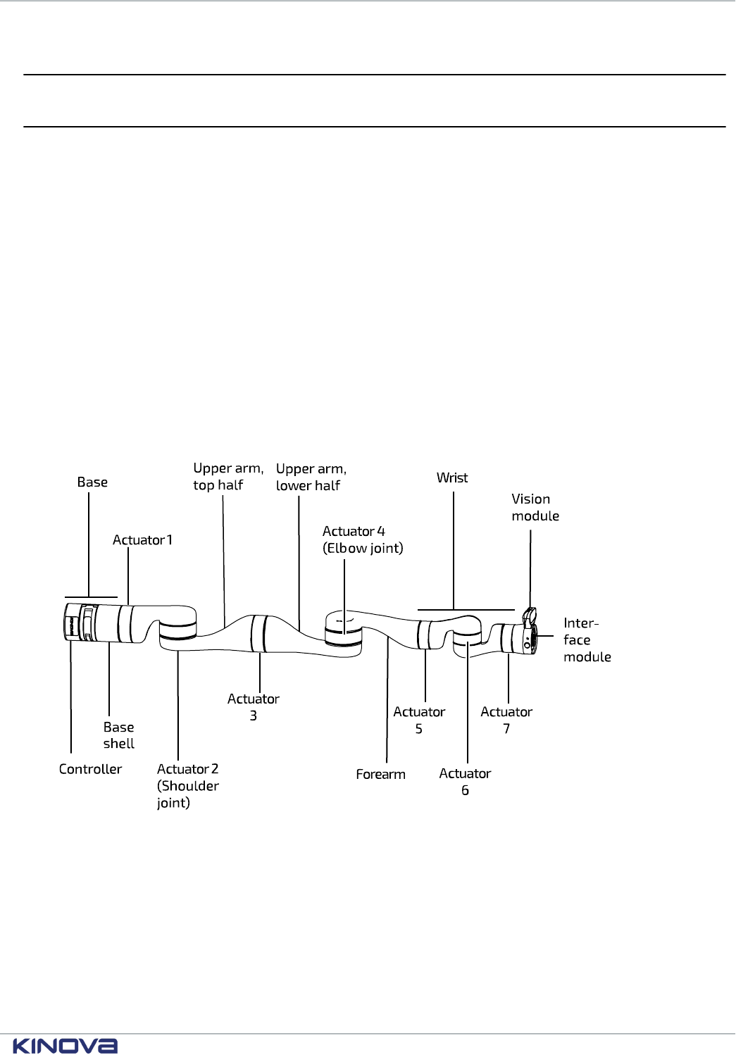
The following image shows the main components of the robot. The robot is available in two models:
• 7 degrees of freedom (DoF)
• 6 degrees of freedom (DoF)
This document describes both models. Wherever there is information specific to only one particular
model, this will be indicated in the text.
Each of these DoF models come in multiple different hardware configuration options. The details of
this will be discussed later in the document.
Figure 1: Robot main components (7 DoF model with quick connect base and vision module)
+1 514-277-3777 kinovarobotics.com
© 2022 Kinova inc. All rights reserved.
Kinova® Gen3 Ultra lightweight robot User Guide 14
Figure 2: Robot main components (6 DoF model with fixed base and vision module)
Base
The robot base provides for physical mounting of the robot and for power and communication/control. The
base is the brains of the robot and contains a number of important internal components. The base comes in
two different versions, quick connect and fixed base.
The robot base is the lower foundation of the robot and provides interfaces for:
• physical mounting of the robot
• power and communication/control
The base includes a connector panel at the rear for connecting to power and external devices and
mounting holes on the bottom surface for affixing the robot at the mounting site.
The base includes a built-in controller that serves as the brain of the robot. The internal
components of the base controller include:
• CPU
• Wi-Fi / Bluetooth adapter (Only Wi-Fi is used at present)
• Ethernet switch
• USB hub
• temperature sensor
• accelerometer/gyroscope
A Linux web server runs on the base and manages connectivity between the base and the robot
devices, and between the robot and an external computer.
The robot base comes in two versions:
• quick connect base (7 DoF legacy model only)
• fixed base (6 DoF and 7 DoF)
The table below summarizes the different base options.
+1 514-277-3777 kinovarobotics.com
© 2022 Kinova inc. All rights reserved.
Kinova® Gen3 Ultra lightweight robot User Guide 15
Table 6: Base options
Degrees of freedom model Base options
6 DoF Fixed base
Fixed base
7 DoF
Quick connect base (legacy only)
Quick connect base
The quick connect base is a two-part structure. This allows the robot controller to be mounted in one place
while allowing the robot to be quickly attached and detached. This base option is only available for the 7 DoF
robot model.
With the quick connect base, the base is a two-part structure securing the robot onto its physical
mounting point and connecting the robot to power and control signals. This consists of two parts:
• quick connect controller
• base shell
The two-part system enables simple connection and disconnection of the base shell and quick
connect controller. This allows the robot to be quickly detached from its mounting site and
controller without disconnecting any cables. This can be useful for transport, for removal of the
robot for servicing, or for convenient re-siting of robots between multiple installation sites.
The quick connect controller contains the robot controller and includes the base mounting
interface and rear connector panel. The quick connect controller can be mounted in place at the
mounting site with power and control cables connected.
The base shell is the bottom part of the robot shell connected to the first actuator. It slides onto the
quick connect controller.
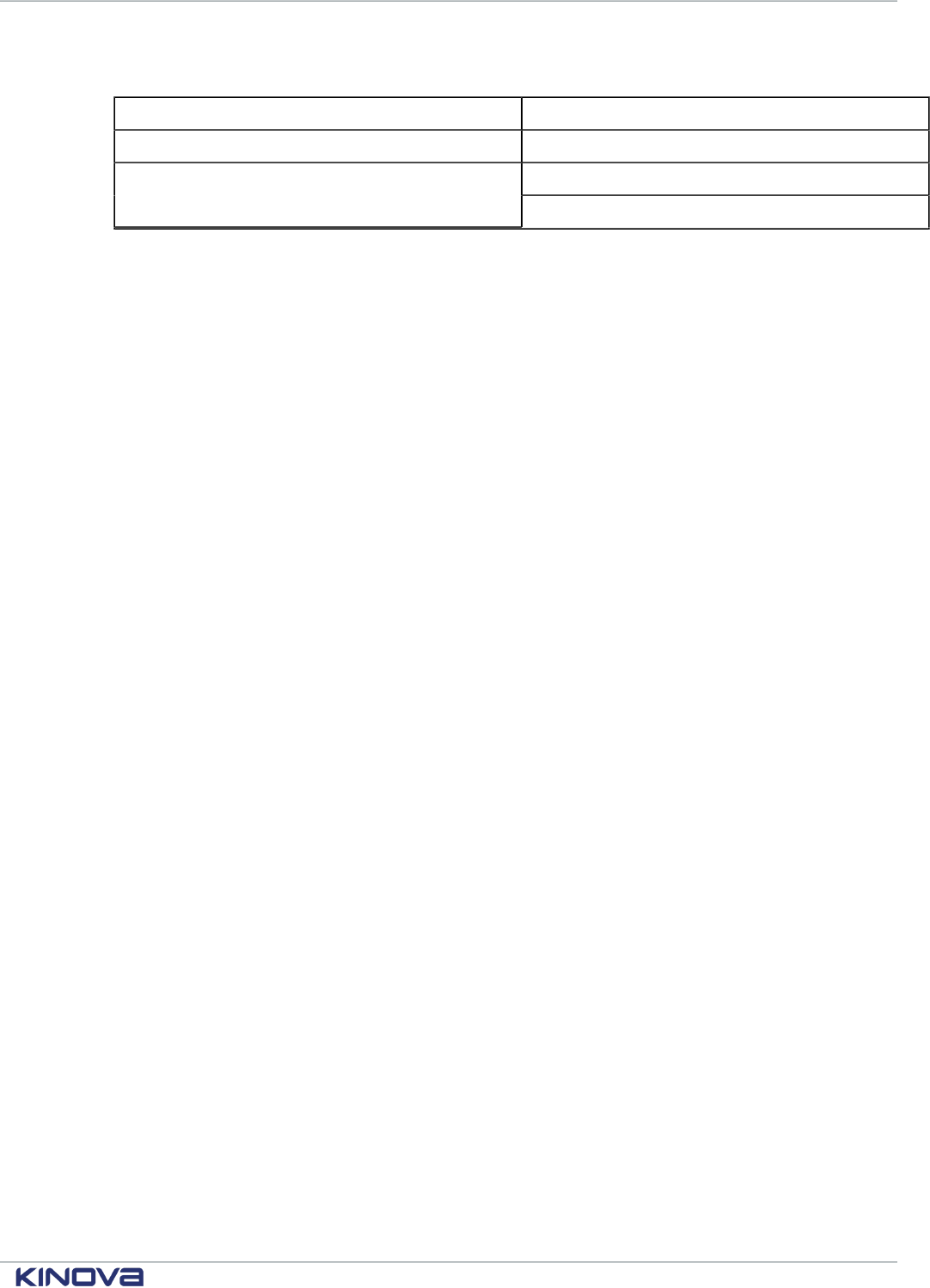
A mating interface on the top of the quick connect controller provides an electrical connection
between the quick connect controller and the rest of the robot.
+1 514-277-3777 kinovarobotics.com
© 2022 Kinova inc. All rights reserved.
Kinova® Gen3 Ultra lightweight robot User Guide 16
Figure 3: Quick connect controller
Note: Be careful to avoid damage to the electrical contacts on the mating interface of the
controller when the base shell is disconnected. Make sure to keep the surface dry and free
from dust. Wipe down with a soft dry cloth to keep the interface clean.
The base shell is secured in place on the controller by closing the clamp.
Figure 4: Connecting quick connect base
The clamping mechanism and mating interface allow the robot to be quickly and easily removed
from the controller while leaving the controller still mounted in place with cables connected.
Note: Currently the quick connect base option is only available for the 7 DoF robot model.
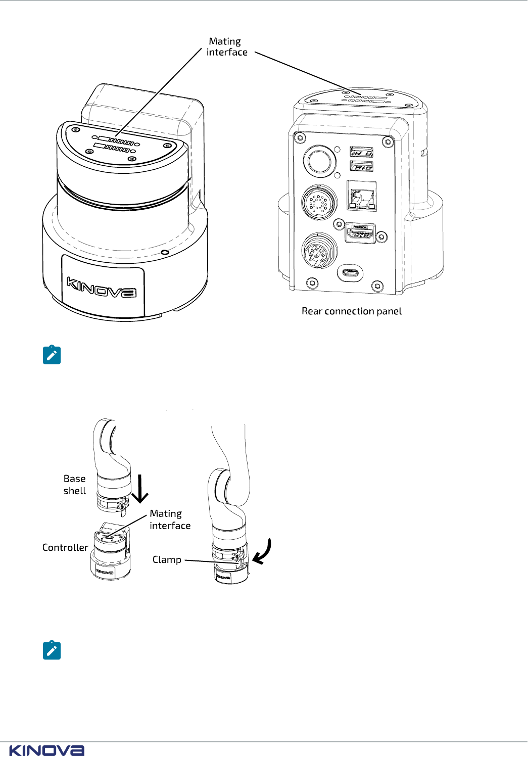
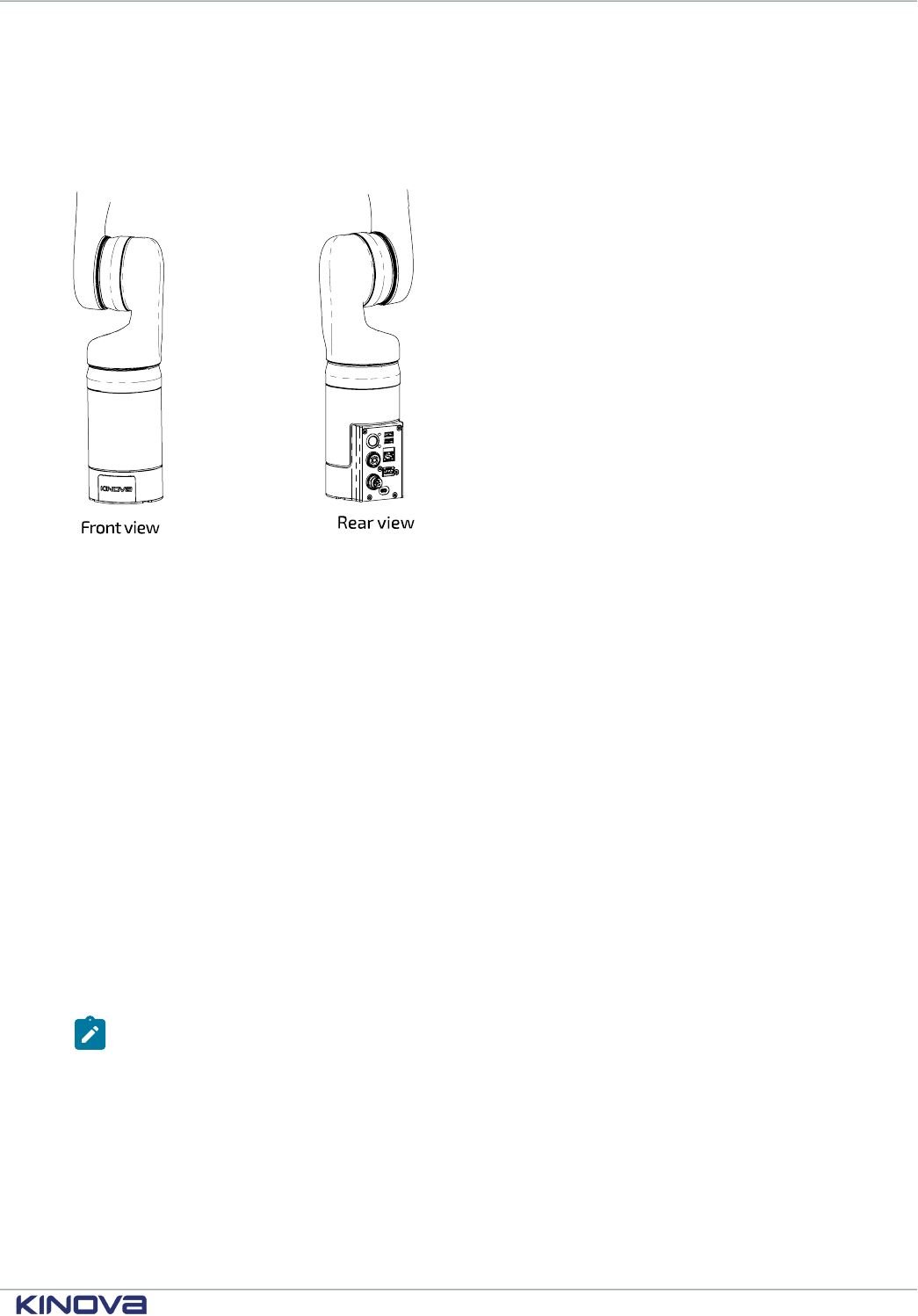
Fixed base
The fixed base is a one piece base with the controller integrated with the robot. This base option is available
for both the 6 DoF and 7 DoF robot models.
+1 514-277-3777 kinovarobotics.com
© 2022 Kinova inc. All rights reserved.
Kinova® Gen3 Ultra lightweight robot User Guide 17
The fixed base is a one piece base integrated with the robot. The fixed base includes the same
controller internals and the same rear connector panel and mounting interface as the standard
quick connect base controller. This rigid, one part base allows for an added measure of stability and
precision compared to the quick connect base, but with less flexibility and convenience when it
comes to mounting and dismounting the robot.
Figure 5: Fixed base
Base connector panel
The base connector panel is located on the back of the controller part of the robot base. This provides a
connection point for the power supply and various cables. It also contains the power on/off switch and an LED
indicator.
The connector panel is located at the rear of the base. The connector panel is the same for all Gen3
robot models It features the following elements:
• On/Off power switch
• blue power LED indicator
• red/amber/green status LED indicator
• HDMI Out (Internal use only)
• Micro USB (For firmware updates; internal use only)
• USB 2.0, type A - qty 2 - for wired controller. Top port 1 A for charging. Bottom port 500 mA max,
for peripherals.
• RJ-45 Gigabit Ethernet (LAN)
• Binder-USA 09 0463 90 19 (Internal use only)
• Lumberg 0317 08 (power)
Note: Cables connected to the base controller must be less than 3 m in length. If not, you
must perform a risk analysis. Cables longer than 3 m can potentially have an effect on radio
frequency emissions and the immunity of the product.
+1 514-277-3777 kinovarobotics.com
© 2022 Kinova inc. All rights reserved.
Kinova® Gen3 Ultra lightweight robot User Guide 18
(Internal use on ly)
Figure 6: Base connector panel
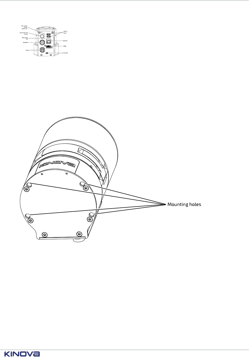
Base mounting interface
The bottom of the base has a mounting interface for attaching the robot to a mounting plate or directly to a
surface.
The base has a mounting interface with four mounting holes (M6) on its underside allowing for a
few different mounting options.
Figure 7: Base mounting interface
For the standard quick connect base option, the quick connect controller is shipped detached from
the base shell and connected with screws to a circular mounting plate. This mounting plate has
multiple sets of through holes to allow for:
• attaching the mounting plate to the base mounting holes
• attaching the mounting plate to a surface
The mounting plate also includes a slot to insert a table clamp between the robot and the mounting
plate. The table mounting plate + table clamp mounting option allows for quick setup and takedown
tabletop mounting.
+1 514-277-3777 kinovarobotics.com
© 2022 Kinova inc. All rights reserved.
Kinova® Gen3 Ultra lightweight robot User Guide 19
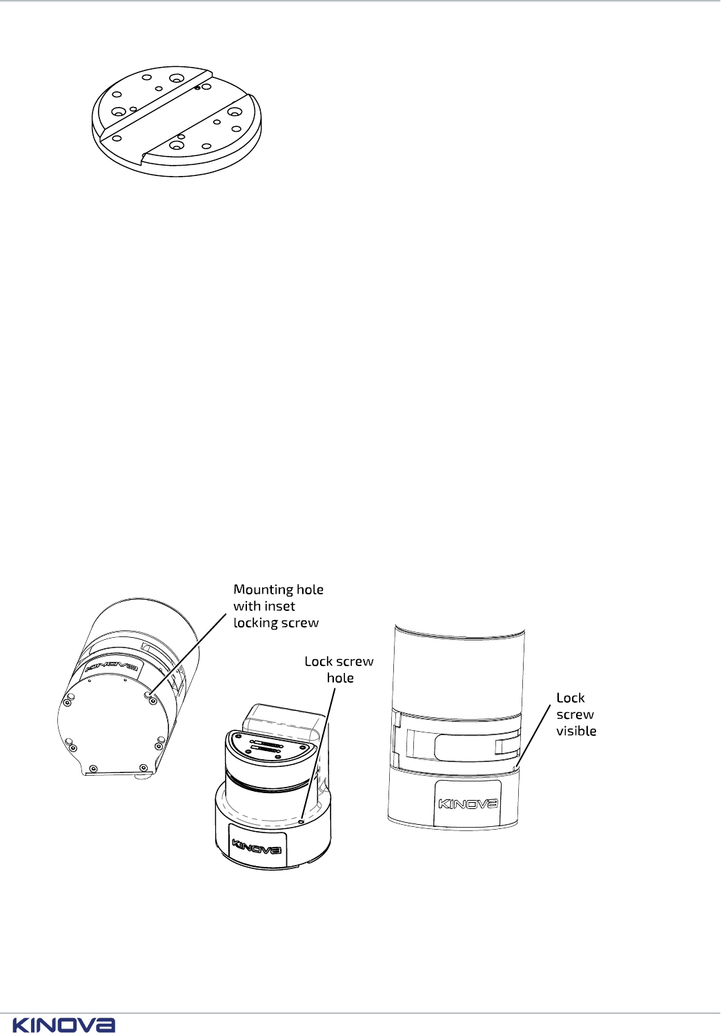
Figure 8: Mounting plate
When attached, the mounting plate can be removed from the base by removing the screws, giving
access to the four mounting holes and allowing the controller to be mounted directly on the
surface.
For the fixed base option, the mounting plate is detached from the base when shipped and needs to
be attached before mounting the robot using the mounting plate.
Quick connect base feature - locking screw
The quick connect base features an inset locking screw within the mounting hole on the front
bottom left (from the perspective of an observer behind the connector panel). Turning the locking
screw with a 3 mm hex key clockwise will cause the screw to go forward and protrude up to a few
millimeters through a hole above the top surface of the controller until it reaches the end of its
travel.
If the base shell is already clamped onto the controller when this is done, the set screw will
interface with a mechanism on the clamp, preventing the clamp from opening until the set screw is
withdrawn. This serves as a safety mechanism. There is a hole on the front face of the clamp where
the end of the lock screw can be seen when it is fully engaged. Confirm visually that the lock screw
is not engaged before trying to open the clamp.
Figure 9: Locking screw mechanism
More details about the base mounting interface and its features can be found in the mounting
instructions in the Getting started section of this user guide.
+1 514-277-3777 kinovarobotics.com
© 2022 Kinova inc. All rights reserved.

Kinova® Gen3 Ultra lightweight robot User Guide 20
Actuators
The robot contains actuators which power the rotational movement at the robot joints. The robot contains
both large and small actuators with distinct performance capabilities. The actuators contain sensors.
The rotational motion at each of the joints of the robot is powered by rotary actuators. There
is one actuator for each joint. Each actuator allows for potentially unlimited rotation in either
direction. There are software limits, however, on some joints to avoid collisions between robot shell
segments.
There are two sizes of actuator:
• small
• large
Each actuator has:
• torque sensing
• current and temperature sensing on each motor phase
Wrist joints use small actuators, while large actuators are used for other joints. All actuators are
equipped with a 100:1 strain wave gear for smooth motion.
The actuators are connected to each other and to the interconnect board using a series of 41-pin
flex cables. These cables convey:
• power
• 2 x full-duplex 100 Mbps Ethernet
º one for 1 kHz control
º one for vision / expansion data traffic
Actuator Specifications:
• actuator speed (maximum, unloaded):
º 25 RPM (small)
º 13 RPM (large)
• actuator torque (small):
º 13 N·m (nominal)
º 34 N·m (peak)
• actuator torque (large):
º 32 N·m (nominal) for robots built before 2022-09, 39 N·m (nominal) for robots built after
2022-09
º 54 N·m (peak)
Interface module
The interface module is located on the wrist of the robot and provides an interface for connecting a gripper or
other tool. The interface module contains both mechanical and electrical interfaces.
The interface module provides an interface for connecting a gripper or other tools at the end of the
arm. The interface module also provides a mounting point and connection for the vision module.
The interface module has a connection interface at the end of the arm, and is surrounded on the
sides by a bracelet shell. The vision module (when present) is mounted on the top of the bracelet.
+1 514-277-3777 kinovarobotics.com
© 2022 Kinova inc. All rights reserved.
Kinova® Gen3 Ultra lightweight robot User Guide 21
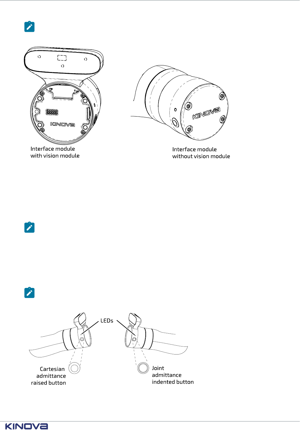
Note: While the vision module is standard on the interface module, there is an option to
purchase the robot without it. The interface module for this option otherwise has the same
components and connectivity as the standard interface module.
Figure 10: Interface module options
The bracelet includes two buttons used to activate admittance modes to interact with the robot.
By default the button on the right hand side (viewed from behind) puts the arm into Cartesian
admittance while the button on the left puts the arm into Joint admittance. The two buttons can
be distinguished easily by touch without looking; the Cartesian admittance mode button sticks out
from the surface in the center, while the joint admittance mode button is slightly indented in the
center and ring-shaped.
Note: Pressing the two buttons together will put the 7 DoF model into null space admittance
(but has no effect for the 6 DoF model).
The buttons are also used, in conjunction with the Kinova
®
Kortex™ Web App, in support of teaching
mode. There, the buttons are used to capture positioning snapshots for simplified creation of
motion sequences. For more information about teaching mode, see the Web App User Guide section
of this document.
The bracelet also includes two amber LEDs.
Note: For the no vision module model of the robot, the bracelet LEDs serve as useful visual
reference cue for the orientation of the wrist. In the reference frame of the interface module,
the LEDs will be "above" (positive y direction) their respective wrist buttons.
Figure 11: Bracelet features
The interface module takes a 41-pin input from the last actuator of the robot.
+1 514-277-3777 kinovarobotics.com
© 2022 Kinova inc. All rights reserved.
Kinova® Gen3 Ultra lightweight robot User Guide 22
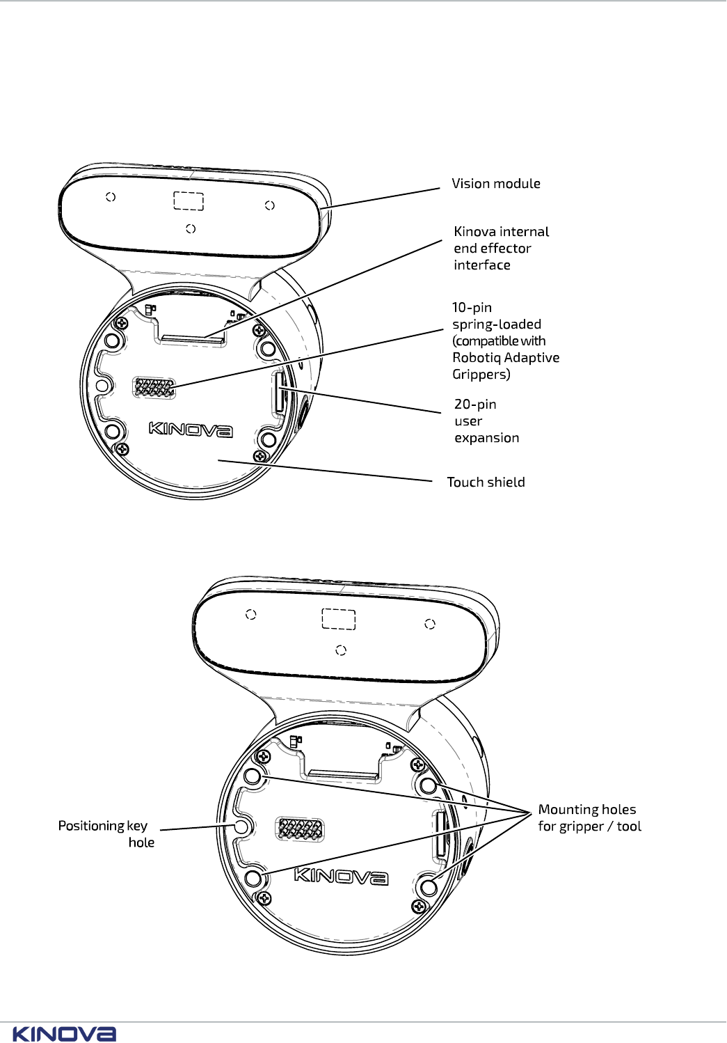
The interface exposes connectors that allow different end effectors to be integrated with the robot.
It features:
• Kinova internal end-effector interface
• 10-pin spring-loaded connector with RS-485 (compatible with Robotiq Adaptive Grippers)
• 20-pin user expansion interface
Figure 12: Interface module
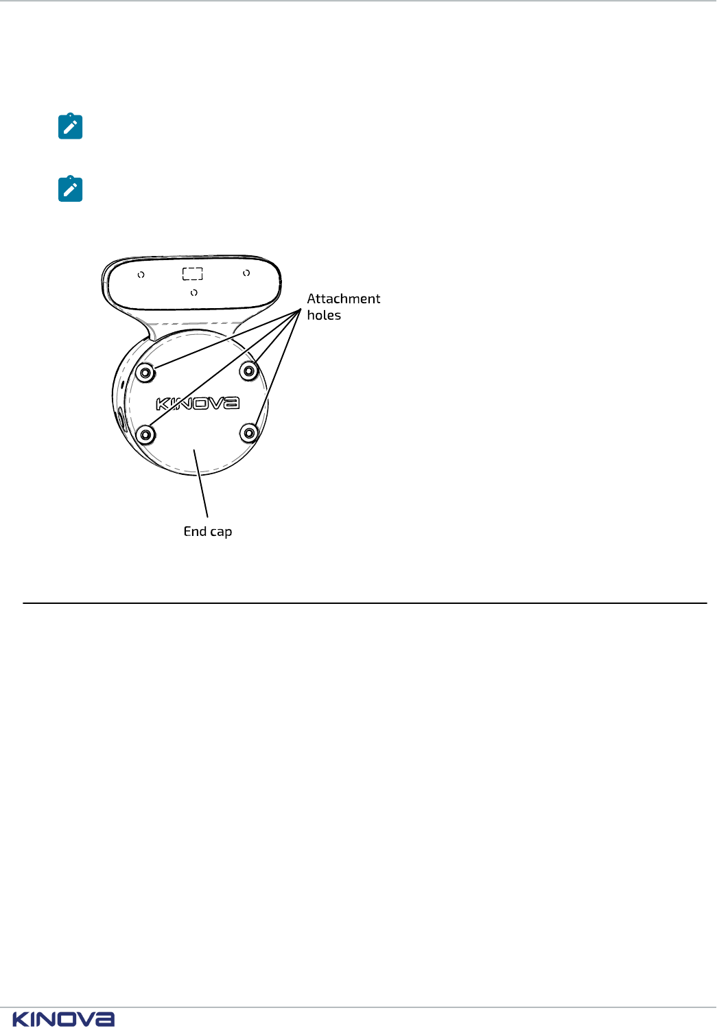
The interface also includes four mounting holes for physical mounting of an end effector and a
position key hole used for alignment of the end effector in the right orientation.
Figure 13: Mounting holes and positioning key hole
+1 514-277-3777 kinovarobotics.com
© 2022 Kinova inc. All rights reserved.
Kinova® Gen3 Ultra lightweight robot User Guide 23
The interface module includes a 6-axis accelerometer / gyroscope. The module also includes an
Ethernet switch to route connectivity and control data between the interface module and the
vision module (if present) and any connected tool (e.g. gripper).
Note: The printed circuit board (PCB) of the interface module is partially covered with
a touch shield with holes to expose only the output connectors - 10-pin spring loaded
connector, 20-pin user expansion connector, and Kinova internal end effector interface.
Note: When there is no end effector present, it is recommended to place an end cap over
the face of the interface module. Kinova provides an end cap with the robot. This end cap is
attached to the interface with screws using the mounting holes on the interface. The end cap
needs to be removed to attach an end effector to the robot.
Figure 14: End cap
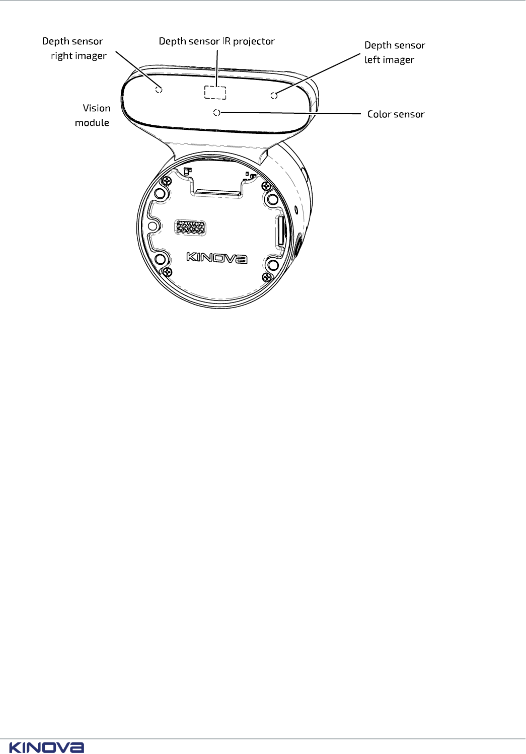
Vision module
The vision module enables computer vision applications with the robot. The vision module contains a depth
sensor with two stereo imagers and an RGB color sensor.
The vision module is a module provided by Kinova to enable robotic computer vision applications.
For robots including the vision module, the vision module is mounted on the top side of the
interface module. A housing containing sensors protrudes from the top of the interface module.
The sensors are contained on the front face of the housing, facing out parallel to the axis of the last
actuator.
The vision module is used to capture and stream image data captured looking in the direction
the end of the robot (or attached tool) is pointed. The Vision module includes both a color sensor
(Omnivision OV5640) and a stereo depth sensor (Intel® RealSense™ Depth Module D410).
+1 514-277-3777 kinovarobotics.com
© 2022 Kinova inc. All rights reserved.
Kinova® Gen3 Ultra lightweight robot User Guide 24
Figure 15: Vision module sensors
The color sensor captures a 2D array of RGB pixel data representating the field of view from the
perspective of the sensor.
The depth sensor includes an IR projector and two stereo imagers - left and right. Here left and
right are from the perspective of an observer looking out from the sensor toward the imaged
region. The depth sensor captures a 2D array of pixels and the depth for each pixel within the field
of view of the sensor.
Together, the two sensors allow the capture of RGBD (color and depth) data. Both camera sensors
can be configured using the Kinova
®
Kortex™ VisionConfig interface.
Note that performance for the Vision module depth sensor may be degraded at temperatures
below 0° C. For more details, please consult the depth sensor data sheet.
The color and depth sensors data streams are made accessible to developers through a
computer with a connection to the robot. For more information on accessing these data streams
programatically, see here.
Vision module specifications
Color sensor:
• resolution, frame rates (fps), and fields of view (FOV):
º 1920 x 1080 (16:9) @ 30, 15 fps; FOV 47 ± 3° (diagonal)
º 1280 x 720 (16:9) @ 30, 15 fps; FOV 60 ± 3° (diagonal)
º 640 x 480 (4:3) @ 30, 15 fps; FOV 65 ± 3° (diagonal)
º 320 x 240 (4:3)@ 30, 15 fps; FOV 65 ± 3° (diagonal)
• focusing range - 30 cm to ∞
Depth sensor:
+1 514-277-3777 kinovarobotics.com
© 2022 Kinova inc. All rights reserved.
Kinova® Gen3 Ultra lightweight robot User Guide 25
• resolution, framerates (fps), and fields of view (FOV):
º 480 x 270 (16:9) @ 30, 15, 6 fps; FOV 72 ± 3° (diagonal)
º 424 x 240 (16:9) @ 30, 15, 6 fps; FOV 72 ± 3° (diagonal)
• minimum depth distance (min-Z) - 18 cm
Robot communications and network interfaces
The robot is made up of a number of devices. These devices contain Ethernet switches and are connected
together in a network. There are three VLANS present for control, expansion/vision, and external
connections.
The devices in the robot, from the base of the arm through the chain of actuators, to the interface
module at the end of the arm, are daisy chained together using 41-pin flex cables which carry power
and communications.
The base, actuators, and interface module each contain an Ethernet switch. The Ethernet port on
the connector panel of the base controller allows an external computer to connect to the Ethernet
switch of the base.
The Kinova vision module and any 3rd party tool that makes use of Ethernet communications
user expansion pins in the interface connect directly to the interface module Ethernet switch.
Other tools (for example any gripper interfacing using the 10-pin spring loaded connector on the
interface) will interface instead with the interface module CPU (which is connected to the Ethernet
switch).
Together, this enables dual Ethernet networks between all the devices (base, actuators, interface,
Vision module, and end effector tools) with data carried between the base and interface over the
41-pin flex cables. This is accessible from a client computer via the 1 Gbps Ethernet port on the
base controller connector panel.
The flex cables carry two distinct 100 Mbps Ethernet communications channels.
• one is for control and monitoring of actuators, interface module, and gripper (if present)
• the other is for data transmission for the vision module and expansion.
Each device connected to one of the Ethernet switches has an IP address to allow routing of
communications, transmitted using UDP.
The actuators and interface module have the following default IP addresses:
Table 7: Actuator and gripper IP addresses
Device IP address
Actuator 1 10.10.0.10
Actuator 2 10.10.0.11
Actuator 3 10.10.0.12
Actuator 4 10.10.0.13
Actuator 5 10.10.0.14
Actuator 6 10.10.0.15
Actuator 7 (for 7 DoF model) 10.10.0.16
Interface module 10.10.0.17
+1 514-277-3777 kinovarobotics.com
© 2022 Kinova inc. All rights reserved.
Kinova® Gen3 Ultra lightweight robot User Guide 26
The expansion devices (Vision module and expansion tool peripherals) have the following IP
addresses:
Table 8: Expansion IP addresses
Expansion Devices IP address
Vision module 10.20.0.100
Expansion device 10.20.0.200/24*
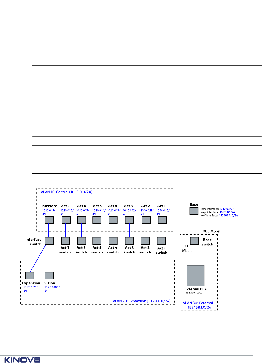
The robot Ethernet network features three VLANs:
• VLAN 10 : control
• VLAN 20 : expansion
• VLAN 30 : external
The base has network interfaces to all three of these VLANs:
Table 9: Base network interface IP addresses
VLAN IP address
CTRL interface IP address 10.10.0.1/24*
EXP interface IP address 10.20.0.1/24*
EXT interface IP address 192.168.1.10/24*
The graphic below illustrates the topology of the networks.
Figure 16: Networks diagram (7 DoF model shown)
* CIDR notation
+1 514-277-3777 kinovarobotics.com
© 2022 Kinova inc. All rights reserved.

Kinova® Gen3 Ultra lightweight robot User Guide 27
Getting started
Overview
Overview of the getting started contents.
The pages that follow lead you through getting started with the robot. This includes:
• unboxing
• physically mounting the robot securely
• provisioning electrical power
• controlling the robot using an Xbox gamepad
• moving the robot in admittance using physical buttons
• connecting a computer to the robot
•
connecting to the Kinova
®
Kortex™ Web App
What's in the case?
Description of robot shipping case contents.
+1 514-277-3777 kinovarobotics.com
© 2022 Kinova inc. All rights reserved.
Kinova® Gen3 Ultra lightweight robot User Guide 28
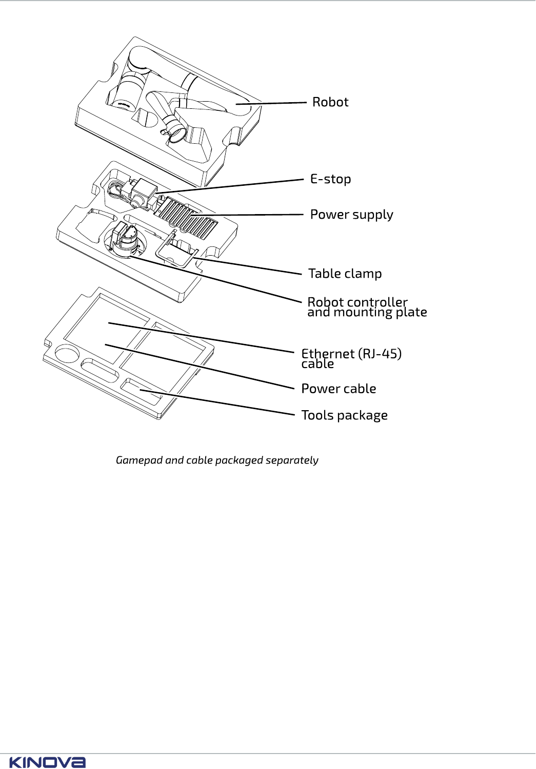
Figure 17: Gen3 Ultra lightweight robot shipping case contents (quick connect base option shown)
The shipping case contains the following contents.
At the top of the interior of the box, you will find the Quick Start Guide. The Quick Start Guide is a
large printed visual guide.
The Quick Start guide provides a handy reference for first steps, and should have you up and
running within 30 minutes. Make sure to keep the Quick Start Guide as a reference for people in
your team or organization getting newly acquainted with your robot. The Quick Start Guide is also
available on the Kinova website.
The contents of the box are arranged in three layers from top to bottom. These packing layers can
be removed from the box to unpack the contents.
In the top layer:
• Robot
In the second layer:
• Power adapter and cable with integrated emergency stop (E-stop) button
• Table clamp
+1 514-277-3777 kinovarobotics.com
© 2022 Kinova inc. All rights reserved.
Kinova® Gen3 Ultra lightweight robot User Guide 29
• Mounting plate alone (fixed base option)
• Mounting plate with robot controller attached (quick connect base option)
The bottom area contains:
• Ethernet (RJ-45) cable
• Power cable
• Bag with useful tools and fasteners
º hex keys: 3, 4 and 5 mm
º M5 x 40 mm screws (qty. 4)
An Xbox gamepad and cable are shipped with the robot, but packaged separately.
There is also space for storage of papers and other items.
Note: The shipping case is also useful for transportation and storage of the robot. Make sure
to save it and the packing layers within for future use.
Manipulating the robot joints when the robot is powered o
The robot joints can be manipulated by hand when the robot is powered off. This is useful when setting up the
robot for the first time.
When the robot is powered on, the actuators will hold their position and prevent the joints from
moving in response to external forces and torques. When the power is on, the arm will not move
except when commanded. The arm joints are stiff and you will not be able to rotate the joints with
your hands.
When the robot is powered off, as it is when you first receive the robot, the joints can be moved by
hand slowly.
Note: The shoulder joint (joint 2) is more stiff than the others, but can still be moved.
This moveability of the joints when the robot is unpowered is useful when taking the robot out of
the box and setting it up to get started. This lets you arrange the joints of the robot into a stable,
balanced position prior to mounting and powering on the robot.
Robot mounting options
Overview of the physical mounting options for the robot.
The first step to getting started with the arm after unboxing is to physically mount the arm in a
stable manner so that the robot can be connected and used.
The most basic mounting option uses the mounting plate and a table clamp to quickly mount the
robot on a tabletop in a "right side up," vertical orientation on a flat horizontal surface. This allows
for a quick, temporary installation allowing setup, light operations, and troubleshooting.
For more permanent installations, the robot can be mounted to a surface using screws.
Note that it is also possible to mount the robot in different orientations, depending on the needs of
your particular application. The sections that follow will describe this in more detail.
Mounting the robot on a tabletop with mounting plate and table clamp
Describes the steps to mount the robot oriented vertically on the edge of a tabletop using a table clamp.
+1 514-277-3777 kinovarobotics.com
© 2022 Kinova inc. All rights reserved.
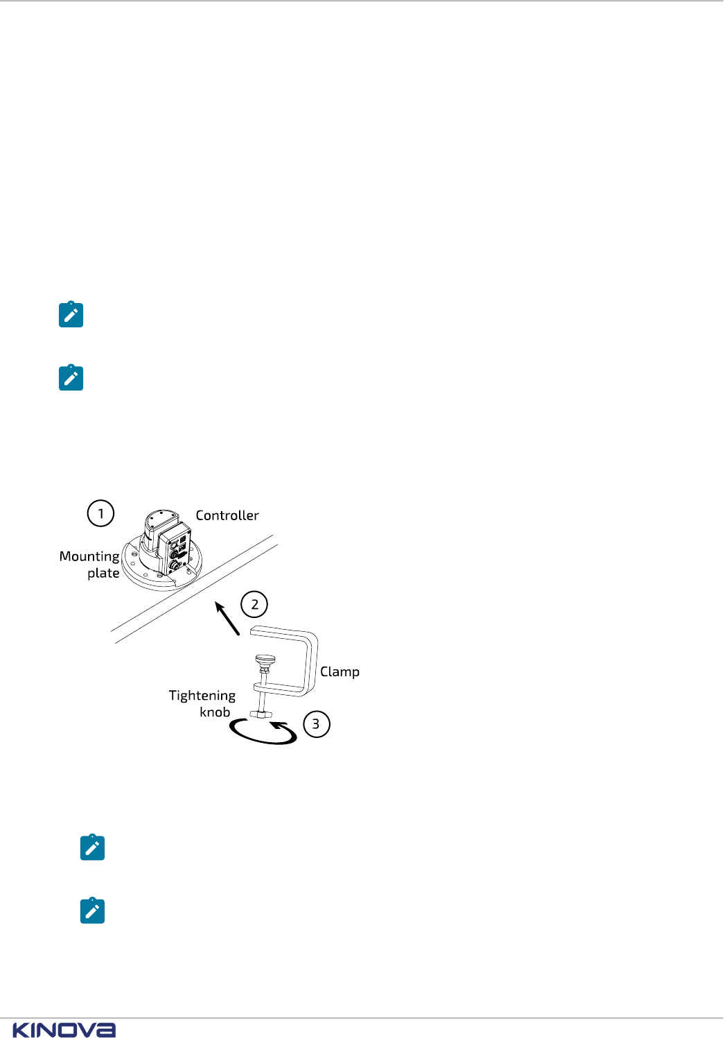
Kinova® Gen3 Ultra lightweight robot User Guide 30
Before you begin
The robot should have the joints of the robot unfolded so that it is in a stable, balanced position ready for
mounting. The mounting plate must be attached to the robot base.
• For the quick connect base option, the robot is shipped with the mounting plate already
connected to the base controller.
• For the fixed base option, the robot is shipped without the mounting plate attached and it will
need to be attached to the bottom of the base. See the base and mounting plate bolting patterns
later in this section for more details.
For a robot with a fixed base, you will need a second person to help with some of the steps.
About this task
The robot is mounted to a tabletop using the base mounting plate and a table clamp.
Note: The table must be large and sturdy to support a tabletop edge mounting. If the
table is too small or too flimsy, the weight of the robot at the table edge combined with the
movement vibrations may render it unstable.
Note: The table clamp is only intended for light operations (low payload, low speed, low
acceleration), quick demonstrations, and troubleshooting. Mounting using the table clamp
may affect repeatability and accuracy, since the base may move from its original location due
to force induced on the clamp from the back and forth manipulation of heavier payloads. For
permanent installations involving medium / heavy duty manipulation, the base must be fixed
securely to the mounting surface as described in Mounting the robot on a horizontal surface
without the table clamp on page 32.
Procedure
1. Place the mounting plate with robot base attached on the tabletop, next to the edge.
Note: You can place the robot base in one of two orientations. Either with the connector
panel facing out toward the edge of the table, or with the front side of the base controller
facing out.
Note: For the robot with fixed base, one person will need to hold the robot upright on the
table during this step and the next two steps while another person attaches the clamp.
2. Turn the tightening knob on the table clamp to open up the clamp and then slide the clamp into
the slot between the mounting plate and the bottom of the base controller.
+1 514-277-3777 kinovarobotics.com
© 2022 Kinova inc. All rights reserved.
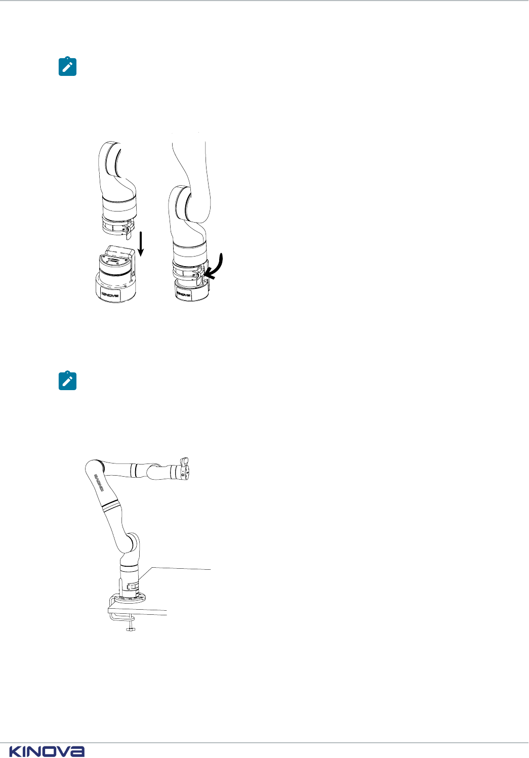
Kinova® Gen3 Ultra lightweight robot User Guide 31
3. Turn the tightening knob by hand until the mounting plant is firmly clamped to the table top.
Note: Do not overtorque.
4. (For robot with quick connect base) Make sure that the quick connect clamp at the bottom of
the robot base shell is opened. While holding the robot, you can now lower the base shell of the
robot onto and over the quick connect controller.
5. (For robot with quick connect base) Once the robot is fully lowered onto the quick connect
controller, close the quick connect clamp to secure the robot in place on the quick connect
controller.
Note: The quick connect clamp must be properly closed to ensure stability of the robot.
Damage can potentially be done to the robot if it is operated while unstable.
Results
The robot is now mounted on the tabletop.
What to do next
You can now proceed to connect the robot to the power supply and E-stop.
+1 514-277-3777 kinovarobotics.com
© 2022 Kinova inc. All rights reserved.

Kinova® Gen3 Ultra lightweight robot User Guide 32
Mounting the robot on a horizontal surface without the table clamp
Describes the steps to mount the robot on a horizontal surface without the table clamp, with or without the
mounting plate.
Before you begin
The robot should have the joints of the robot unfolded so that it is in a stable, balanced position ready for
mounting. If you want to use the mounting plate, the mounting plate will already need to be attached to the
robot base.
• For the quick connect base, the robot is shipped with the mounting plate already connected to
the base controller.
• For the fixed base, the robot is shipped without the mounting plate attached and it will need to
be attached to the bottom of the base. See the base and mounting plate bolting patterns later in
this section for more details.
For a robot with a fixed base, you will need a second person to help with the procedure.
About this task
Here, we describe mounting the robot in a vertical orientation on a flat, horizontal surface, affixing either the
mounting plate or the base to the surface using screws and sunk holes in the surface. This provides for a much
more stable and robust permanent mounting option compared to using the table clamp, and is the option to
use for precision and safety if you want to operate the robot at high speeds and with high payloads.
Procedure
1. Choose whether to mount the robot base directly onto the surface, or whether to use the
mounting plate.
2. Using either the mounting plate bolting pattern or the controller bolting pattern or as a guide,
drill holes into the surface. If the base is to be mounted directly to the surface, the holes will
have to be drilled all the way through the mounting surface.
3. Place the robot base (with mounting plate, if applicable) onto the table. Carefully line up the
holes drilled in the surface with the holes on the mounting plate or the underside of the robot
base, as applicable.
Note: For the robot with fixed base, one person will need to hold the robot upright on the
table during this step and the next step while another checks the positioning and fixes the
robot base in place.
4. Use appropriate screws to fix either the base or the mounting plate to the surface. If the base is
mounted directly, the screws will need to go through the mounting surface from the other side.
+1 514-277-3777 kinovarobotics.com
© 2022 Kinova inc. All rights reserved.
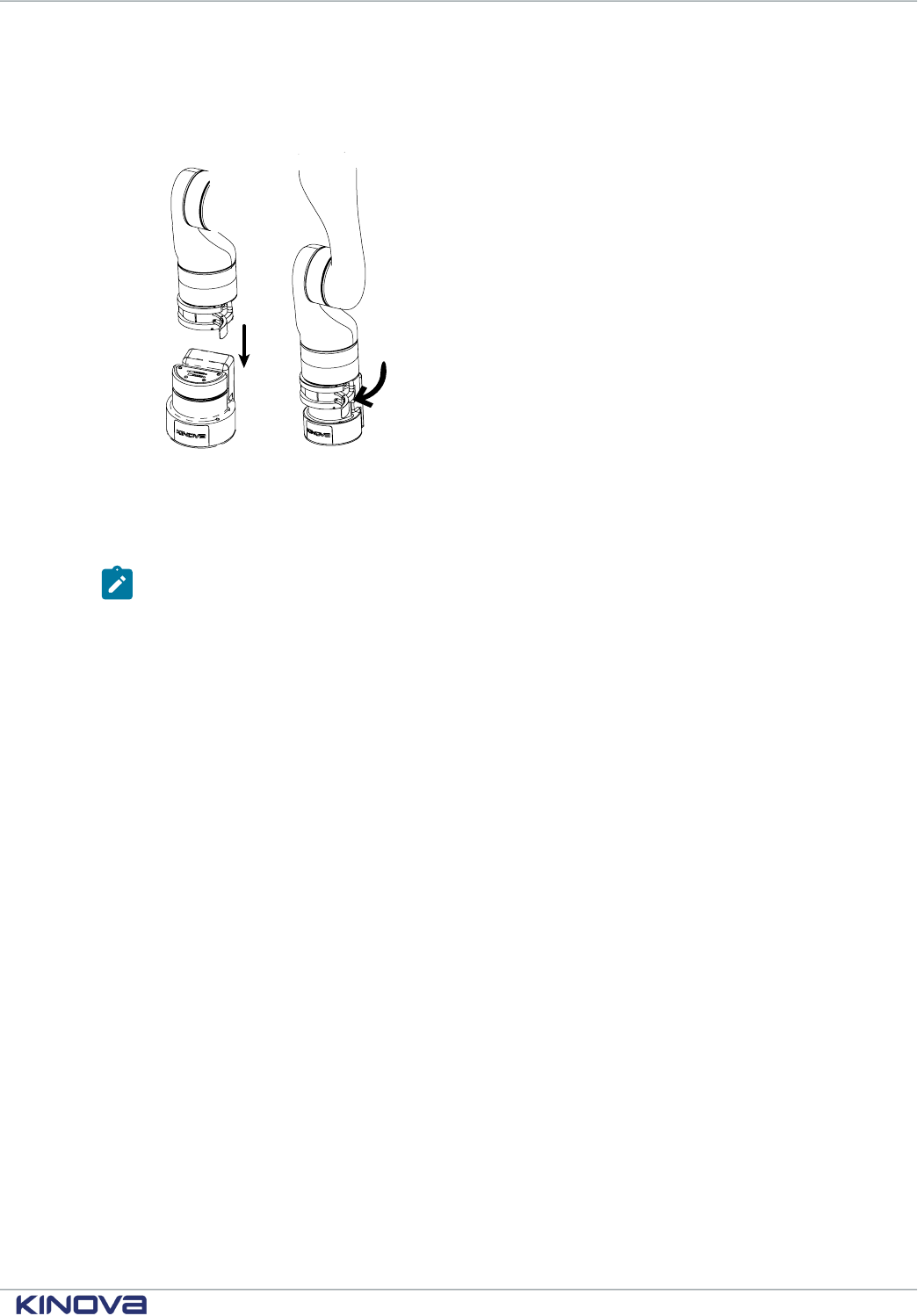
Kinova® Gen3 Ultra lightweight robot User Guide 33
5. (For robot with quick connect base) Make sure that the quick connect clamp at the bottom of
the robot base shell is opened. While holding the robot, you can now lower the base shell of the
robot onto and over the quick connect controller.
6. (For robot with quick connect base) Once the robot is fully lowered onto the quick connect
controller, close the quick connect clamp to secure the robot in place on the quick connect
controller.
Note: The quick connect clamp must be properly closed to ensure stability of the robot.
Damage can potentially be done to the robot if it is operated while unstable.
Mounting plate bolting pattern
Describes the bolting pattern of the mounting plate. This is useful when mounting the robot to a surface using
the mounting plate.
Overview
The mounting plate can be attached to the robot base using four M6 x 30 socket head cap screws
passing through the bottom of the mounting plate into corresponding holes in the bottom of the
base. The mounting plate has two sets of M8 screw holes (4 holes) and one set of counter-sunk M6
screw holes (4 holes) available for affixing the mounting plate to a surface.
+1 514-277-3777 kinovarobotics.com
© 2022 Kinova inc. All rights reserved.
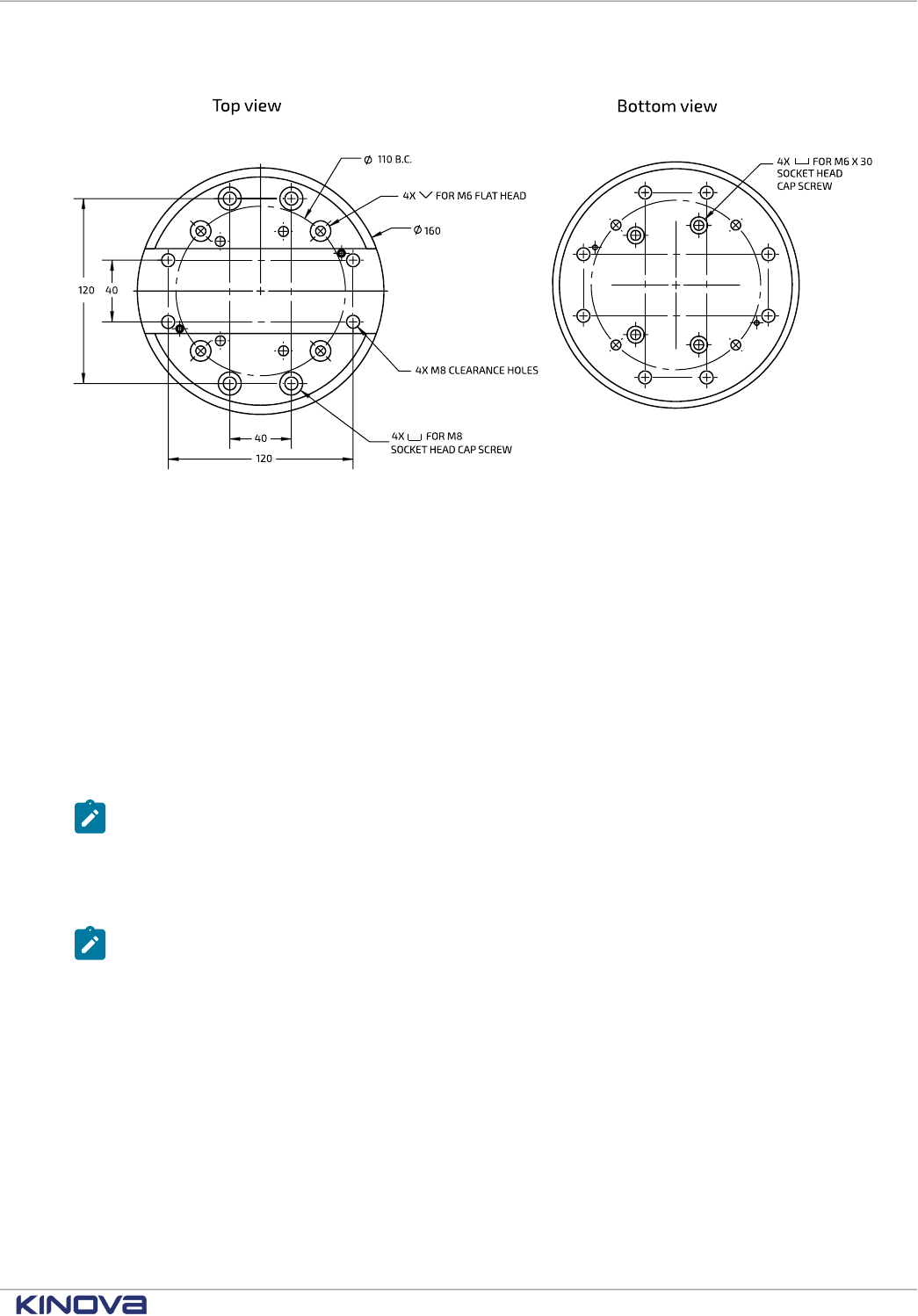
Kinova® Gen3 Ultra lightweight robot User Guide 34
Mounting details
Figure 18: Mounting plate bolting pattern
Base mounting interface bolting pattern
Describes the bolting pattern on the mounting interface on the underside of the base. This is useful when you
want to affix the robot base directly to a surface.
Overview
The underside of the base has a mounting interface with four M6 screw holes for mounting
purposes. These holes are used for attaching the mounting plate to the base. When the mounting
plate is removed, these holes can be used for mounting the base directly to a surface. In that case,
holes must be drilled through the surface so that screws can go through from the other side and
into the base mounting holes from underneath.
Mounting interface details
Note: The pattern of the mounting interface is the same for both quick connect and fixed
base options. However, for the quick connect base option, one of the screw holes in the
base (front left) features an inset locking screw. Turning the locking screw clockwise to the
end of its travel (using a 3 mm hex key) while the base shell is clamped to the quick connect
controller will lock the two together and prevent the clamp from being opened.
Note: Two of the mounting holes can optionally be used with shoulder screws. This allows
the robot to be mounted and dismounted with a more repeatable positioning.
+1 514-277-3777 kinovarobotics.com
© 2022 Kinova inc. All rights reserved.
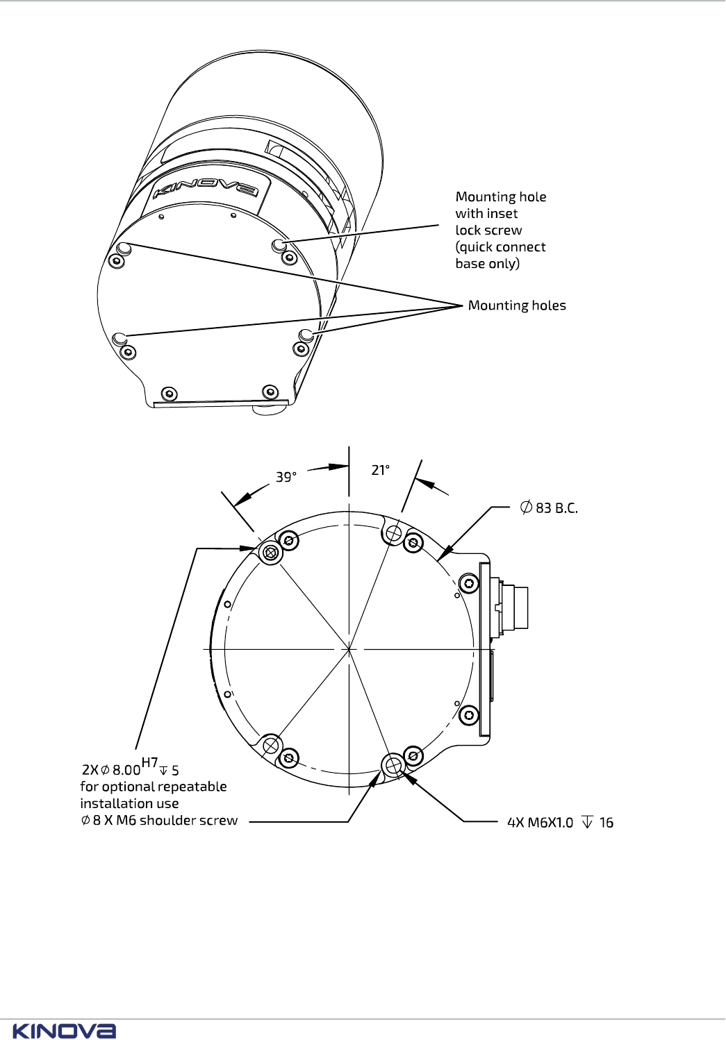
Kinova® Gen3 Ultra lightweight robot User Guide 35
Figure 19: Base mounting interface holes (quick connect base shown)
Figure 20: Base mounting interface holes pattern
Mounting the robot on a wall or ceiling
Describes how to mount the robot on a wall or ceiling.
The procedure for mounting is generally similar to that of mounting onto a horizontal surface:
+1 514-277-3777 kinovarobotics.com
© 2022 Kinova inc. All rights reserved.

Kinova® Gen3 Ultra lightweight robot User Guide 36
1. Choose whether to mount the controller directly to the surface, or using the mounting plate.
2. Drill holes in an appropriate pattern in the surface based on the appropriate bolting pattern
diagram.
3. Affix the controller or mounting plate to the surface with appropriate screws.
There are however important differences.
Follow all special considerations for wall and ceiling mounting. Perform a careful analysis of the
proposed mounting surface. Also, if your robot has a standard quick connect base, make sure to
mount and clamp the base shell onto the quick connect controller with the locking screw engaged
before mounting the robot on the surface. The details of this are described in the following sections.
Special considerations for wall and ceiling mounts
Describes special considerations that are important for wall and ceiling mounting of the robot.
For safety reasons, there are special preparations and steps that need to be undertaken before
mounting the robot on a wall or ceiling.
Before trying to mount the arm on a wall or ceiling, perform a comprehensive analysis of
weight, torque, and vibrations and ensure the material of the mounting surface structure is stable
enough.
If the robot uses a quick connect base, the locking screw on the bottom left front of the
controller must be screwed in fully with a hex key while the base shell is clamped on. This will
prevent the quick connect clamp from being opened while the arm is mounted on a wall or ceiling,
and provides an added measure of security. The robot therefore needs to be clamped to the base
controller and the lock screw must be adjusted before trying to mount the robot to the surface.
For wall mounting, the robot needs to be mounted with the controller connector panel facing
downwards. This is to prevent water ingress at the connector panel.
In a wall or ceiling mount, the gravity vector will have a different orientation than usual with
respect to the base reference frame. It will be necessary to set the gravity vector using the Web App
or API.
Note: A robot mounted in a ceiling mount is not certified for ingress protection.
Note: The Cartesian control of the robot is in relation to the base reference frame, which
will be rotated relative to the natural reference frame of the perspective of the user /
operator. You will need to apply the appropriate coordinate transformations to control the
robot in these orientations.
Adjusting the locking screw to secure the base clamp (quick connect base only)
Describes steps for adjusting the base locking screw of the quick connect base. The locking screw is used for
securing the clamp on the base. This increases safety in wall and ceiling mountings.
Before you begin
You will need a 3 mm hex key.
About this task
Adjusting the locking screw while the base shell is attached and clamped locks the clamp shut and prevents it
from being inadvertently opened. This improves the safety of the robot when mounted on a wall or ceiling.
+1 514-277-3777 kinovarobotics.com
© 2022 Kinova inc. All rights reserved.
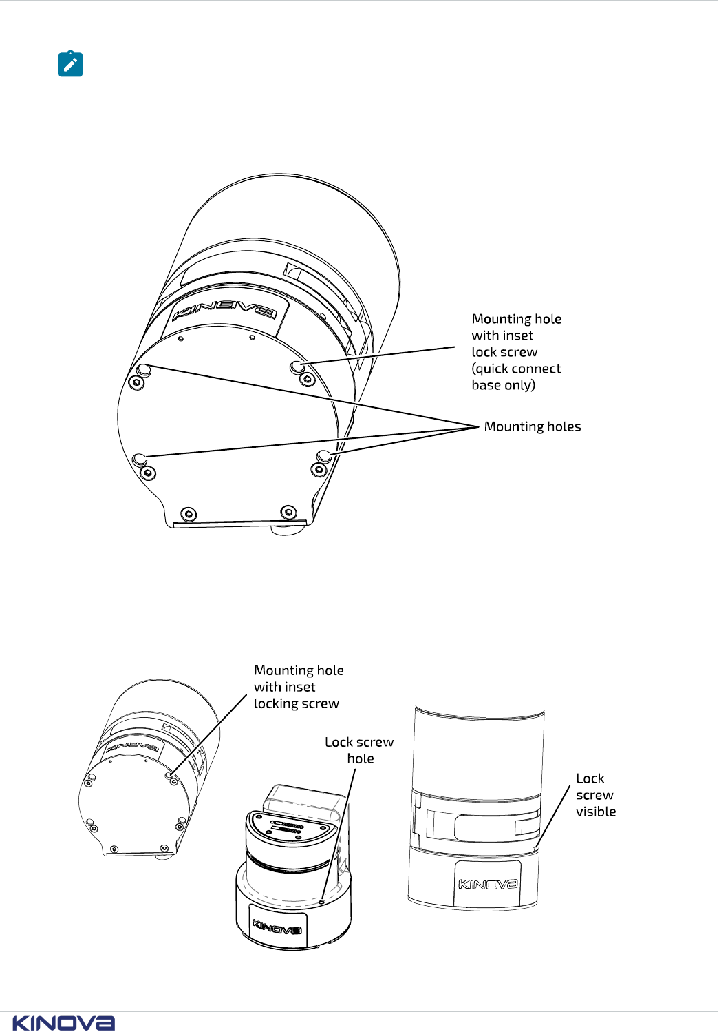
Kinova® Gen3 Ultra lightweight robot User Guide 37
Note: This procedure only applies in the case of the standard quick connect base.
Procedure
1. If the mounting plate is attached to the controller, one of the screws connecting the mounting
plate to the controller from below has to be removed to get at the locking screw. Identify the
mounting hole with the lock screw and remove it using the 3 mm hex key.
2. If the base shell and the robot are not already installed onto the quick connect controller, slide
the base shell onto the controller and close the clamp.
3. Using the same hex key, insert the end of the key into the mounting hole until the hex key
engages with the head of the lock screw. Turn the lock screw until it stops at the end of its travel.
There is a hole on the front of the clamp where the end of the lock screw can be seen when the
lock screw is engaged with the clamp mechanism. Confirm that you can see the screw.
4. Test the clamp to ensure that you can not open it.
+1 514-277-3777 kinovarobotics.com
© 2022 Kinova inc. All rights reserved.

Kinova® Gen3 Ultra lightweight robot User Guide 38
Robot power adapter and E-stop
The robot comes with a power adapter and cable to supply the robot with power from a wall outlet. The cable
includes an integrated E-stop.
The power adapter allows power to be supplied to the robot using a wall outlet as a source. The
cable from the power adapter connects to the power connector on the base controller using a
Lumberg 0322 08 connector.
The cable from the power adapter to the robot includes an integrated push-button E-stop
connected in series. The E-stop allows users to shut down the robot quickly in case of an
emergency.
To engage the E-stop, press down on the red button on top of the E-stop. This will cut the power to
the robot, causing it to shut it down.
When the power is cut, the robot will descend. There are mechanisms within the actuators
to slow the fall of the arm for safety purposes. However, it is recommended that if possible, users
cradle the robot as it falls.
To disengage the E-stop, rotate the button clockwise until it pops up.
Powering robot from a battery via a custom wiring harness
This section describes how to provide power to the robot from a battery using a custom wiring harness.
The most straightforward way to supply power to the robot is using the supplied power adapter and
cable to feed the robot from a nearby electrical outlet. This is the recommended solution for robot
power supply for the vast majority users.
In some applications, however, for example, for integration of the robot with a mobile platform, a
wall outlet will not be feasible as a source of power, and users will want to supply the robot with
power from a battery (24 V battery required).
The following information is intended for advanced users only.
Certification of the robot is under the assumption of power supply from a wall outlet using
the supplied power adapter. Use of a battery as power source may result in departure from these
standards. If you have a wall outlet available, use it as a power source.
Powering the robot using a battery power supply is done at the user's risk, and Kinova is not
responsible for any damage that might occur. We recommend that users contact Kinova technical
support for any questions related to powering the robot with a battery source.
For those who want to explore this option and understand the risks involved, Kinova provides (sold
separately) a power cable (p/n KR9764) to connect the robot to a battery. The details are as follows:
+1 514-277-3777 kinovarobotics.com
© 2022 Kinova inc. All rights reserved.
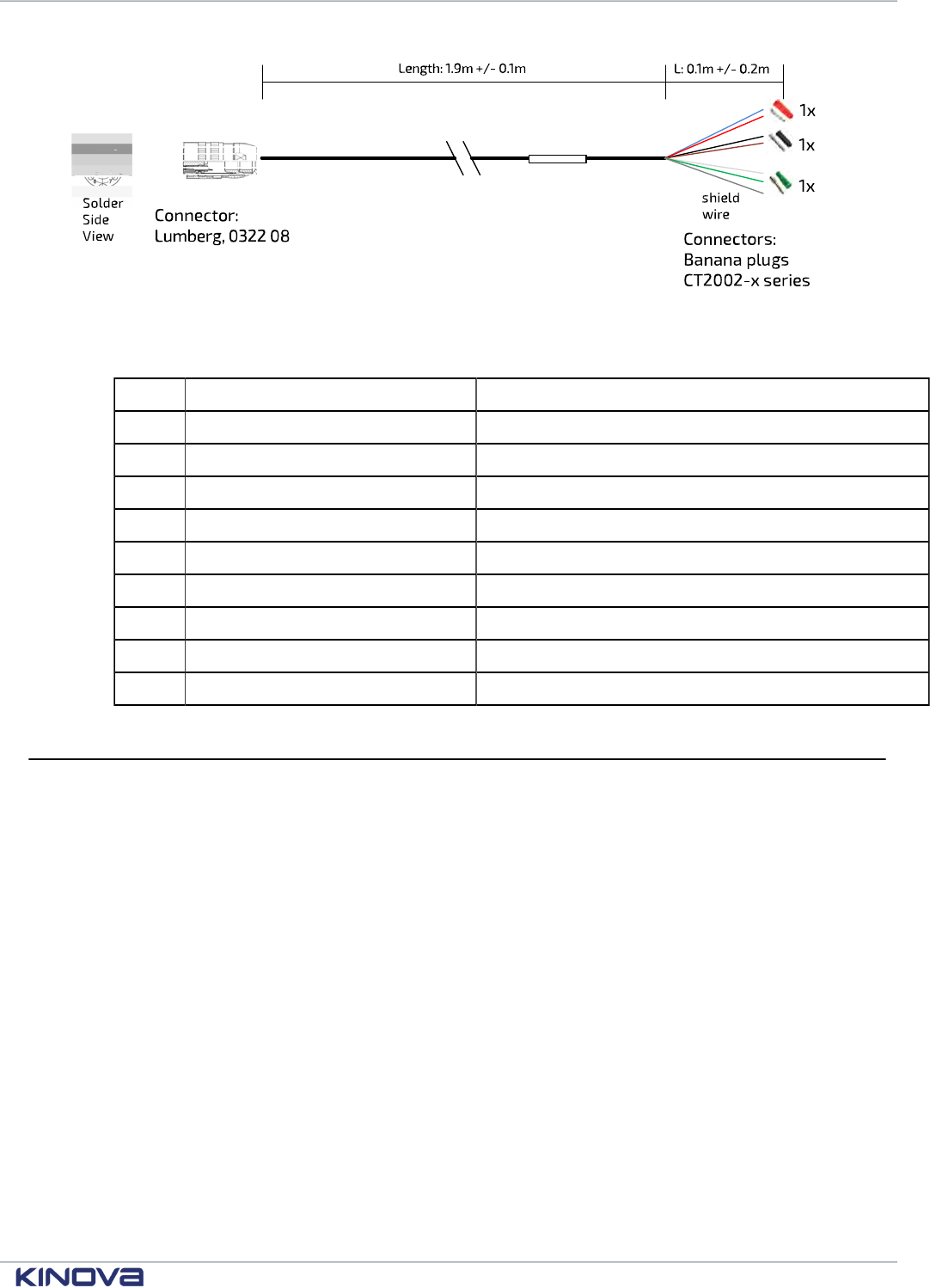
Kinova® Gen3 Ultra lightweight robot User Guide 39
Figure 21: KR9764 power cable
Table 10: KR9764 cable pinout
# Signal Wire color
1 24V_INPUT Red
2 24V_RETURN Black
3 CANL No connection
4 24V_RETURN Brown
5 CHASSIS Green
6 CHASSIS White
7 24V_INPUT Blue
8 CANH No connection
9 Connector backshell Shield wire
Powering on the robot
Describes steps to connect the robot to an electrical power source and power on the robot.
The robot is powered by a 24V power supply (P/N DTM300PW240D2).
To power up the robot:
1. Connect the captive cable from the power supply to the circular Lumberg connector on the rear
connector panel in the controller of the robot, rotating the outer cylindrical locking shell of the
connector until it is just tight enough to secure the connector.
2. Plug the power supply into a wall outlet.
+1 514-277-3777 kinovarobotics.com
© 2022 Kinova inc. All rights reserved.
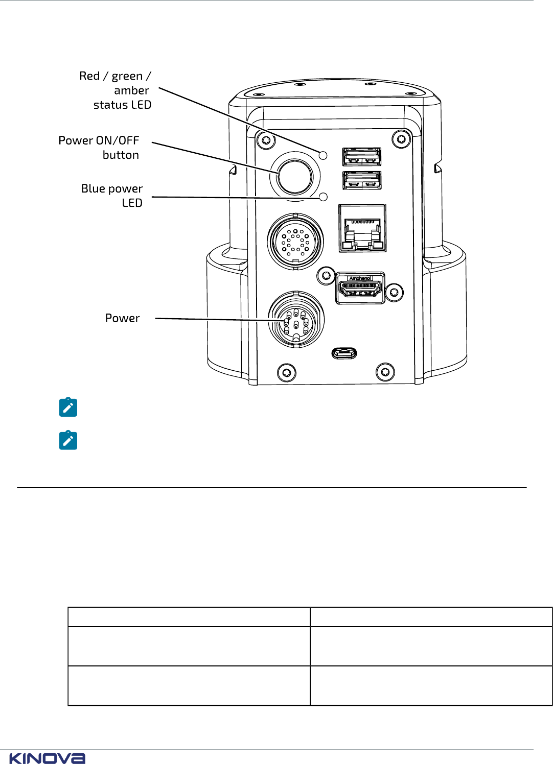
Kinova® Gen3 Ultra lightweight robot User Guide 40
3. Push the power button and hold in for 3 seconds to power up the robot. This will initiate the
power up sequence.
Note: When the robot is properly powered on, the blue power LED will be illuminated
green.
Note: Do NOT hold the power button down for too long. Holding the button for 10
seconds will result in a factory reset.
Power-up, booting, and initialization sequence
On pressing the power button of the robot, the robot goes through a boot up and initialization sequence. The
LED indications on the base give visual feedback during the power-up sequence.
When the power button is held in to initiate a power-up, the robot will go through a regular boot up
and initialization sequence.
The base LEDs will provide visual feedback as to the progress through the sequence, as follows:
Table 11: Power-up sequence LEDs indications
Sequence step LEDs indications
System booting
• Blue power LED, blinking
• Status LED, off
System initializing
• Blue power LED, solid
• Status LED, amber, solid
+1 514-277-3777 kinovarobotics.com
© 2022 Kinova inc. All rights reserved.
Kinova® Gen3 Ultra lightweight robot User Guide 41
Sequence step LEDs indications
System operating normally
• Blue power LED, off
• Status LED, green, solid
From start to finish, the process should take no more than 30 seconds, except during a firmware
update.
Resetting the robot to factory settings
The robot can be reset to factory settings using the following steps. This returns the robot to the state it was
in when first received.
About this task
At some point you may find it useful or necessary to roll back configurations on the robot to factory defaults.
This will return the robot to the state it was in when you received the robot.
Note: This procedure describes how to reset the robot to factory settings using the robot
hardware power button. You can also reset the robot to factory settings on the Web App
Robot Configurations page.
Note: This procedure assumes you are starting with the robot powered on. If the robot is
already powered off, you can start at step 3.
Note: Be sure that that this is what you want to do. This will erase all user-defined
configurations including protection zones, network settings, actions, user profiles, etc.
Procedure
1. Place the robot in a stable position.
2. Press and hold the base power button to power off the robot.
3. Press and hold the power button for 10 seconds.
4. The green status LED will go on to confirm the factory reset.
5. Release the power button. The robot will then boot with factory default configuration settings.
Operating the robot
Overview of operating the robot
This section describes the supported control devices for the robot.
There are three ways to operate the robot:
• physical gamepad (Xbox controller)
•
virtual joysticks over a network connection (Kinova
®
Kortex™ Web App virtual joysticks)
•
programmatically (Kinova
®
Kortex™ API)
Supported control devices
This section describes the supported control devices for the robot.
The robot currently supports the Xbox gamepad (USB wired connection only).
The wrist buttons on the robot can also be mapped to functionalities.
+1 514-277-3777 kinovarobotics.com
© 2022 Kinova inc. All rights reserved.

Kinova® Gen3 Ultra lightweight robot User Guide 42
Connecting an Xbox gamepad to the robot
This section describes how to connect an Xbox gamepad to the robot.
Before you begin
You will need:
• Xbox gamepad
• micro-B USB to USB type-A cable (included)
About this task
An Xbox gamepad can be used to operate the robot.
Note: The robot currently only supports a wired connection for the gamepad.
Procedure
1. Connect the micro-B USB connector plug of the cable into the micro USB port on the Xbox
gamepad.
2. Connect the USB type-A end of the cable into one of the two USB-A connectors on the base
controller of the robot.
Default control device mapping - Xbox gamepad
This section describes the default control device mappings between the Xbox gamepad and the actions on the
robot. Customize the mapping between the gamepad and the robot using the API or the Web App.
Gamepad maps overview
The robot has three default control maps for the Xbox gamepad.
1. Twist linear (controls the robot end effector translations by velocity)
2. Twist angular (controls the robot end effector rotations by velocity)
3. Joint (controls the robot joint by joint by velocity)
4. Wrench Force (controls robot end effector with force commands)
5. Wrench torque (controls robot end effector with torque commands)
General controls
Some controls apply the same across all maps. These are controls for:
• Changing the active control map to the next or previous map in the list
• Opening and closing the gripper (if gripper is mounted)
• Clearing faults or E-Stop - a fault state or the triggering of an E-Stop signal will make itself
known through a red LED on the base controller of the robot. The robot cannot be moved this if
state is present. Pressing the left bumper clears the fault (removes the E-Stop) and returns the
LED to green, returning normal control.
• Applying emergency stop signal - this will stop the robot. As with a fault, the LED will change to
red and control of the robot will be prevented until this state is cleared.
• Reaching home or retract position
The available control maps are in a sequential list, starting with Twist linear and ending with Joint.
Pressing the View or Menu buttons will cause the active control map to switch to the previous or
next control map on the list. The list can be thought of as circular - selecting previous when on the
first map will cycle around to the last map, and conversely, selecting the next map when on the last
map will cycle around to the first.
+1 514-277-3777 kinovarobotics.com
© 2022 Kinova inc. All rights reserved.
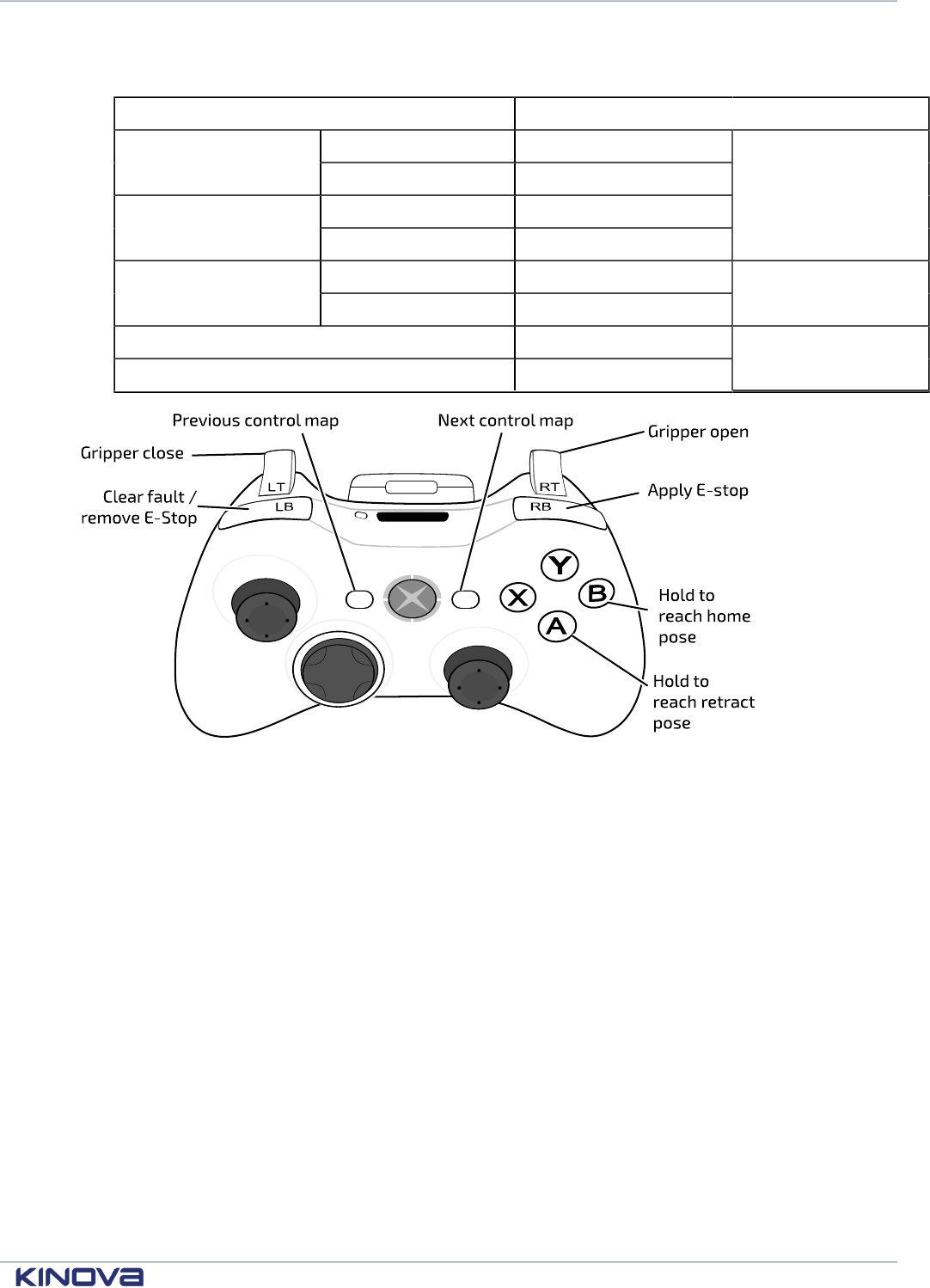
Kinova® Gen3 Ultra lightweight robot User Guide 43
Table 12: General control map elements (common controls applying to ALL maps)
Action Control
Retract pose A (hold down)
Reach defined pose
Home pose B (hold down)
previous View button
Navigate controller maps
next Menu button
button
close Left
Gripper command
open Right
trigger
Clear fault or remove E-Stop Left
Stop robot Right
bumper
Figure 22: General control map elements with Xbox gamepad
Twist linear map
Twist linear is the default gamepad map when the robot is turned on and the controller is
connected. In this mode the tool is translated in space with respect to the configured Cartesian
translation frame (by default the base frame). The tool orientation does not change in this map. The
user controls the linear velocity of the tool, including the linear speed.
+1 514-277-3777 kinovarobotics.com
© 2022 Kinova inc. All rights reserved.
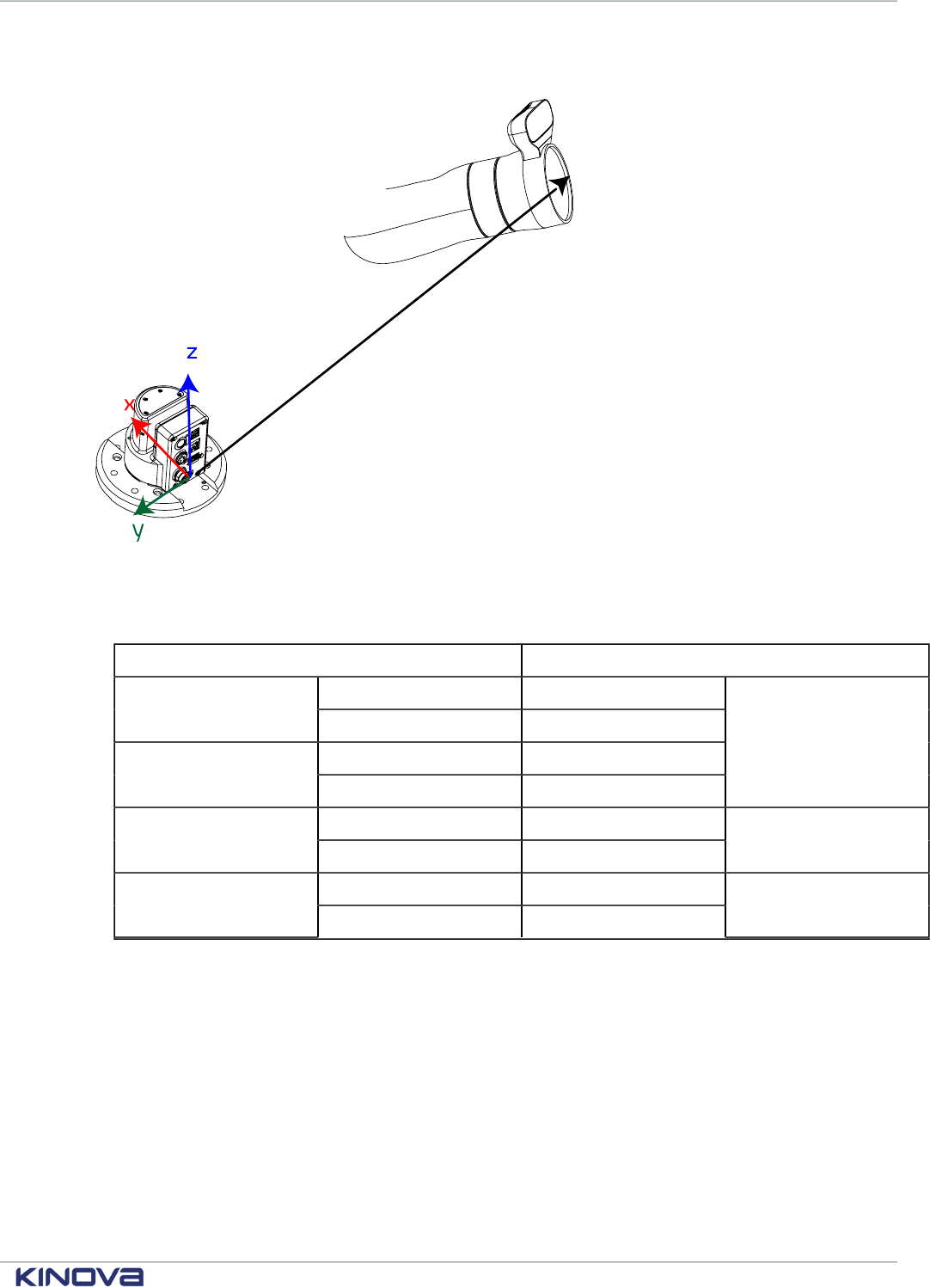
Kinova® Gen3 Ultra lightweight robot User Guide 44
-->
Table 13: Twist linear - general controls plus
Action Control
- downCartesian X translation
+ up
+ leftCartesian Y translation
- right
Left stick
- downCartesian Z translation
+ up
Right stick
decrease downSpeed
increase up
D-pad
+1 514-277-3777 kinovarobotics.com
© 2022 Kinova inc. All rights reserved.
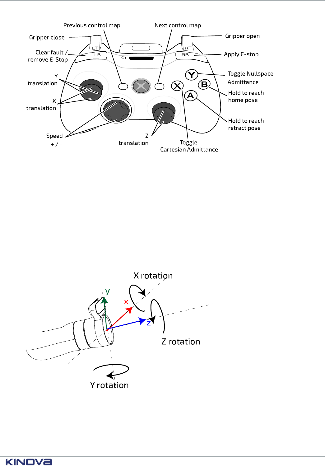
Kinova® Gen3 Ultra lightweight robot User Guide 45
Figure 23: Twist linear controls with Xbox gamepad
Twist angular map
The twist angular map is used to change the orientation of the gripper/tool without translating the gripper/
tool.
Twist angular can be thought of as a companion to the Twist linear control map. In Twist linear,
the tool is translated with respect to the configured Cartesian translation frame while leaving
the orientation unchanged. In Twist angular, the control is pure rotation of the tool within the
configured Cartesian orientation frame (by default the tool reference frame), around the three axes
of that frame. The user controls the angular velocity of the tool in relation to those three axes.
+1 514-277-3777 kinovarobotics.com
© 2022 Kinova inc. All rights reserved.
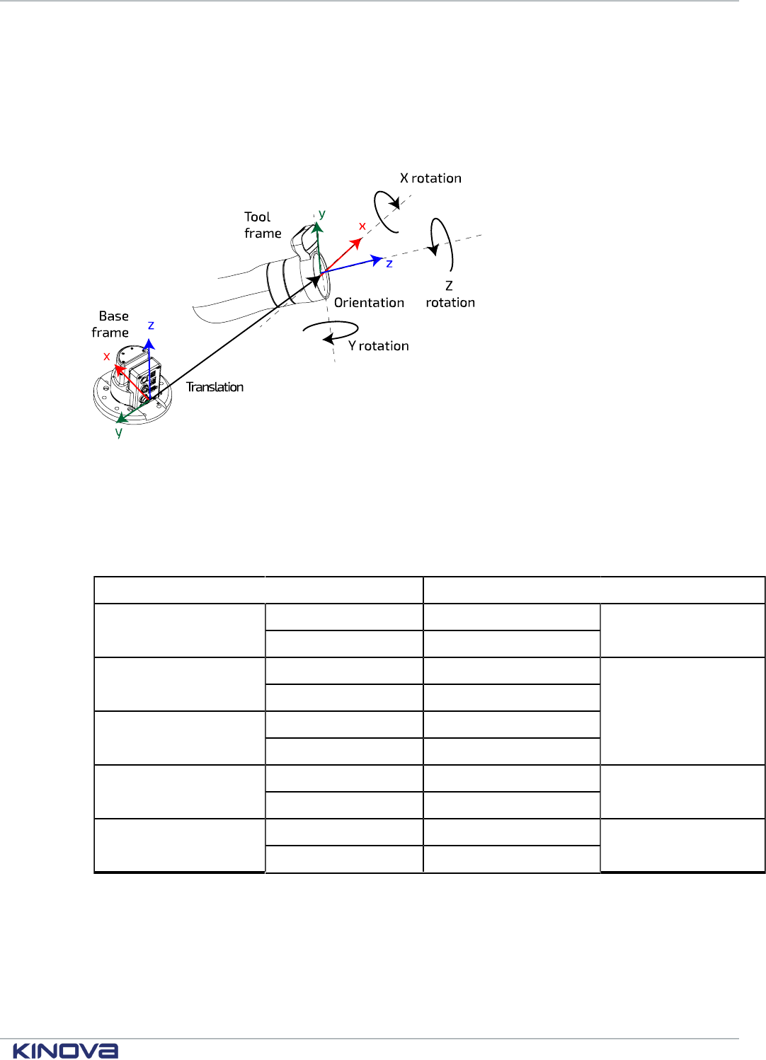
Kinova® Gen3 Ultra lightweight robot User Guide 46
Twist linear and Twist angular together specify a twist (consisting of three linear velocity terms and
three angular velocity terms) to be applied to the end effector (Cartesian control).
Table 14: Twist angular - general controls plus:
Action Control
Cartesian X
Toggle admittance
Nullspace Y
button
- left
Cartesian Y rotation
+ right
- down
Cartesian X rotation
+ up
L stick
- left
Cartesian Z rotation
+ right
R stick
decrease downSpeed
increase up
D-pad
+1 514-277-3777 kinovarobotics.com
© 2022 Kinova inc. All rights reserved.
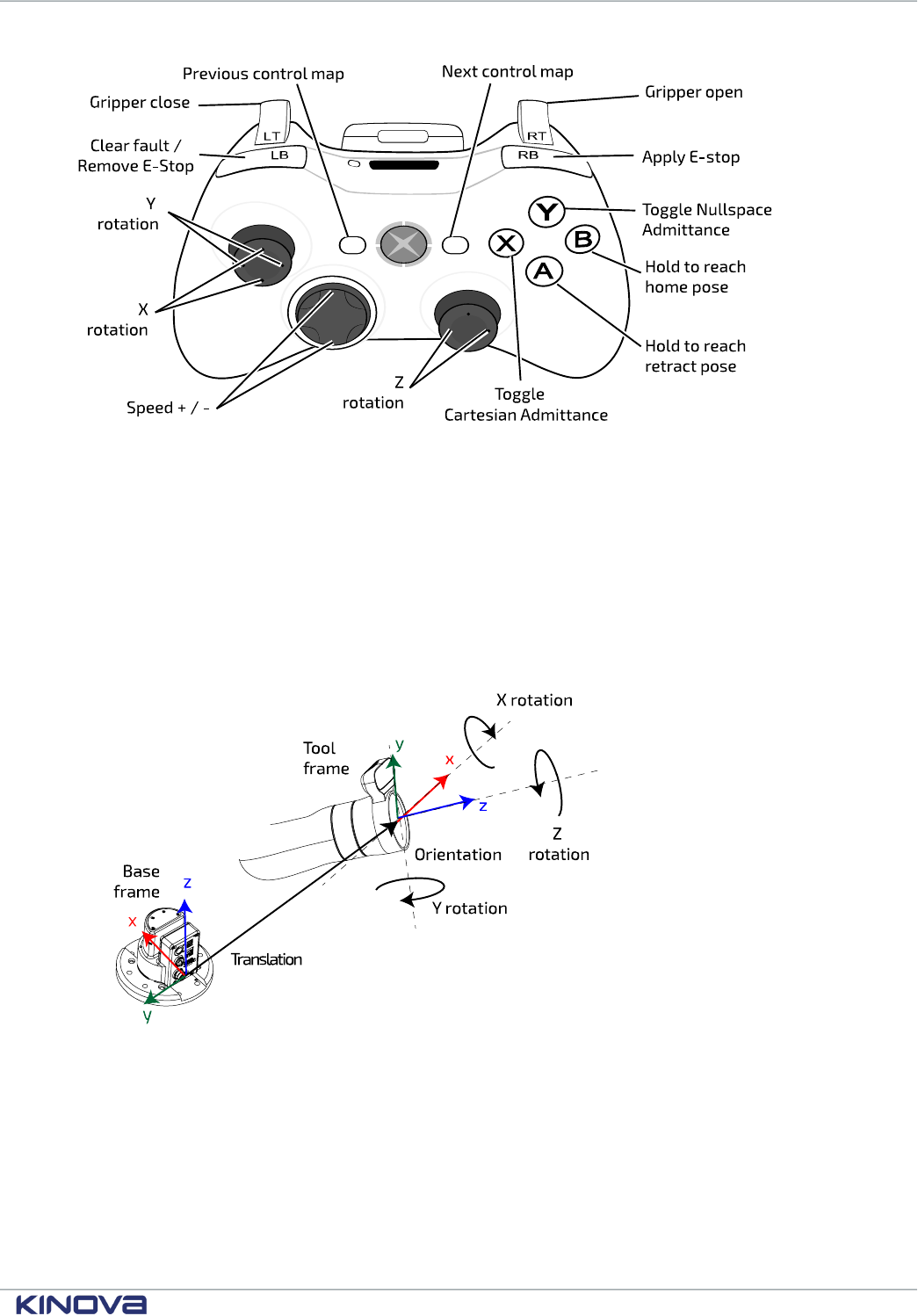
Kinova® Gen3 Ultra lightweight robot User Guide 47
Figure 24: Twist angular controls with Xbox gamepad
Twist combined map
Twist combined brings together the two Twist control maps into one map so that Cartesian
translation and orientation can be controlled from the same map. Instead of toggling to a
completely new map, the orientation controls can be accessed by pushing in the left and right sticks
while moving the stick.
+1 514-277-3777 kinovarobotics.com
© 2022 Kinova inc. All rights reserved.
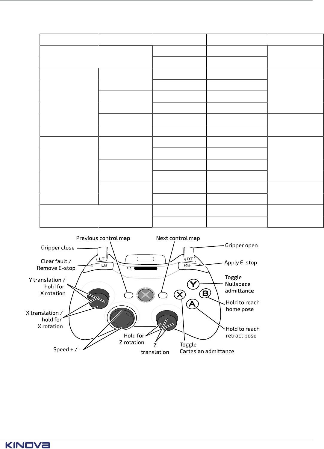
Kinova® Gen3 Ultra lightweight robot User Guide 48
Table 15: Twist combined - general controls plus:
Action Control
Cartesian X
Toggle admittance
Nullspace Y
button
- down
X
+ up
+ left
Y
- right
L stick
- down
Cartesian
translation
Z
+ up
R stick
- hold in + down
X
+ hold in + up
- hold in + left
Y
+ hold in + right
L stick
- hold in + left
Cartesian rotation
Z
+ hold in + right
R stick
decrease downSpeed
increase up
D-pad
Figure 25: Twist combined controls with Xbox gamepad
Joint map
The joint map allows actuators to be chosen and moved one by one.
Joint control offers direct control of the rotational movement of the joint actuators. In this mode
you can toggle through the joints (actuators) one by one, starting with the first and going through in
increasing order. On reaching the last actuator, it will then cycle back to the first. The joint angular
speed (ω) can be controlled.
+1 514-277-3777 kinovarobotics.com
© 2022 Kinova inc. All rights reserved.

Kinova® Gen3 Ultra lightweight robot User Guide 49
Table 16: Joint - general controls plus:
Action Control
Toggle admittance Joint X button
ω-
left
Joint speed
ω+
right
L stick
increase up
Speed
decrease down
Previous left
Navigate joints
Next right
D-pad
Figure 26: Joint controls with Xbox gamepad
Wrench Force control map
In this control mode, the force portion of a wrench applied at the end effector can be specified by
the user.
Table 17: Wrench Force - general controls plus:
Action Control
- X -
Wrench force command X
+ X +
- Y -
Wrench force command Y
+ Y +
L stick
- Z -
Wrench force command Z
+ Z +
R stick
+1 514-277-3777 kinovarobotics.com
© 2022 Kinova inc. All rights reserved.
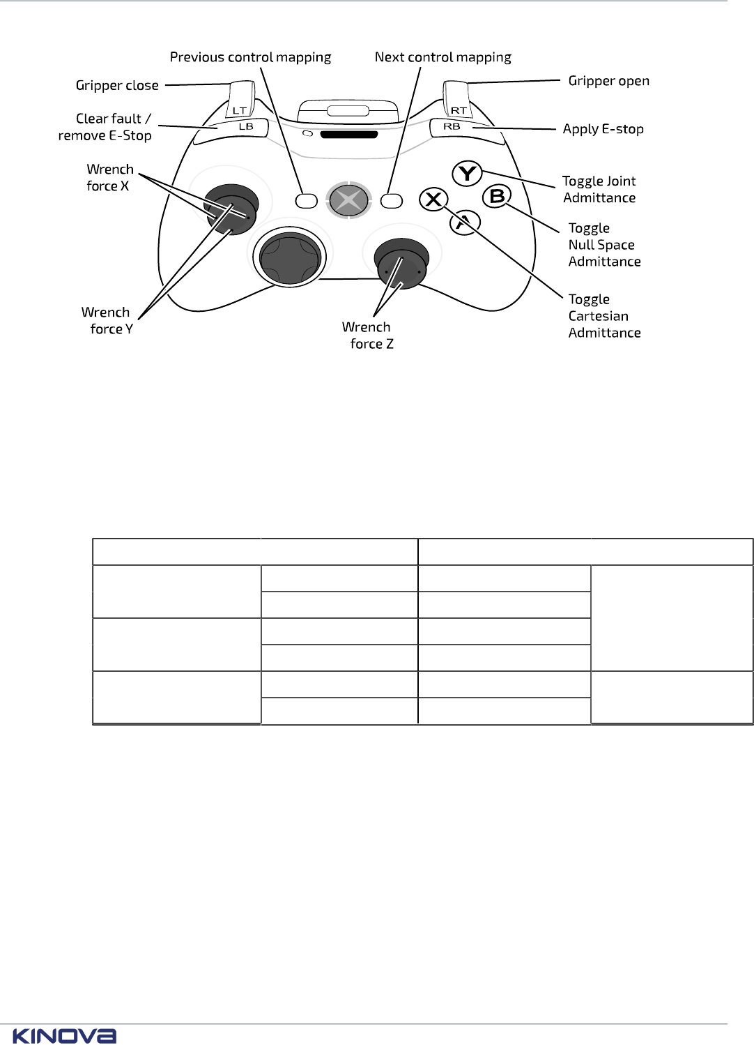
Kinova® Gen3 Ultra lightweight robot User Guide 50
Figure 27: Wrench Force control with Xbox gamepad
Wrench Torque control map
In this control mode, the torque portion of a wrench applied at the end effector can be specified by
the user.
Wrench Force and Wrench Torque together specify the wrench (consisting of three force terms and
three torque terms) to be applied to the end effector at the end effector.
Table 18: Wrench Torque - general controls plus:
Action Control
- X -
Wrench torque
command X
+ X +
- Y -
Wrench torque
command Y
+ Y +
L stick
- Z -
Wrench torque
command Z
+ Z +
R stick
+1 514-277-3777 kinovarobotics.com
© 2022 Kinova inc. All rights reserved.
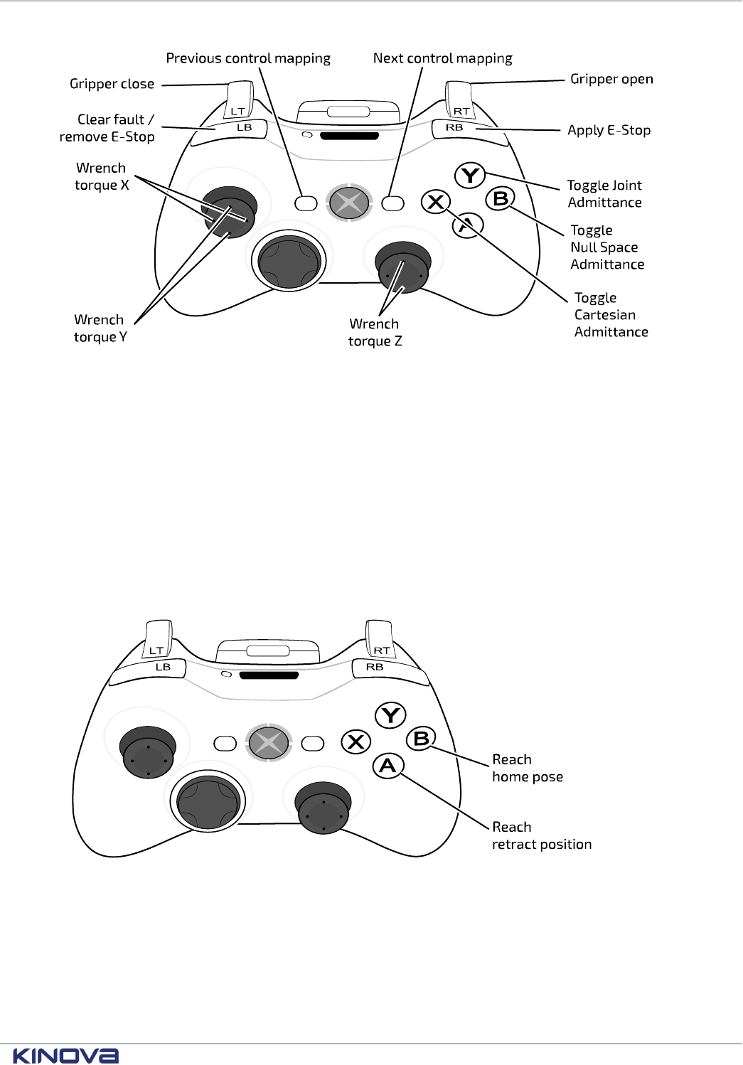
Kinova® Gen3 Ultra lightweight robot User Guide 51
Figure 28: Wrench Torque control with Xbox gamepad
Home and retract positions
Pre-configured Xbox gamepad maps set aside two buttons to move the robot to the home and retract
positions of the robot.
The robot includes two pre-configured poses that can be reached using the Xbox gamepad.
The home position sets the robot into a convenient "ready" position. The home position is reached
by holding down the B button on the Xbox gamepad.
The retract position folds the robot up into a compact pose. This can be a useful position to out the
robot into for periods when it will not be in use. The retract position is reached by holding down the
A button on the Xbox gamepad.
Figure 29: Reach home and retract controls
Putting the robot into admittance using the interface buttons
The wrist buttons on the sides of the interface module can be used to put the robot into admittance modes.
Three different admittance modes are accessible, depending on the buttons used.
+1 514-277-3777 kinovarobotics.com
© 2022 Kinova inc. All rights reserved.
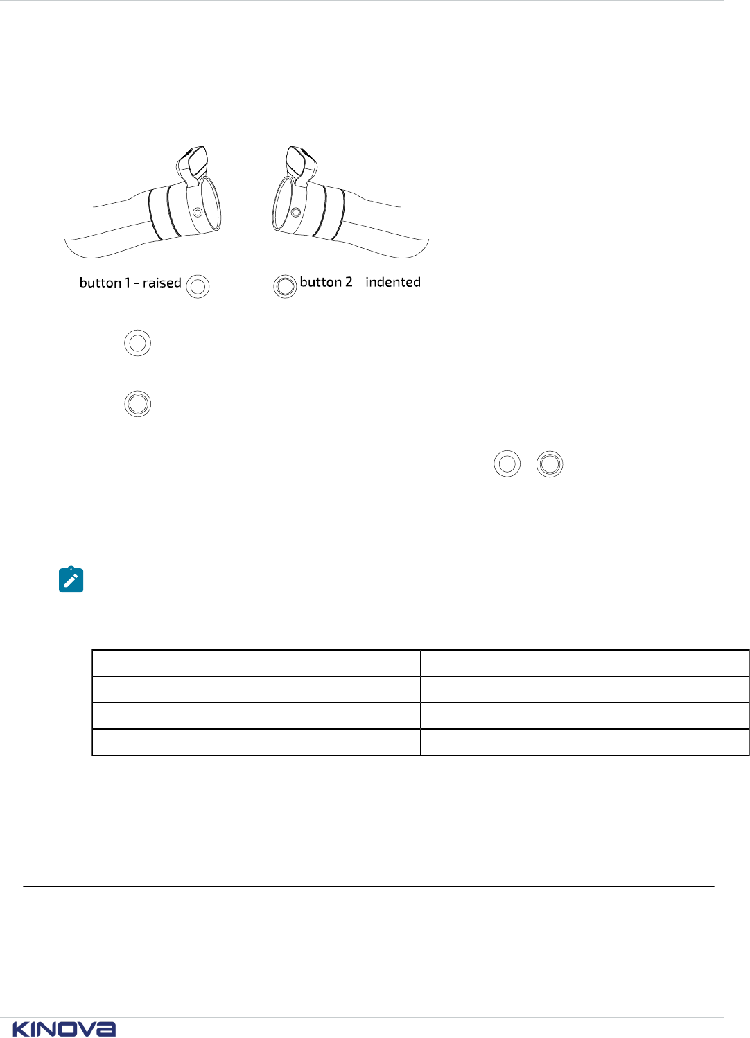
Kinova® Gen3 Ultra lightweight robot User Guide 52
The interface module has two buttons on its side that by default can be used to temporarily put the
robot into admittance. This can be a convenient way to take ahold of the robot and move it into a
desired position, or to explore the flexibility of the robot at a particular position.
The two interface module buttons each offer access to one admittance mode.
Figure 30: Interface module admittance buttons
Button 1 ( ) has a raised solid circle shape. This button by itself is used to activate Cartesian
admittance, in which the end effector of the robot moves in response to force exerted on it.
Button 2 ( ) has an indented or ring shape. This button by itself is used to activate joint
admittance, in which the joints of the robot rotate freely in response to forces exerted on them.
For the 7 DoF model, button 1 and button 2 can be used together ( + ) to activate null space
admittance. In this mode the end effector stays in a fixed position and orientation, while the other
joints move within the null space available at the given end effector (seven degrees of freedom to
specify six coordinates of position and orientation gives a free degree of liberty to move within
different solutions of the inverse kinematics of a given pose).
Note: Since the 6 DoF robot model does not have this redundant degree of freedom, null
space admittance is not supported on the 6 DoF model.
Table 19: Wrist button admittance modes map
Button Effect
button 1 enter Cartesian admittance
button 2 enter joint admittance
button 1 + button 2 enter null space admittance (7 DoF robot only)
To engage one of the admittance modes, hold down the appropriate button(s) and exert a moderate
amount of force on the robot. The robot will be in admittance mode as long as the button is held
down. When the button is released, the robot will no longer be in admittance mode and will return
to the previously engaged control mode.
Connecting a computer to the robot
Connection options
The robot can be connected to a computer via either wired Ethernet or Wi-Fi. Wired connections can be
point to point or over a small local area network.
+1 514-277-3777 kinovarobotics.com
© 2022 Kinova inc. All rights reserved.
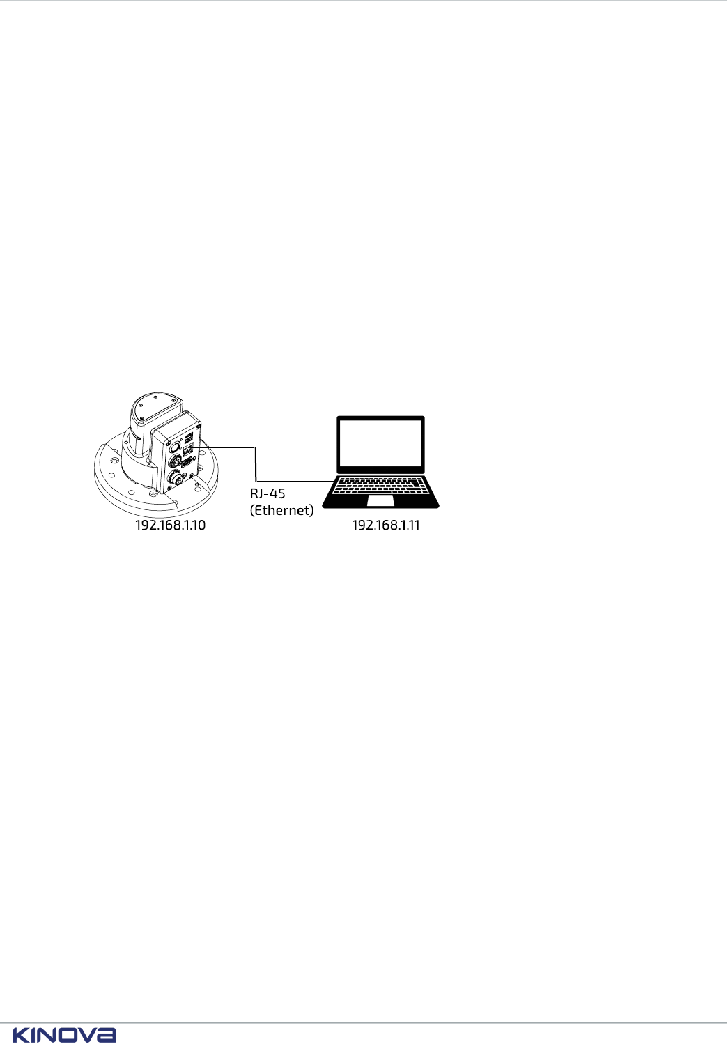
Kinova® Gen3 Ultra lightweight robot User Guide 53
There are two ways of connecting a computer to the robot arm:
• Ethernet (direct or over a local network)
• Wi-Fi
Connecting a computer to the robot via Ethernet (for the first time)
Describes the steps to connect a computer to the robot via a wired connection for the first time. This
procedure requires some configuration of the computer's network adapter.
About this task
This procedure is required to connect a computer to the computer for the first time via a wired Ethernet
connection. This requires some configuration of the computer. The following procedure describes details for
Windows 10. The details will be somewhat different for other OS platforms, but the high level steps will be
the same.
Procedure
1. Connect an RJ-45 Ethernet cable from your computer's wired network adapter to the base
Ethernet port.
+1 514-277-3777 kinovarobotics.com
© 2022 Kinova inc. All rights reserved.
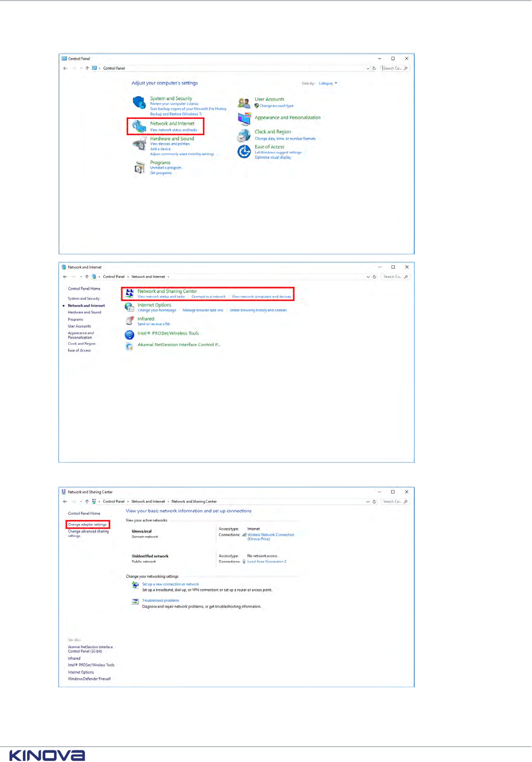
Kinova® Gen3 Ultra lightweight robot User Guide 54
2. On your computer, open Control Panel > Network and Internet > Network and Sharing Center
3. Select Change adapter settings
4. Select wired Ethernet adapter (i.e. Local Area Connection) and choose Properties.
+1 514-277-3777 kinovarobotics.com
© 2022 Kinova inc. All rights reserved.
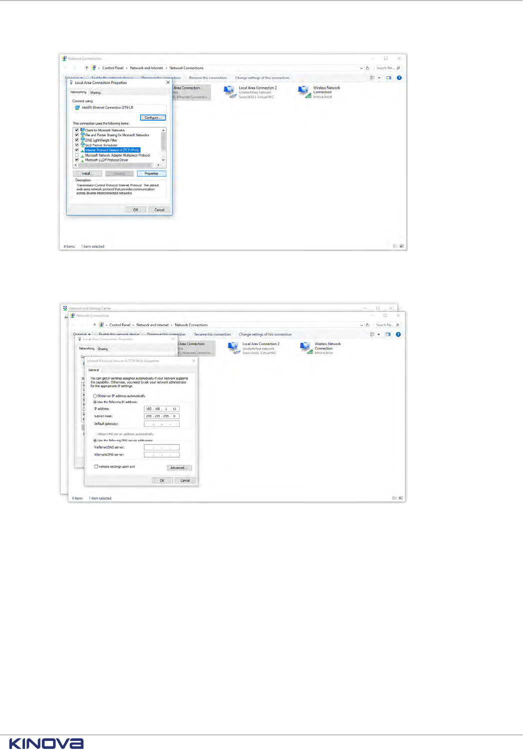
Kinova® Gen3 Ultra lightweight robot User Guide 55
5. Select Internet Protocol Version 4 (TCP/IPv4) and choose Properties.
6. Select Use the following IP address and enter IPv4 address and the Subnet mask.
IPv4 address is 192.168.1.XX, where XX is another from 11 and larger. Subnet mask is
255.255.255.0
7. Press OK.
Results
Your computer is now connected physically to the robot and ready to communicate.
What to do next
You can now access the Web App.
Kinova® Kortex™ Web App
This section is an overview of the Web App. The Web App allows you to interact with the robot and perform
basic tasks wuthout using programming commands.
The Web App provides a HTML Web browser based GUI to interact with the arm and perform basic
tasks without using programming commands.
+1 514-277-3777 kinovarobotics.com
© 2022 Kinova inc. All rights reserved.
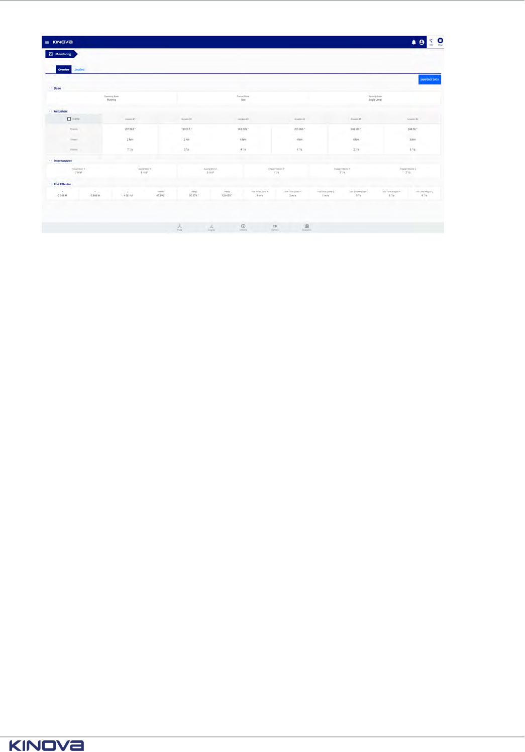
Kinova® Gen3 Ultra lightweight robot User Guide 56
The Web App allows users to control and configure the robot via the GUI.
This includes:
• Real-time control of the robot in different modes using different virtual joysticks
• Setting the arm into admittance modes to manipulate the arm using external forces / torques
• Viewing the feed from the Vision module color sensor
• Configuring
º robot performance parameters and safety thresholds
º protection zones
º network settings
º backup management
º user profiles
• Reading
º system information
º notifications
• Defining robot poses and trajectories
• Managing control mappings for physical controllers
• Monitoring robot parameters
• Upgrading the robot firmware
The Web App can be run from a desktop or laptop PC connected by wired connection to the robot,
or from any device on the same local network. Devices include desktops, laptops, smartphones, and
tablets. The local network type includes local Wi-Fi neworks.
The Web App is described in detail in the Kinova
®
Kortex™ Web App User Guide section.
Accessing the Kinova
®
Kortex™ Web App
This section describes how to launch the Web App.
Before you begin
You should be using a computer that is connected to the robot either over a wired (direct or over local area
network) or wireless connection and you should have the IP address of the robot on the network over which
you are connected.
+1 514-277-3777 kinovarobotics.com
© 2022 Kinova inc. All rights reserved.
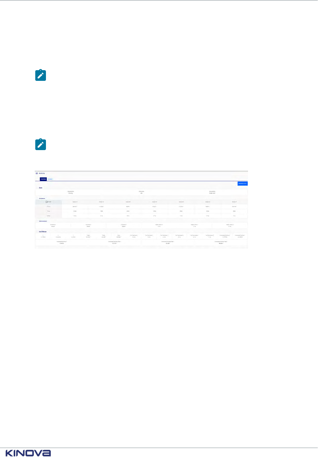
Kinova® Gen3 Ultra lightweight robot User Guide 57
About this task
Procedure
1. From the computer web browser, enter the appropriate IP address for the arm base to access
the Web App.
Note: By default, the IP address to use here is:
• 192.168.1.10
If you have configured the robot with a different IP address so that the computer and
robot are both connected to the same local area network, whether wired or over Wi-Fi,
use the newly configured IP address.
2. If the connection between the arm and computer is configured correctly, the Web application
should launch and present a login window. In the login window, enter the following credentials:
Note: By default, the username-password pair is admin/admin.
3. Click CONNECT. The application will initialize. If all is successful, the application will open to a
Monitoring screen that displays live parameters for the robot.
Teaching mode
Teaching mode provides a way to build sequences of robot movements by moving the robot by hand uisng a
combination of the Web App and the wrist buttons on the interface module.
Teaching Mode support provides a user-friendly interface to build sequences by moving the robot
by hand using admittance modes and capturing pose, joint, and gripper snapshots. This sequence
can be edited and configured.
This is done using a combination of the Web App Actions page and the wrist buttons on the
interface module.
Teaching mode is entered using the Web App. Entering teaching mode changes the map of the wrist
buttons so that the buttons can be used to capture snapshots.
For more details, see the Web App Actions page documentation.
Changing the robot wired connection IP address and connecting the robot
to a LAN
Describes steps to change the robot's wired connection IP address and connect the robot to a local area
network (LAN).
+1 514-277-3777 kinovarobotics.com
© 2022 Kinova inc. All rights reserved.

Kinova® Gen3 Ultra lightweight robot User Guide 58
Before you begin
You need to have already to your computer via Ethernet cable and the computer's local network adapter port.
You will need information about the available IP addresses on the local area network (LAN) to which you want
to connect the robot.
About this task
This procedure is used to configure the robot so that you can connect a computer to the robot remotely over
your local area network.
Note: For security reasons, we do not recommend connecting the robot to a WAN. The
network should be a simple local area network with low traffic.
Procedure
1. Open the Web application and go to the Networks page. Open the Ethernet tab.
2. Modify the IPv4 address, IPv4 subnet mask, and IPv4 gateway to match an available IP address
with the IP address range of your network.
Note: Once you modify the robot network parameters, your client computer will lose
connection with the robotic arm.
3. Physically disconnect the robot from your computer and connect it via Ethernet cable to your
LAN at a network switch.
4. Restore IP settings compatible with the LAN on your computer's local network adapter and
connect your computer physically to the LAN.
5. From your computer, ping the robot at its newly configured robot IP address to confirm that
communication is established.
What to do next
From your computer web browser, enter the new robot IP address to access the Web App.
Connecting a computer to the robot via Wi-Fi
This section describes how to connect a computer to the robot via Wi-Fi.
Before you begin
You will need to have a wired connection between the computer and robot prior to carrying out this
procedure. The Wi-Fi router will need to be set to broadcast its SSID so that the robot can find the network.
The router will also need to be configured to accept new devices. You will also need the Wi-Fi password.
About this task
The robot features an integrated Wi-Fi adapter. This allows the arm to connect to a local Wi-Fi connection.
Once this connection is established, other devices on the same Wi-Fi network can then connect to the robot
wirelessly using the IP address assigned for the robot on the wireless network.
Procedure
1. On a computer connected to the robot via wired Ethernet, open the Web App and connect to the
robot.
2. Under the Configurations page group, select Wireless & Networks in the main navigation panel
of the Web App to go to the Wireless & Networks page.
3. Once on the page, select the Wi-Fi tab.
+1 514-277-3777 kinovarobotics.com
© 2022 Kinova inc. All rights reserved.

Kinova® Gen3 Ultra lightweight robot User Guide 59
4. The Wi-Fi tab will list all of the detected Wi-Fi networks. Choose one of the networks, and click
the corresponding Connect text button.
Note: It is not recommended to connect to Wi-Fi networks which are potentially
insecure. Security settings of at least WPA2 are recommended.
5. A pop-up window will appear to sign in to the network, with information about the signal
strength and security settings. Enter the password for the network and click the CONNECT
button.
Note: A Connect Automatically toggle is available here. Toggling this on will allow the
robot base to automatically connect to the wireless network using the previously entered
password whenever the robot is powered on.
6. Take note of the wireless network IPv4 address that the robot obtains after clicking the
CONNECT button.
7. On any wireless device (laptop, tablet, smartphone) connected to the same Wi-Fi network,
open a Web browser and type the IP address that the robot obtained at Step 6 (This address
corresponds to the robot's address on the Wi-Fi network).
8. The Web App login screen will appear. At the login screen, enter the appropriate user name and
password, and click the CONNECT button.
Results
You are now connected to the Web App through the Wi-Fi network adapter of the robot. You can now
configure, monitor, and control the robot wirelessly via either the Web App or via API control.
Note: A Wi-Fi connection is not recommended for 1 kHz (low-level) control of the robot due
to potential latency issues - a wired connection must be used for this purpose.
Assigning a static IP address for Wi-Fi to the robot
This sectin describes how to assign a static IP address to the robot for Wi-Fi connection. This makes it
possible to always connect to the robot over Wi-Fi using the same IP address.
Before you begin
You will already need to have connected over Wi-Fi to the robot.
About this task
A previous section of the document describes how to connect to the robot via Wi-Fi. By default, when
conencting, the robot will be assigned an IP address dynamically by the router. However, this means that
in general the robot will receive different wireless IP addresses on different sessions. Sometimes, it will
be advantageous to fix an IP address on that Wi-Fi network. You will need to obtain the MAC address
for the robot base and use this to configure an assigned static IP in your Wi-Fi router. Depending on your
organization, local IT may need to perform this step for you.
Procedure
1. Connect to the robot via the Web App, logging in to the application.
2. Navigate to the System Information page in the Systems page group.
3. Select the Arm tab, and then open the Base section on this tab.
4. Take note of the MAC address information. You will need this to configure a static IP address.
5. Login as an administrator to your Wi-Fi router via the web interface.
6. The details will differ from router to router. Find the MAC address entry for the robot base
in the LAN settings. Change the lease type to static and either choose or manually enter an
available IP address from the valid range. Apply the changes.
+1 514-277-3777 kinovarobotics.com
© 2022 Kinova inc. All rights reserved.

Kinova® Gen3 Ultra lightweight robot User Guide 60
Results
The router is now set to assign the same configured IP address every time the robot connects to Wi-Fi.
What to do next
On any wireless device (laptop, tablet, smartphone) connected to the same Wi-Fi network, you will be able to
connect to the robot via the Web App by entering the assigned IP in a browser. Similarly you will be able to use
the static IP address in applications developed using the API.
+1 514-277-3777 kinovarobotics.com
© 2022 Kinova inc. All rights reserved.
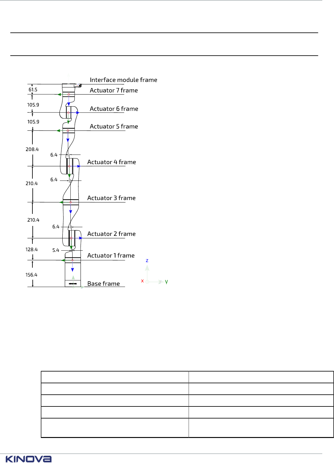
Kinova® Gen3 Ultra lightweight robot User Guide 61
Dimensions, specifications, and capabilities
Schematic and dimensions - 7 DoF spherical wrist
Schematic diagram of the 7 DoF robot and the key physical dimensions of the robot.
Figure 31: 7 DoF spherical wrist frames definition and dimensions
The image above defines reference frames for the base, joints (when all joint angles = 0) and end
effector. Each frame is defined in terms of the previous frame via a transformation matrix. The
diagram also indicates the link lengths and lateral offset values (measurements in mm).
The maximum reach of the robot, as defined by the distance from the shoulder (actuator 2 frame) to
the interface module frame, is 90.2 cm.
Table 20: 7 DoF spherical wrist robot geometric parameters
Description Length (mm)
Base to actuator 1 156.4
Base to shoulder (actuator 2) 284.8
First half upper arm length (actuator 2 to actuator 3) 210.4
Second half upper arm length
(actuator 3 to actuator 4)
210.4
+1 514-277-3777 kinovarobotics.com
© 2022 Kinova inc. All rights reserved.
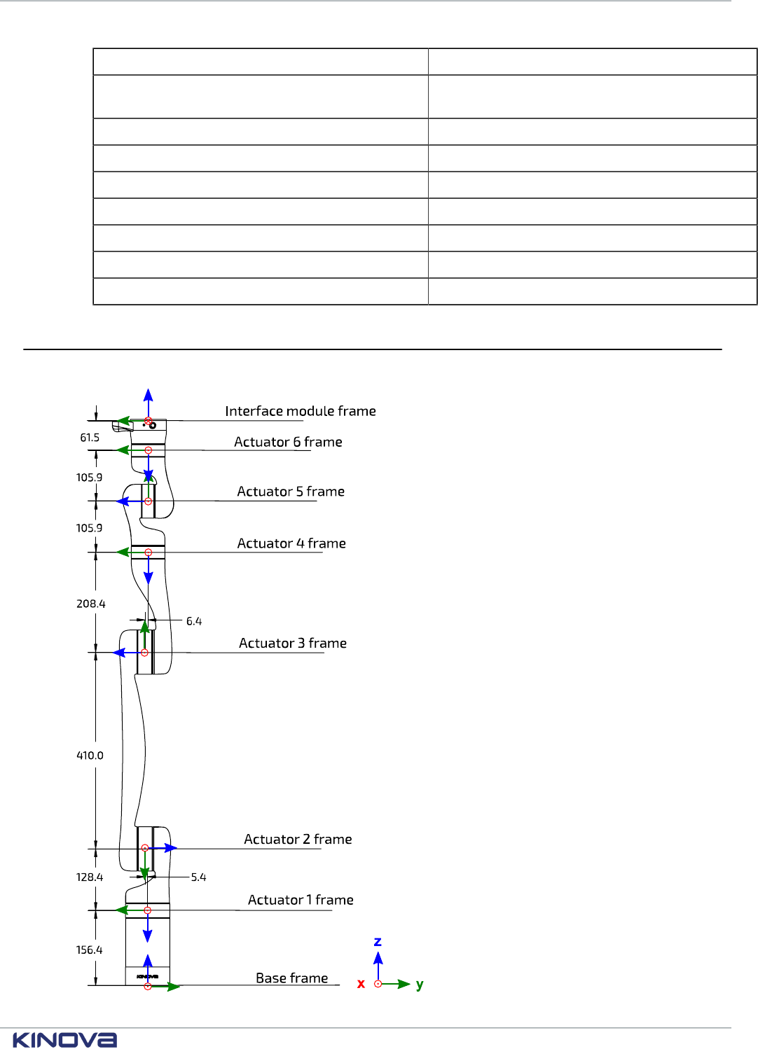
Kinova® Gen3 Ultra lightweight robot User Guide 62
Description Length (mm)
Forearm length - elbow to
wrist (actuator 4 to actuator 5)
208.4
First wrist length (actuator 5 to actuator 6) 105.9
Second wrist length (actuator 6 to actuator 7) 105.9
Last actuator to interface module 61.5
Joint 1-2 offset 5.4
Joint 2-3 offset 6.4
Joint 3-4 offset 6.4
Joint 4-5 offset 6.4
Schematic and dimensions - 6 DoF spherical wrist
Schematic diagram of the 6 DoF robot and the key physical dimensions of the robot.
+1 514-277-3777 kinovarobotics.com
© 2022 Kinova inc. All rights reserved.
Kinova® Gen3 Ultra lightweight robot User Guide 63
Figure 32: 6 DoF spherical wrist frames definition and dimensions
The image above defines reference frames for the base, joints (when all joint angles = 0) and end
effector. Each frame is defined in terms of the previous frame via a transformation matrix. The
diagram also indicates the link lengths and lateral offset values (measurements in mm).
The maximum reach of the robot, as defined by the distance from the shoulder (Actuator 2 frame)
to the end effector frame, is 89.1 cm.
Table 21: 6 DoF spherical wrist robot geometric parameters
Description Length (mm)
Base to actuator 1 156.4
Base to shoulder 284.8
Upper arm length 410.0
Forearm length (elbow to wrist) 208.4
First wrist length 105.9
Second wrist length 105.9
Last actuator to interface module 61.5
Joint 1-2 offset 5.4
Joint 3-4 offset 6.4
Technical Specifications
Technical specifications for the Kinova
®
Gen3 Ultra lightweight robot, categorized for ease of reference. Some
of these also appear within the main body of the text.
Table 22: Safety / Security
Feature Detail
Safety alarm (power monitor) ≥ 10A (maximum current)
Position monitor default and user-defined protection zones
Thermal monitor
warning / shutdown above
maximum operating temperature
Table 23: Environmental
Parameter Value(s)
-30 °C to 35°C (operating)
Temperature
-30 °C to 50 °C (storage)
Relative humidity (non-condensing) 15% to 90% (operating)
Pressure 70 kPa to 106 kPa *
Sound pressure level (nominal) < 55.5 dBA
Universal Power Supply (external) 300 W
+1 514-277-3777 kinovarobotics.com
© 2022 Kinova inc. All rights reserved.
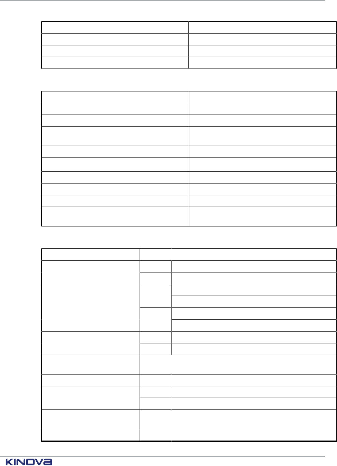
Kinova® Gen3 Ultra lightweight robot User Guide 64
Parameter Value(s)
Power supply input voltage 100 - 240 VAC
Power supply input frequency 50 - 60 Hz
Power supply ingress protection IP42
Table 24: Controller (base)
Feature Detail
power indicator blue LED
status indicator red/amber/green LED
USB 2.0 (two ports)
Xbox gamepad connect; 1 A charging
(top), 500 mA USB peripherals (lower)
Gigabit Ethernet (RJ-45) for development PC connection
Wi-Fi (IEEE 802.11a/b/g/n)
Kinova
®
Kortex™ Web App and API
HDMI 1.4a (Internal use only)
circular connector [Binder-USA 09 0463 90 19] Internal use only
circular connector [Lumberg 0317 08] power
sensors
voltage, current, temperature,
accelerometer and gyroscope
Table 25: Robot
Parameter Value(s)
7 DoF 8.2 kg
Mass (without gripper
and with vision module)
6 DoF 7.2 kg
mid-range continuous; no gripper: 4.0 kg
7 DoF
full-range continuous; no gripper: 2.0 kg
mid-range continuous; no gripper: 4.0 kg
Payload
6 DoF
full-range continuous; no gripper: 2.0 kg
7 DoF 902 mm
Maximum reach (fully extended)
6 DoF 891 mm
Maximum Cartesian
translation speed
50 cm/s
Degrees of freedom 7 DoF, 6 DoF
small: qty 3 (small)
Actuators
large: qty 4 (7 DoF), 3 (6 DoF)
Wrist interaction buttons
qty 2 (user-configurable; default for
admittance control; teaching mode controls)
Power supply voltage 24 VDC (nominal, 20 to 30 V)
+1 514-277-3777 kinovarobotics.com
© 2022 Kinova inc. All rights reserved.

Kinova® Gen3 Ultra lightweight robot User Guide 65
Parameter Value(s)
Carbon fiber shell
Materials
Aluminum
100 Mbps Ethernet for real-time 1 kHz control
Communciations and control
100 Mbps Ethernet for Vision module / expansion
Table 26: Actuators
Feature Value(s)
Sensors
current sensors (motor), temperatures
(motor), voltage, torque, position
Table 27: Interface module
Feature Function
Vision module color and depth sensing
Wrist status LEDs admittance mode indication
Wrist pushbuttons admittance modes; teaching mode
Kinova internal end-effector interface connector (Internal use only)
10-pin spring-loaded connector RS-485 (compatible with Robotiq Adaptive Grippers)
100 Mbps Ethernet
UART (3.3V)
I
2
C (3.3V)
GPIO (3.3V, qty 4)
24V @ 0.5A
20-pin user expansion connector
[AVX/Kyocera 046288020000846+]
3.3V @ 0.1A for signaling
Sensors accelerometer and gyroscope, voltage, temperature
Table 28: Vision
Feature Detail
Depth sensor
480 x 270 (16:9) @ 30, 15, 6 fps
424 x 240 (16:9) @ 30, 15, 6 fps
FOV: 72 ± 3° (diagonal)
minimum depth distance - 18 cm
+1 514-277-3777 kinovarobotics.com
© 2022 Kinova inc. All rights reserved.
Kinova® Gen3 Ultra lightweight robot User Guide 66
Feature Detail
Color sensor
1920 x 1080 (16:9) @ 30, 15 fps; FOV 47 ± 3°
(diagonal)
1280 x 720 (16:9) @ 30, 15 fps ; FOV 60 ± 3°
(diagonal)
640 x 480 (4:3) @ 30, 15 fps; FOV 65 ± 3°
(diagonal)
320 x 240 (4:3) @ 30, 15 fps; FOV 65 ± 3°
(diagonal)
focusing range - 30 cm to ∞
* subject to change
Sensors
The robot contains a number of different sensors. There are sensors in the base, actuators, and interface
module. Sensors data can be accessed using the cyclic communications with the base.
The robot contains a number of sensors to provide feedback on the status of the robot. This data is
used by the robot for internal monitoring and control.
The robot components contain the following sensors:
Base sensors
• Voltage
• Current
• Temperature
• 6-axis accelerometer/gyroscope
Actuator sensors
• Motor phases current sensors (one per phase)
• Motor phases temperature sensors (one per phase)
• CPU temperature sensor
• Input voltage sensor
• Hall effect sensors for BLDC motor drive
• Absolute rotary position encoder
• Incremental rotary position encoder
• Applied torque
Interface module sensors
• Temperature sensor (CPU, accelerometer and dedicated)
• 6-axis accelerometer/gyroscope
Access to sensors data
Data from some sensors can be read by users using the APIs or through the Monitoring page of the
Web Application.
The API method RefreshFeedback() in the BaseCyclic API returns a data structure with
readings from sensors in:
+1 514-277-3777 kinovarobotics.com
© 2022 Kinova inc. All rights reserved.

Kinova® Gen3 Ultra lightweight robot User Guide 67
• Base
• Actuators
• Interface
For detailed information on how to unpack this data in an application, see the BaseCyclic API
documentation on the Kinova
®
Kortex™ GitHub repository.
The following tables give more information about the sensor data.
Eective workspace
Description of the effective workspace of the robot. The effective workspace is the region in space reachable
by the tool.
Eective workspace overview
The effective workspace refers to the region in three-dimensional space which is reachable by the
robot tool. This is impacted by several factors, including the number and length of the links, the joint
ranges, and the shape of the links.
There are two definitions of effective workspace, the first being larger than the second.
1. Nominal (or reachable) workspace - the set of all locations in the three-dimensional space
reachable by the tool through at least one combination of end effector position and orientation
2. Dextrous workspace - the subset of the nominal workspace in which the tool still has the full
freedom to move, both in translation (three degrees of freedom) and in rotation (three degrees
of freedom)
Detailed information
The following graphic illustrates a two-dimensional cross-section of the nominal workspace for the
robot.
+1 514-277-3777 kinovarobotics.com
© 2022 Kinova inc. All rights reserved.
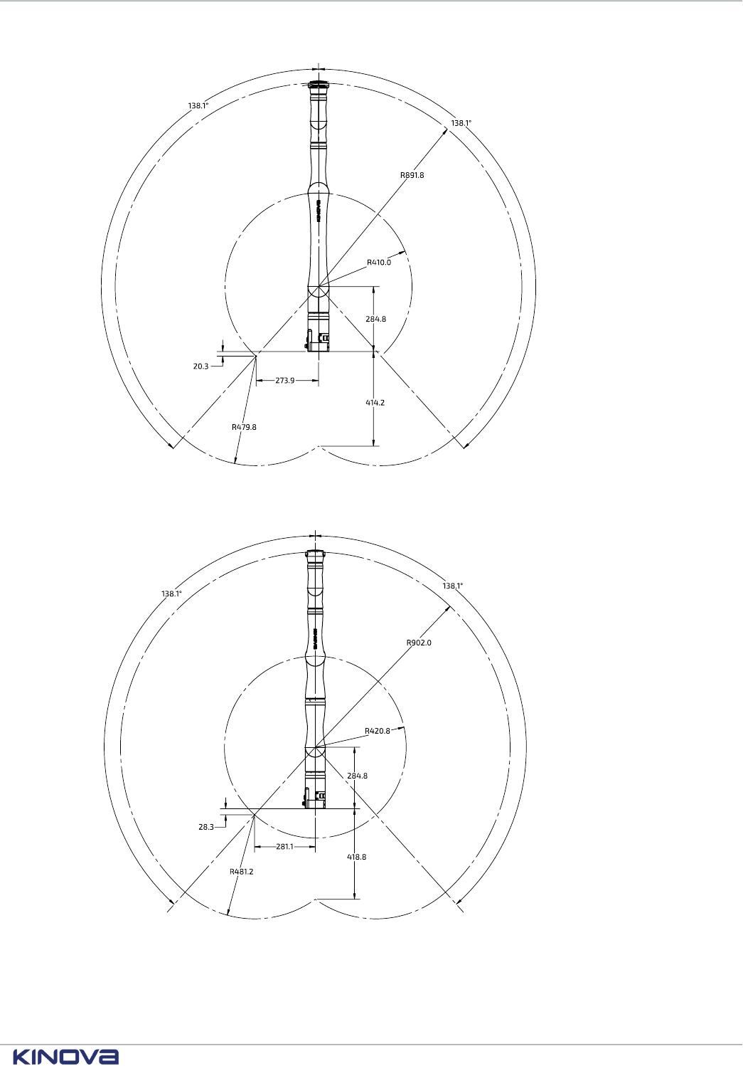
Kinova® Gen3 Ultra lightweight robot User Guide 68
Figure 33: 6 DoF robot nominal workspace (measurements in mm)
Figure 34: 7 DoF robot nominal workspace (measurements in mm)
+1 514-277-3777 kinovarobotics.com
© 2022 Kinova inc. All rights reserved.

Kinova® Gen3 Ultra lightweight robot User Guide 69
Payload vs. workspace
Describes the variation of payload over the workspace and depending on the type of use.
Overview
The payload of the robot is the maximum mass that the robot can hold up at the end effector. The
actuators must apply high torques. The payload is limited by the heat produced by the actuators.
The payload is limited by distance and duration because of the high torque heat that is produced.
This is generally not one constant figure, but will depend on a few factors.
• radial distance from the base - the payload will be highest closest to the base, and will go down as
the end effector gets farther out from the base axis.
• temporary vs. continuous - the robot will have a maximum payload that can be handled
temporarily for a short period of time. However, continued use of the arm with that payload
for an indefinite period will cause the arm to heat up, as the heat generated by the strain on
the actuator exceeds the rate at which heat can be dissipated. However, a smaller mass can be
handled for an indefninite period. This is referred to as the continuous payload limit.
The payload will also depend on whether a gripper is attached or not, with some of the payload
capability reduced to lift the weight of the gripper.
+1 514-277-3777 kinovarobotics.com
© 2022 Kinova inc. All rights reserved.
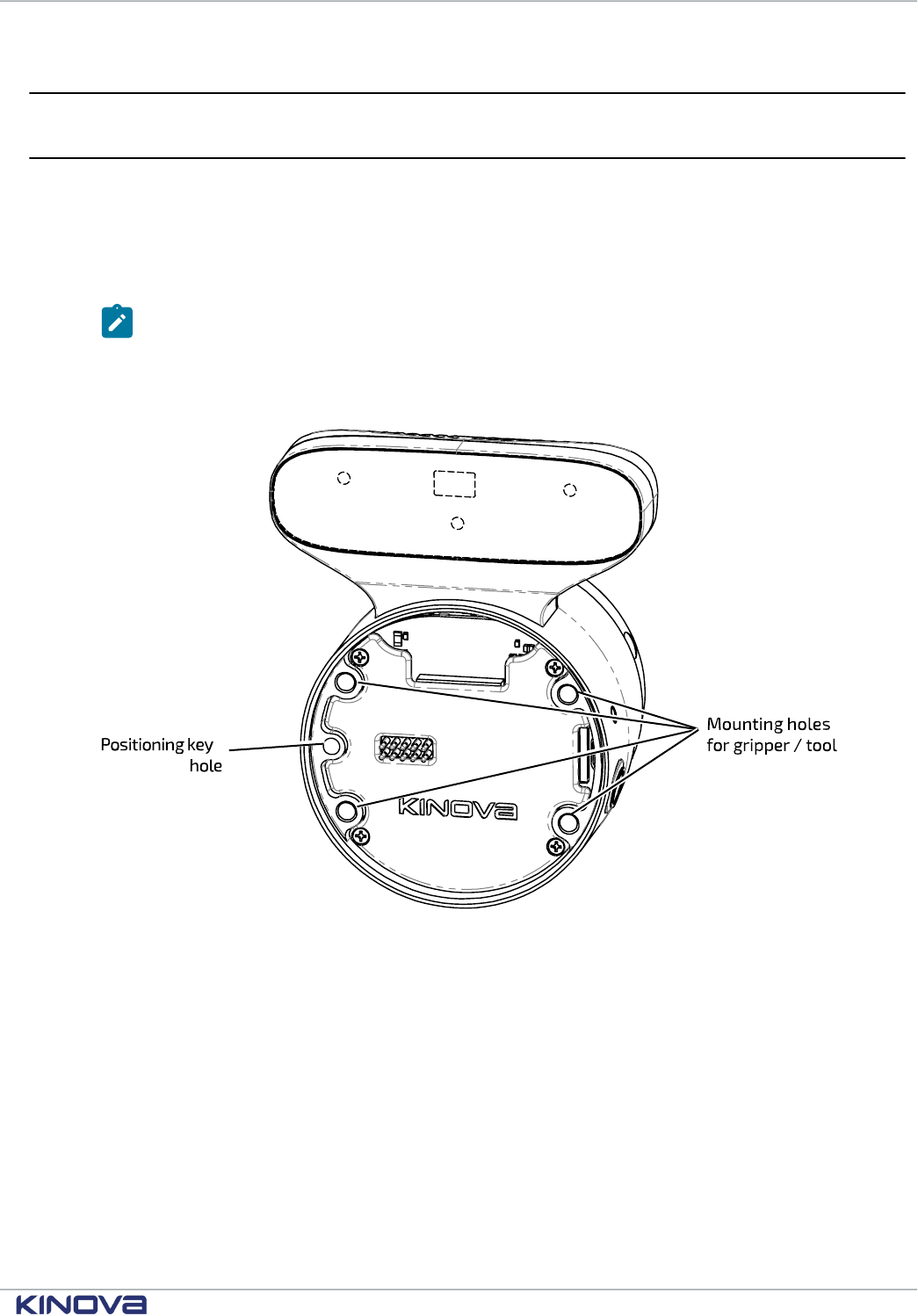
Kinova® Gen3 Ultra lightweight robot User Guide 70
Wrist interface, tool expansion, and vision
Interface module expansion - tips for installing tools
Describes steps needed to install and integrate a new tool onto the interface module.
At some point, you may want to install a new tool such as a gripper or sensor onto the robot.
Generally, this involves two steps.
1. Physically mounting the tool using the screw holes available on the Interface module face.
Note: The holes on the Interface module face are laid out to allow easy installation of
Robotiq Adaptive Grippers using the four supplied M5 Socket Head Cap Screws (SHCS
include O-rings for compliance with the IP rating for sealing). For other third-party tools,
it may be necessary to create a mounting structure matching the provided interface
module bolting pattern, as discussed in the End effector reference design section.
2. Intergrating the tool to robot power and control. Integration of Robotiq Adaptive Grippers
to the robot power and control signals uses the 10-pin spring-loaded connector. Other third-
+1 514-277-3777 kinovarobotics.com
© 2022 Kinova inc. All rights reserved.
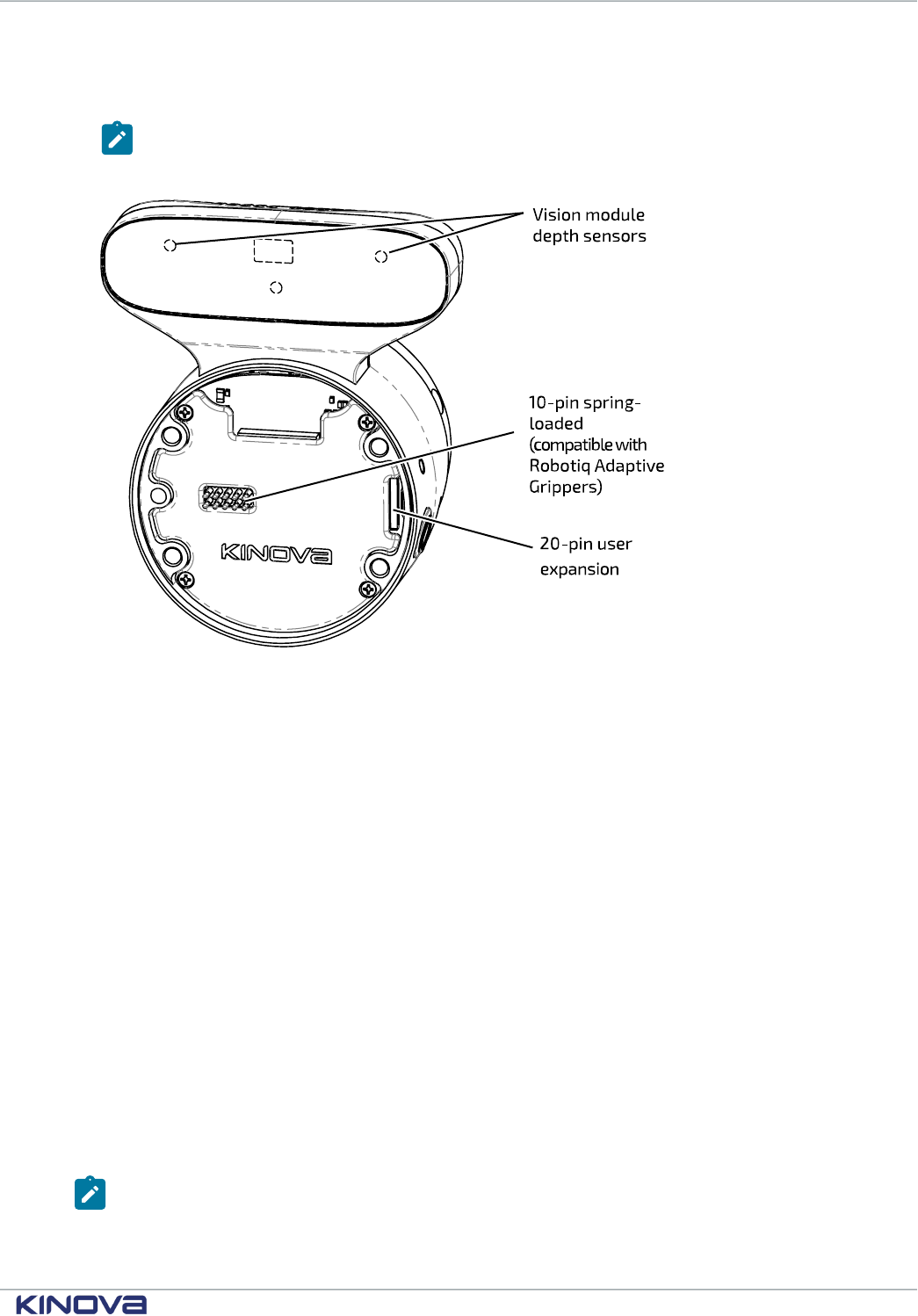
Kinova® Gen3 Ultra lightweight robot User Guide 71
party tools can be powered through the pogo pins. Power, Ethernet, UART, I2C, and GPIOs are
available via the user expansion connector. The pinout details are described in later sections.
Note: If designing or installing your own tool or end effector, remember to take into
consideration the field of view of the depth sensors when designing the length of the tool
to avoid hindering the effectiveness of the vision module depth sensors.
End eector reference design
An end effector reference design package is on the Kinova website. The package provides developers
guidance on developing and integrating a new tool with the robot. The reference design includes a mechanical
and electrical interface. Steps are required to configure the tool and its payload. Control of the tool is carried
out using the interface module expansion interface.
Introduction
The Kinova
®
Gen3 Ultra lightweight robot is designed for maximum extensibility. As such, the robot
has a user expansion interface designed to simplify the development required to incorporate
different sensors, end effectors or other tools/boards. The supported user interfaces are listed in
the section Interface module user expansion connector pinout.
Kinova provides a reference design package which includes mechanical and electrical modular
interfaces.
Mechanical interface
The mechanical interface is a flanged circular structure which converts the interface module bolting
pattern to the ISO 9409-1-A50 mounting plate pattern common to many industrial robots.
Kinova recommends that the mechanical interface part of your end effector be machined from solid
aluminium, though for applications where no payload will be attached (only sensors or PCBs), a 3D-
printed interface part may suffice.
Note: If a 3D printed interface is used, perform an evaluation of the forces involved to
ensure that adequate safety factors are observed.
+1 514-277-3777 kinovarobotics.com
© 2022 Kinova inc. All rights reserved.
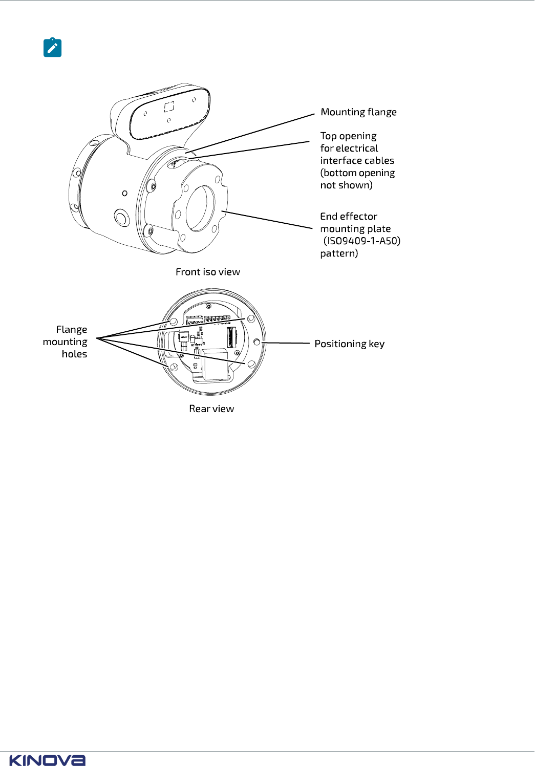
Kinova® Gen3 Ultra lightweight robot User Guide 72
Note: The structure includes openings at the top and bottom of the structure for the
passage of cabling for the electrical interface. As a result, the mounting structure does NOT
in itself provide ingress or EMI protection.
Figure 35: Reference design mechanical interface (details in reference design package)
The flange includes four mounting holes corresponding to the four mounting holes on the interface
module. The rear face of the structure also includes a positioning key corresponding to the
positioning key hole on the interface module to ensure that the structure is aligned with the right
orientation.
Electrical interface
The electrical reference design acts as a breakout, giving access to:
• 24 V / 0.5 A
• 5 V / 2 A / 10 W, from 24 V (through a DC-DC buck converter)
• Expansion Ethernet (100 Mbit, through a RJ-45 port)
•
GPIO, I
2
C and UART
+1 514-277-3777 kinovarobotics.com
© 2022 Kinova inc. All rights reserved.
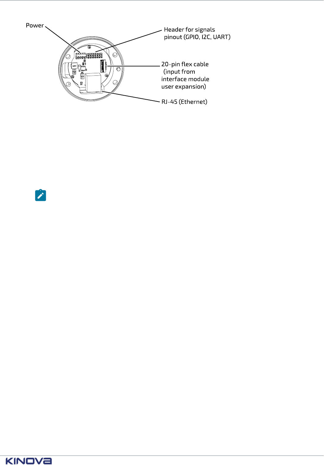
Kinova® Gen3 Ultra lightweight robot User Guide 73
Figure 36: Reference design electrical interface (details in reference design package)
Mounting structure installation overview
The following general steps are required to install the reference design mounting structure on the
robot:
• If you have not already done so, remove the end cap from the interface module, preserving the
four screws and the O-ring. The screws and O-ring are used for the installation of the mounting
structure.
• Align the rear face of the mounting structure with the interface module.
Note: Ensure that the positioning key aligns with the positioning key hole on the interface
module.
• Use a 20 pin flat flex cable to connect the user expansion port on the interface module to the
input connector on the mounting structure electrical interface.
• Place the O-ring around the mounting structure.
• Bring the mounting structure together with the interface and attach using the four screws.
With the mounting structure in place, an end effector tool can be mounted and integrated
electrically.
Reference design package
The reference design package is available for download on the Kinova website: https://
artifactory.kinovaapps.com/artifactory/generic-documentation-public/Documentation/Gen3/
CADS%20%26%20Drawings/End_Effector_Reference_Design.zip. Other resources are available
online: https://www.kinovarobotics.com/product/gen3-robots#Product__resources
The package includes several useful files to help you with building an end effector. You may use
these files as is or as a starting point to design your own end effector. The package contents include:
• STL file of the mechanical interface, for 3D-printing
• STEP file and PDF drawing of the mechanical interface, for machining
• STEP file of the Kinova breakout PCB for integration into CAD programs
• KR13933.ASY file which directs the assembly of the PCB (including the BOM)
• KR13933.PCB which directs the PCB fabrication (including Gerber files)
• KR13933.SCH which includes the circuit board schematic diagrams
Tool configuration
To fully integrate an end effector tool with the robot control and cyclic feedback, you will need to
configure the tool information using either the Web App Robot Configurations page or the
API via the SetToolConfiguration() function in Kinova.Api.ControlConfig.
You will need to configure:
+1 514-277-3777 kinovarobotics.com
© 2022 Kinova inc. All rights reserved.

Kinova® Gen3 Ultra lightweight robot User Guide 74
• transform for the reference frame of the tool in relation to robot interface module frame
• mass of mechanical interface + end effector tool
• coordinates of center of mass of mechanical interface + end effector tool in terms of the
interface module reference frame
Configuring the transform ensures that the robot is aware of the geometry of the tool in relation to
the rest of the robot to calculate and accurately report the tool position.
Configuring the mass and center of mass coordinates of the tool ensures that the control libraries
of the robot can properly take into account the presence of the tool mass in the control of the robot.
Payload configuration
If you want to carry a known payload mass with the tool, you will need to configure the payload
information using either the Web App Robot Configurations page or the API via the
SetPayloadConfiguration() function in Kinova.Api.ControlConfig.
For this you will need to configure:
• mass of the the payload
• coordinates of the center of mass of the payload in terms of the tool frame.
Similar to the configuration of tool mass and center of mass coordinates, configuring the payload
ensures that the control libraries of the robot can properly take into account the presence of the
tool mass in the control of the robot.
Controlling the end eector via interface expansion
With your end effector tool physically mounted on the mechanical interface, integrated electrically
via the electrical interface, and properly configured, you can communicate with and control the end
effector tool via the expansion interface. For more details, see Using interface module expansion to
control devices via API on page 82.
Removing end cap from the interface module
The interface module ships with an end cap to protect the interface. This needs to be removed to expose the
interface for connecting a tool.
Before you begin
You will need a 3 mm hex key.
About this task
The robot ships originally with an end cap over the interface. Attaching an end effector to the robot requires
removing the end cap first. Removing the end cap exposes expansion and end-effector connection points.
When removing the end cap, there is an O-ring exposed which must be conserved. The O-ring
is used to provide protection against water ingress and EMI at the junction between the robot
interface and the end effector.
+1 514-277-3777 kinovarobotics.com
© 2022 Kinova inc. All rights reserved.
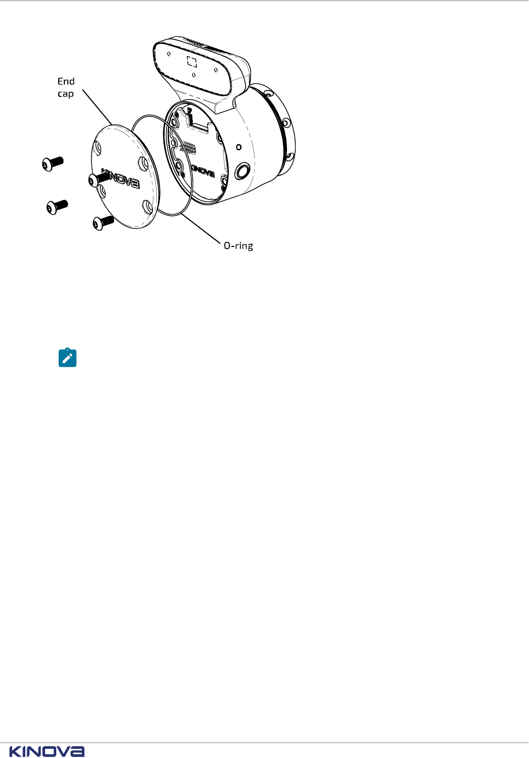
Kinova® Gen3 Ultra lightweight robot User Guide 75
Procedure
1. The end cap is held onto the robot interface using four M5 button head cap screws. Using a 3
mm hex key, remove the screws and preserve them.
2. Remove the end cap, and set aside with the screws.
3. You will see an O-ring on removing the end cap.
Note: Set aside the O-ring with the screws and end cap for safe keeping. The screws and
O-ring will be used when attaching an end effector tool (as described in the end effector
reference design). The cap needs to be replaced whenever an end effector is not installed.
Robotiq Adaptive Grippers installation (optional)
The mechanical and electrical interface of the robot makes it easy to install a Robotiq Adaptive Gripper
(2F-85 or 2F-140 gripper) on the robot. Some configuration is required.
Before you begin
You will need four M5 Socket Head Cap Screws and 4 mm hex key (supplied).
You will also need to have removed the interface end cap (robot comes with end cap connected).
You will need the O-ring that was exposed when the end cap was removed.
You will need a computer connected to the robot to perform some configuration.
About this task
This procedure describes the installation for Robotiq Adaptive Grippers on the interface module of the robot.
The interface module allows easy mounting of Robotiq Adaptive Grippers, and the Robotiq 2F-85 and 2F-140
Gripper models are fully supported on the robot and relatively simple to integrate. This procedure describes
how to:
• mechanically mount the gripper on the robot
• integrate the gripper with the robot in terms of electrical power and control
• configure the robot as using the particular gripper model in the Web App
The interface module has four mounting holes corresponding to the bolt pattern on the gripper. The 10
spring-loaded pins on the interface mate with a contact plate on the inside of the Robotiq Gripper to establish
electrical supply and controls.
+1 514-277-3777 kinovarobotics.com
© 2022 Kinova inc. All rights reserved.
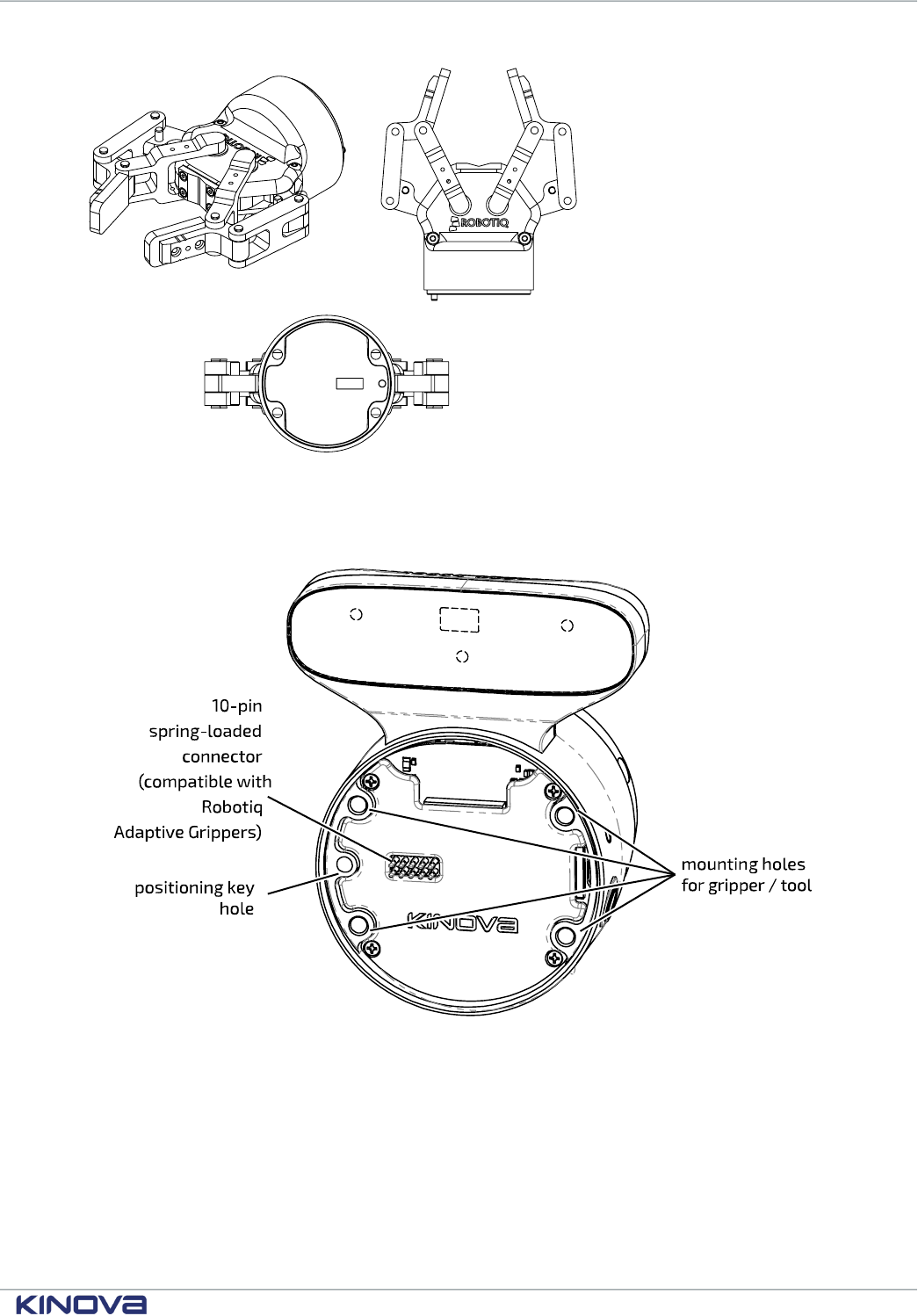
Kinova® Gen3 Ultra lightweight robot User Guide 76
Figure 37: Robotiq Adaptive Gripper (Robotiq 2F-85 Gripper shown)
Procedure
1. Prepare the four supplied M5 Socket Head Cap Screws and a 4 mm hex key.
2. Place the O-ring around the diameter of the gripper. The O-ring protects the junction between
the interface module and gripper from water ingress and EMI.
+1 514-277-3777 kinovarobotics.com
© 2022 Kinova inc. All rights reserved.
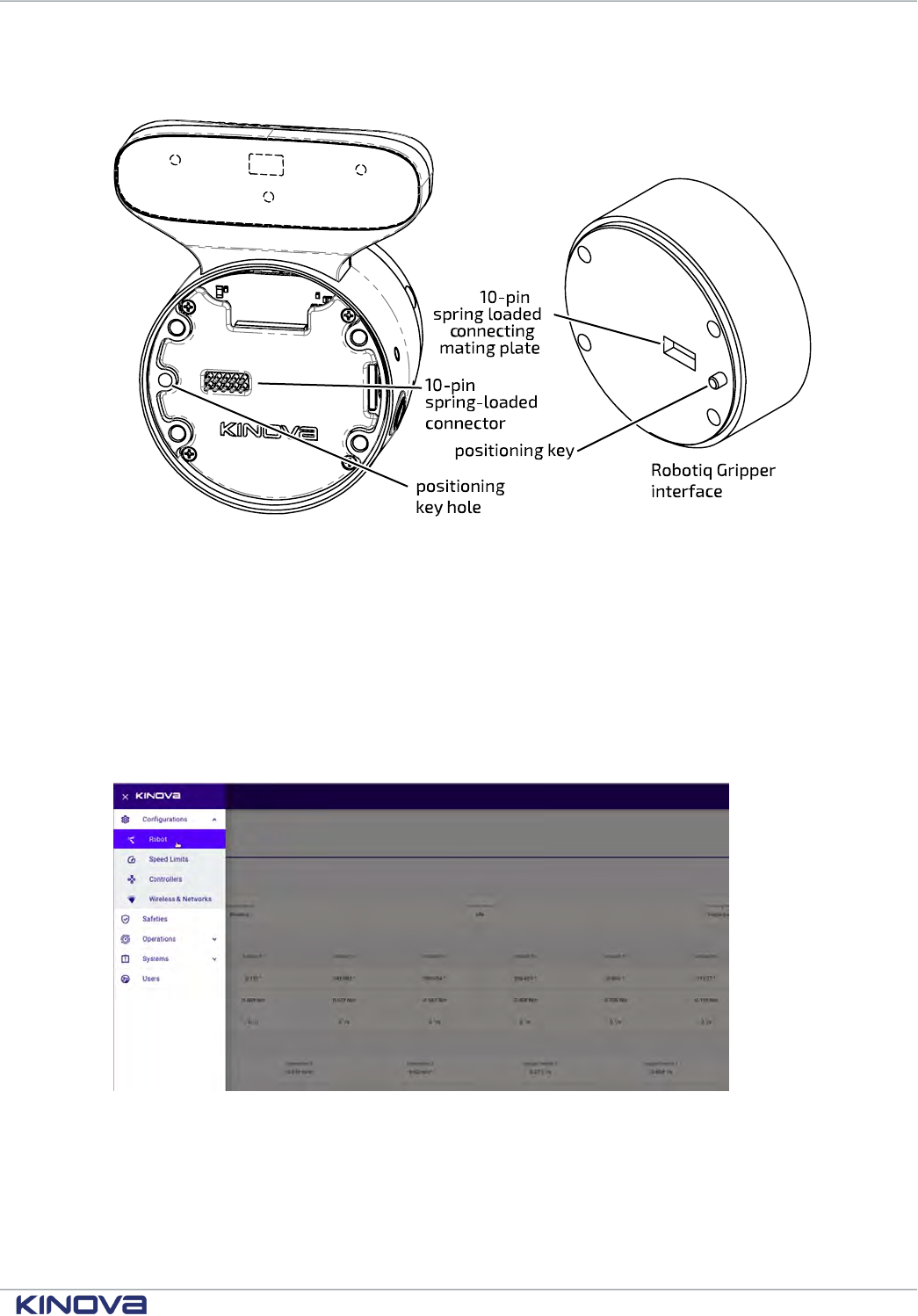
Kinova® Gen3 Ultra lightweight robot User Guide 77
3. Locate the positioning key on the Robotiq Gripper and the corresponding hole on the interface
module face.
4. Position the gripper interface against the Interface module interface so that the positioning
key of the gripper is in the positioning key hole of the interface module and the 10-pin spring-
loaded connector of the interface module is aligned with the corresponding mating interface
on the gripper.
5. Insert the four screws through the front face of the gripper. Tighten each screw in sequence
until they are all snug (do not overtighten).
6. Next, some configuration is required to integrate the gripper at the software level. You need to
tell the robot what gripper model is connected. With the robot connected to a computer, open
the Web App and log in.
7. In the menu, access the Robot configuration page from the Configurations page group.
8. On the Robot configurations page, open the Arm configurations tab and the Product
section. There is a field End Effector Type, with a dropdown menu selector. You will see two
+1 514-277-3777 kinovarobotics.com
© 2022 Kinova inc. All rights reserved.
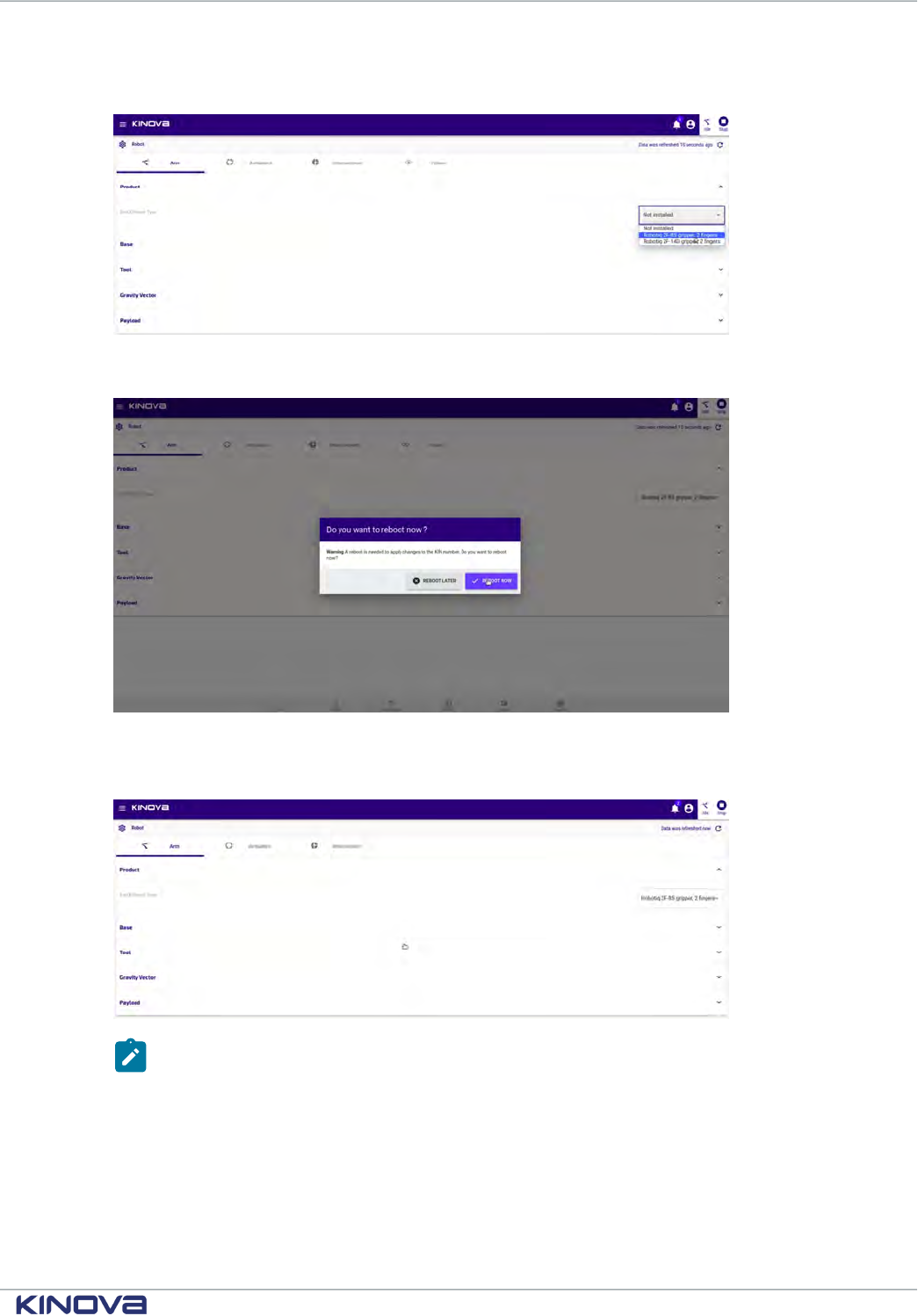
Kinova® Gen3 Ultra lightweight robot User Guide 78
options: Robotiq 2F-85 gripper, 2 fingers and Robotiq 2F-140 gripper, 2
fingers. Choose your gripper type from the list.
9. Once you select the gripper type, you will be prompted to reboot the robot to apply the
changes to the configuration.
10. The robot will go through a reboot, and the Web App will refresh, waiting for the reboot to
finish. When the process is done (about 30 seconds), the End Effector Type will appear on the
Robot configurations page.
Note: You can change the transform of the tool to move the default TCP set for the
gripper.
Results
The Robotiq Gripper is now be mechanically installed on the robot. The gripper is also fully integrated with
the robot for power and controls, and the gripper type is set in the software configuration of the robot. The
robot provides power to the gripper, and the gripper can be controlled using either the provided gamepad
or the Web App virtual joysticks. The robot control library will now take into account the mass and center of
mass of the gripper in controlling the robot. As well, the robot will take into account the gripper reference
frame (between the two fingers) when reporting back updates for the tool position.
+1 514-277-3777 kinovarobotics.com
© 2022 Kinova inc. All rights reserved.
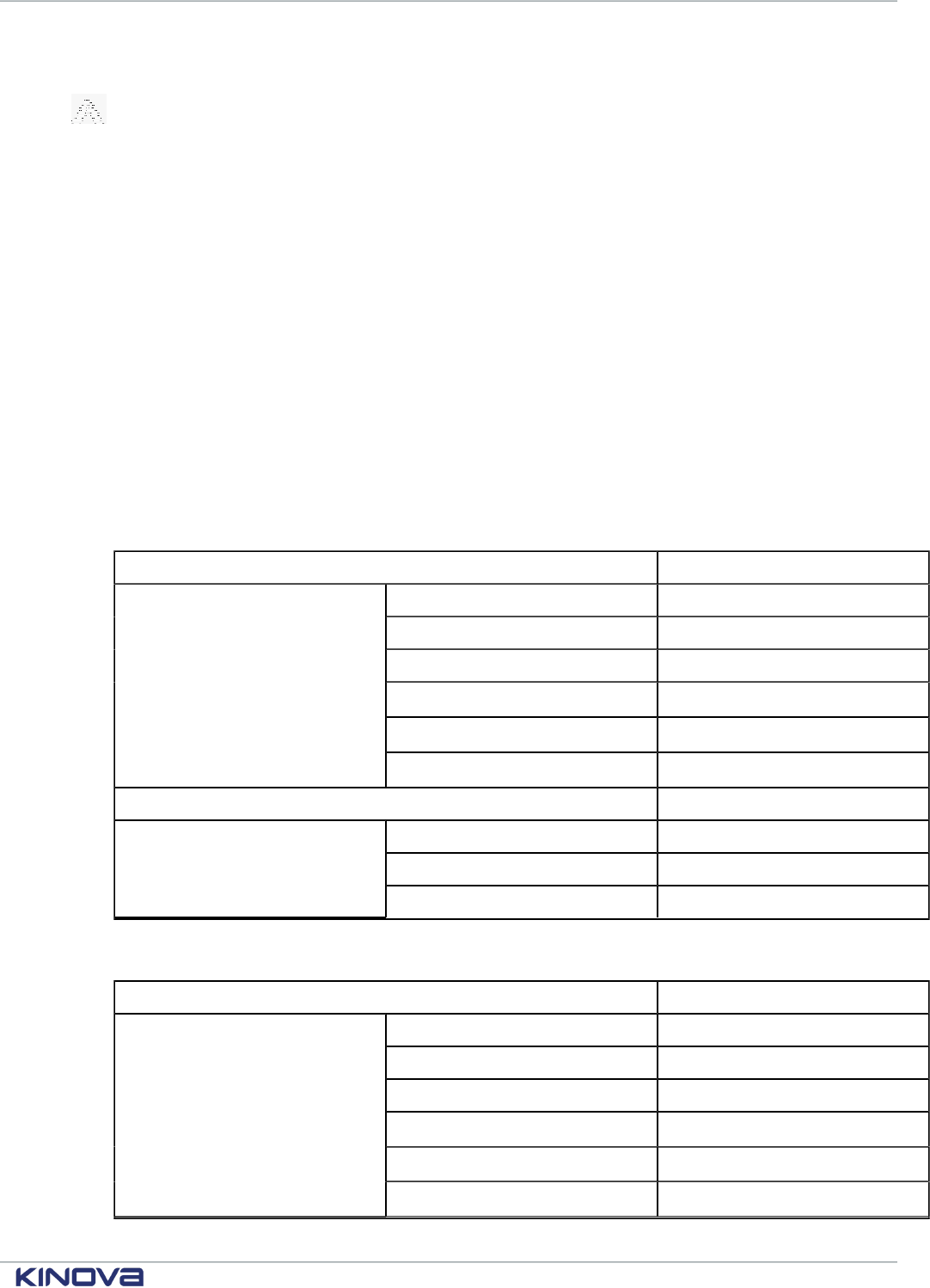
Kinova® Gen3 Ultra lightweight robot User Guide 79
What to do next
For your personal safety, it is strongly recommended that you read the user documentation for the
Robotiq Gripper before use.
Robotiq 2F-85 and 2F-140 Gripper default configuration settings reference
Reference for tool configuration settings to use for the Robotiq 2F-85 and 2F-140 Grippers. This information
is provided as a reference for advanced users and is not needed for general setup and use of the Robotiq
gripper with the robot.
The following information represents the tool configuration settings used by the robot for the
Robotiq 2F-85 and 2F-140 gripper. The gripper is fully supported on the robot, therefore there
is no need to explicitly enter the details in the tool configuration section of the Web App Robot
Configuration page or via the Kinova.Api.ControlConfig API as you would have to do
when adding another tool.
Selecting the gripper model under Arm > Product > End Effector Type on the Robot
Configuration page of the Web App and rebooting the robot suffices to apply these settings.
The information below is provided as a reference for advanced users who need to account for the
information in computing dynamics and kinematics of the robot + gripper.
Table 29: Robotiq 2F-85 Gripper tool configuration settings
Setting Value
X 0
Y 0
Z 0.120 m
θ
X
0
θ
Y
0
Transform (from interface
module frame to gripper frame)
θ
Z
0
Tool mass 0.925 kg
X 0
Y 0
Center of mass coordinates
(in interface module frame)
Z 0.058 m
Table 30: Robotiq 2F-140 Gripper tool configuration settings
Setting Value
X 0
Y 0
Z 0.200 m
θ
X
0
θ
Y
0
Transform (from interface
module frame to gripper frame)
θ
Z
0
+1 514-277-3777 kinovarobotics.com
© 2022 Kinova inc. All rights reserved.
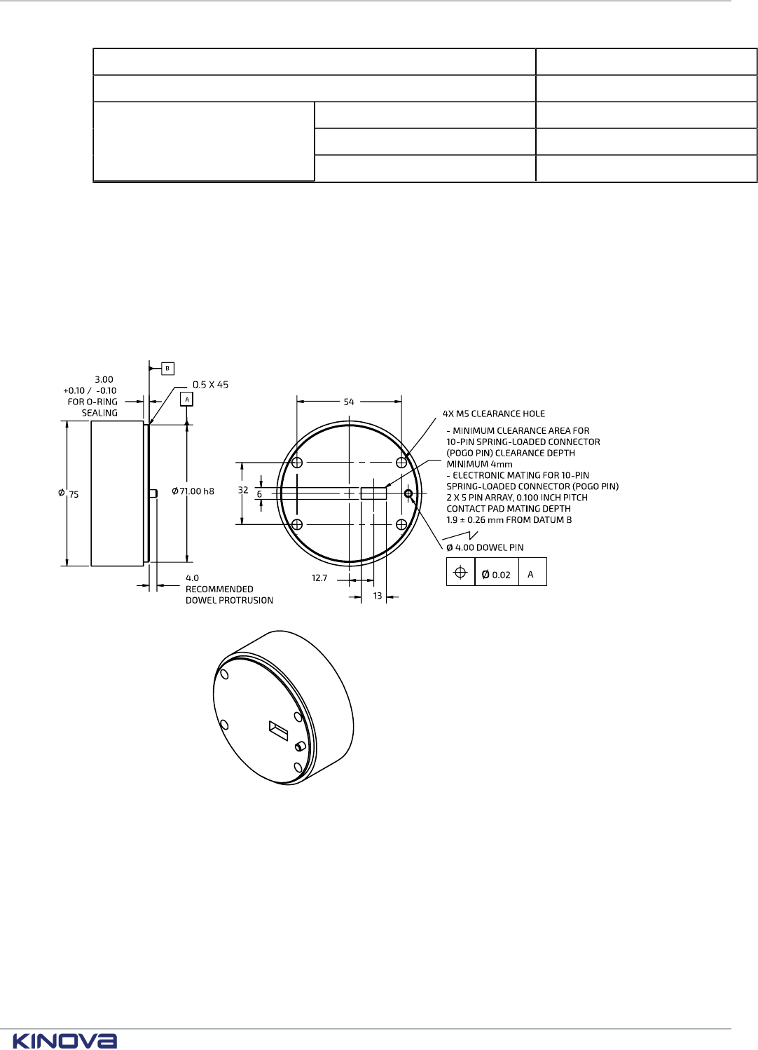
Kinova® Gen3 Ultra lightweight robot User Guide 80
Setting Value
Tool mass 1.025 kg
X 0
Y 0
Center of mass coordinates
(in interface module frame)
Z 0.073 m
Interface module bolting pattern
Reference for the interface module bolting pattern (mechanical interface). This is useful for mounting a tool
on the robot.
Drill pattern for mounting screws and position key
The drill pattern below is for the four mounting screws. Openings to accommodate the required
cables connections with the connectors also need to be added. The use of a 4 mm dowel pin to
accurately localize the positioning key hole is optional but strongly recommended.
Figure 38: Mounting holes for gripper/tool (all dimensions in mm)
Interface module user expansion connector pinout
Pinout reference for the interface module user expansion connector.
The interface module user expansion connector pin assignment is described in the table below.
These expansion pins provide power to devices connected at the interface module, as well as
offering connectivity to enable control of devices via the APIs.
+1 514-277-3777 kinovarobotics.com
© 2022 Kinova inc. All rights reserved.
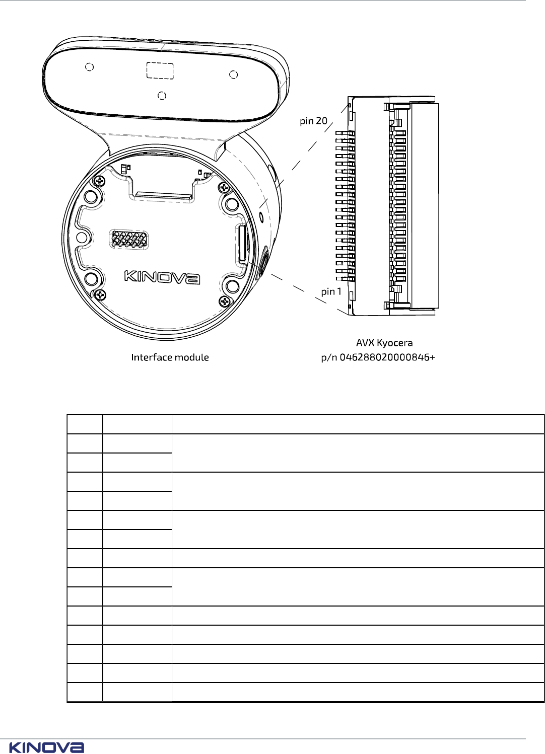
Kinova® Gen3 Ultra lightweight robot User Guide 81
Figure 39: Interface module user expansion connector
Table 31: Interface module user expansion pinout
Pin Name Comment
1 +24V USER
2 +24V USER
24V / 0.5A power; a protection device limits current shared between gripper and
user expansion port to 1A total.
3 GND
4 GND
power return path
5 ETH_RX_P
6 ETH_RX_N
Ethernet Rx 100Mbps (connected with EXP bus)
7 GND signal return path
8 ETH_TX_P
9 ETH_TX_N
Ethernet Tx 100Mbps (connected with EXP bus)
10 GND signal return path
11 +3V3 3.3V / 100 mA; can be used for small IC or sensor
12 UART_TXD signal 3.3V
13 UART_RXD signal 3.3V
14 GND signal return path
+1 514-277-3777 kinovarobotics.com
© 2022 Kinova inc. All rights reserved.
Kinova® Gen3 Ultra lightweight robot User Guide 82
Pin Name Comment
15 I2C_SCL
I
2
C clock - 3.3V
16 I2C_SDA
I
2
C data - 3.3V
17 GPIO1
18 GPIO2
19 GPIO3
20 GPIO4
General Purpose Input / Output 3.3V
Using interface module expansion to control devices via API
References for additional information on how to make use of interface module expansion pins for bridging to
connected devices via UART, I2C, or GPIO.
Overview
The interface module expansion connector offers three interfaces for bridging to connected
devices:
• UART
• I2C
• GPIO
The reference design section gives guidance on connecting an end effector device mechanically and
electrically.
Controlling the end eector device via UART, I2C, or GPIO
Controlling the interfaced device via UART, I2C, or GPIO is done via the Kinova
®
Kortex™ API using
the Kinova.Api.InterconnectConfig service.
Examples of using UART, I2C, and GPIO as a bridge to communciate with and control a device can
be seen on the Kiniova
®
Kortex™ GitHub repository.
• C++ examples
• Python examples
Spring-loaded connector pinout
Pinout reference for the spring-loaded connector.
The spring-loaded connector pin assignment is described in the table below.
+1 514-277-3777 kinovarobotics.com
© 2022 Kinova inc. All rights reserved.
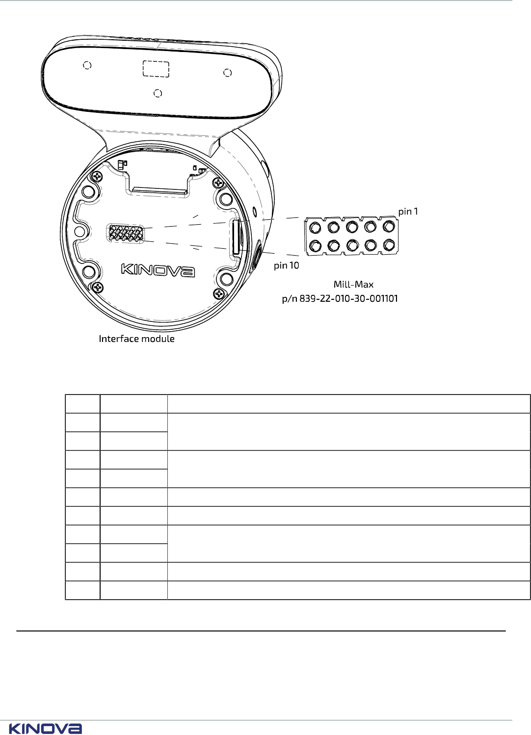
Kinova® Gen3 Ultra lightweight robot User Guide 83
Figure 40: Spring-loaded connector
Table 32: Spring-loaded connector pinout
Pin Name Comment
1 GND
2 GND
power return path
3 +24V
4 +24V
24V / 1A power for end device (current limit shared with interface module user
expansion port)
5 PRESENT end device presence detection (connect to GND on end device)
6 N/C no connection
7 RS485_N
8 RS485_P
RS-485 signal pair (bidirectional; Robotiq devices only)
9 GND signal return path
10 N/C no connection
Accessing Vision module color and depth streams
The vision module color and depth streams can be accessed from a computer connected to the robot base.
The video module sensors capture two video streams:
• color
+1 514-277-3777 kinovarobotics.com
© 2022 Kinova inc. All rights reserved.

Kinova® Gen3 Ultra lightweight robot User Guide 84
• depth
The data from these streams is sent from the vision module back to the base controller via the
vision / expansion channel carried over the internal flex cable links.
These two streams are accessible via the Real Time Streaming Protocol (RTSP) on a computer
connected to the robot (with transport over real-time transport protocol (RTP)).
Using the default IP address settings for the base controller, the two streams are accessible via:
• color sensor stream: rtsp://<base IPv4 address>/color
• depth sensor stream: rtsp://<base IPv4 address>/depth
For the default configuration of the base controller network interface, this would give:
• rtsp://192.168.1.10/color
• rtsp://192.168.1.10/depth
Note: Examples in the documentation will use the default base controller IP setting for
simplicity.
Streams specifications
• pixel format: Z16 pixel format - 16 bits LSB transferred as grayscale
• H.264 baseline profile (constant bitrate)
• RTSP server listening on port 554 (default)
• maximum of two simultaneous connections per stream
• inactivity timeout of 30 seconds
The Kinova
®
Kortex™ Developer Guide section of the user guide describes in more detail how to
work with the vision module camera streams.
For more guidance on configuring the vision module using the Kinova
®
Kortex™ API, see the vision
examples on the Kinova
®
Kortex™ GitHub repository:
• C++ vision examples
• Python vision examples
+1 514-277-3777 kinovarobotics.com
© 2022 Kinova inc. All rights reserved.

Kinova® Gen3 Ultra lightweight robot User Guide 85
Concepts and terminology
Robot key concepts and terminology
Actions
An action is something that the user wants the robot to do. This can include (but is not limited to):
• Reaching an end effector pose or set of joint angles
• Reaching or passing through or near a waypoint
• Toggling admittance mode
• Changing a position or motion parameter
• Applying emergency stop or clear faults
• Adding a delay
• Sending a gripper command
The full set of action types is defined in the Kinova.Api.Base API.
Admittance
In this document, admittance is used to refer to human-robot interaction modes. In these modes, the robot
will respond to external efforts applied on the body and tool and generate a motion to follow these efforts.
Angular mode
Independent joint control, whereby each axis of the manipulator is controlled separately.
Axis
A fixed line with direction. It is used for the measurement of coordinates or angles, in relation to which is
specified the robot motion (in linear or rotational fashion).
Base
Refers to the stationary base structure of a robot arm that supports the first arm joint.
Base frame
The reference frame located at the center of the bottom surface of the arm's base. This serves as the origin
frame in Cartesian space.
Base support
The stable platform to which the base is attached
Blending
Blending is the process used by the robot to smooth the transition when reaching a waypoint that creates a
change in direction in a trajectory. Blending at a waypoint is defined by a blending radius that dictate at which
distance from the associated waypoint does the trajectory start transitioning to the next one.
Cartesian admittance mode
Allows the application of external force to the tool, so as to guide the arm to a new position.
Cartesian mode
Mode used to control the velocities (translation and orientation) of the tool in Cartesian space.
+1 514-277-3777 kinovarobotics.com
© 2022 Kinova inc. All rights reserved.

Kinova® Gen3 Ultra lightweight robot User Guide 86
Cartesian space
The Euclidean space described by x, y and z axes of the Cartesian coordinate system.
Center of mass
Unique point of a rigid body where an applied force will generate only linear acceleration (and no angular
acceleration)
Closed loop control
Control of a device where the device is controlled in relation to the different between sensed current state
and goal state. Used on the robot for control of actuators.
Control modes
A control mode is one of several modalities of controlling the motion of the robot while it is in
run mode. Different modes provide different means to describe or guide the desired motion. The
control modes for the arm are:
• Angular joystick
• Angular trajectory
• Angular waypoint trajectories
• Cartesian joystick
• Cartesian trajectory
• Cartesian waypoing trajectories
• Cartesian admittance
• Joint admittance
• Null space admittance
• Force control
Coordinate system
A system used to represent a position in three-dimensional space, consisting of three coordinate axes and an
origin. The term "frame" is also used to designate a coordinate system.
Degrees of Freedom (DoF)
The number of independent directions or joints of the robot, which would allow the robot to move its end
effector through the required sequence of motions. For arbitrary positioning, six degrees of freedom are
needed: three for position and three for orientation.
Endpoint
The nominal commanded position that the robot will try to reach with the tool center point at the end of a
motion path.
End eector
The device at the end of a robot, designed to directly interact with the environment. When nothing is
attached to the arm, the end effector is the flange; when a tool is attached to the arm, the end effector is the
tool.
Euler angle
Describes the rotation in three dimensions of a rigid body in terms of a sequence of three rotations with
respect to a coordinate system.
+1 514-277-3777 kinovarobotics.com
© 2022 Kinova inc. All rights reserved.

Kinova® Gen3 Ultra lightweight robot User Guide 87
Factory settings
Factory settings are the configuration settings of the robot as they were when the robot arrived
from the manufacturer. A robot can be restored to factory settings, which includes the base
configuration and the network settings.
Force control
The tool is controlled by sending wrench commands (force and torque) to the tool.
Gravity vector
Vector representing direction and magnitude of the local force of gravity, expressed in terms of the robot
base frame.
Joint
Section of the manipulator system which allows one rotational degree of freedom.
Joint admittance mode
Allows the application of external force at the links to rotate joints.
Joint angle
Describes the position of every joint of a robot as as series of angles.
Joint space
The set of all possible joint positions.
Map
A map is a set of associations between controller device inputs and actions to be triggered by those
inputs when the map is active.
Mappings
A mapping is a full definition of the possible correspondances between controller device inputs
and actions that are triggered by those inputs when the mapping is active. A mapping can consist of
multiple maps, for example to enable multiple different modes on the same controller device.
Notifications
A notification is a log of an event related to a particular topic that happens while a user is using the
robot.
A notification will include the user profile, type of event, details of the event (if applicable), and a
timestamp.
Null space
The mathematical space of joint speeds where the robot can change its configuration (generate joint speed
and motion) without changing the end-effector pose (Null Twist at the end effector).
Null space admittance mode
Robot configuration can be changed by applying external forces at the links without affecting the tool pose.
+1 514-277-3777 kinovarobotics.com
© 2022 Kinova inc. All rights reserved.

Kinova® Gen3 Ultra lightweight robot User Guide 88
Operating mode
Operating modes are the different operational states of the robot. The operating modes for the arm
are:
• Update - in process of update
• Update completed - update is completed successfully
• Update failed - update process started but failed to complete successfully
• Shutting down - arm is in process of shutting down
• Run - normal operating mode. Arm is ready to accept control inputs.
• Fault - robot is in an error state
Orientation
The orientation of a rigid body describes the pure rotations that should be applied to the body to move it from
a reference placement to its current placement.
Path
The continuous locus of points (or positions in three dimensional space) traversed by the tool center point
and described in a specified coordinate system.
Path (Angular)
The set of at least two angular poses, through which the actuator values angles should pass during motion.
Path (Cartesian)
The set of at least two Cartesian poses, through which the tool of the robot should pass during motion.
Path planning
Computation of a path to reach a goal pose subject to applicable constraints and criteria.
Payload
The object that is carried or manipulated by the robot tool.
Payload - Maximum
The maximum mass that the robot can manipulate at a specified speed, acceleration/deceleration, center of
gravity location (offset), and repeatability in continuous operation over a specified working space, specified in
kilograms.
Pinch point
Any location on the robot (or its accessories) which poses a risk of injury to fingers or other appendages close
by.
Pose
Describes the position and orientation of a rigid body in Cartesian space.
Position
The definition of an object's location in 3D space, usually defined by a 3D coordinate system using X, Y, and Z
coordinates.
+1 514-277-3777 kinovarobotics.com
© 2022 Kinova inc. All rights reserved.

Kinova® Gen3 Ultra lightweight robot User Guide 89
Protection zone
A protection zone defines a three-dimensional region with respect to the robot base where the end
effector or the arm is prevented from entering. The speed at which the end effector and arm travel
as it approaches a protection zone is dictated by the protection zone. Protection zones are used for
preventing collisions. For the robot, protection zones can be one of three shapes (or combination
thereof):
• Cylinder
• Rectangular prism
• Sphere
Redundancy
Occurs when a manipulator (robot) has more degrees of freedom than it needs to execute a given task.
Applicable to robots with 7 or more DoF.
Redundancy Optimization
Method used to avoid a singularity by using redundant degrees-of-freedom motion (if available).
Safeties
Hardware limitations which are monitored to increase robot safety.
Sequence
A sequence is an ordered list of actions executed one after the other. A sequence can be started,
paused, resumed, and stopped.
Servoing mode
A servoing mode is a modality through which commands are transmitted to robot devices during
operation. The servoing modes are as follows:
• High-level servoing - user(s) control the robot by sending a single command to the base. The
base manages the low-level details of executing the command, breaking it down, applying
any relevant high-level protections, and routing commands to the desired devices via a 1 kHz
communication loop with the devices.
º Single-level - a single user sends commands to a base
• Low-level servoing - the user controls the robot by sending a series of actuator commands to the
base via a user-controlled loop. The base routes these commands to the desired device via its
own 1 kHz communication loop with the actuators.
Singularity avoidance
Strategy to avoid configurations where the robot loses its ability to move the end effector in a given direction
no matter how it moves its joints.
Snapshot
A snapshot is a capture of the instantaneous position of the robot. This can be of different types:
• Cartesian position
• Joint angles
• gripper position
+1 514-277-3777 kinovarobotics.com
© 2022 Kinova inc. All rights reserved.

Kinova® Gen3 Ultra lightweight robot User Guide 90
• Combined robot position and gripper position
Teaching mode
Teaching mode is a feature available via the Kinova
®
Kortex™ Web App. Teaching mode allows users to put
the robot into admittance, move the robot by hand, and capture position and gripper snapshots within a
sequence.
Tool
The device attached to the end of a robot, designed to directly interact with the environment.
Tool configuration
Configurations made to enable use of a tool at the end effector position of the robot. This consists of the mass
and center of mass of the tool, and the tool transform.
Tool frame
A coordinate system attached to the end effector tool.
Tool transform
Transformation (translation and orientation) between the interface module reference frame and the
reference frame of the tool attached to the end of the robot.
Topic
A set of related robot events to which the user can subscribe and receive notifications as part of a
Publisher-Subscriber (pub-sub) arrangement. There are a number of different topics, including:
• User
• Controller device input
• Safety
• Action or sequence
• Connection/disconnection of arm, controller, or tool
• Configuration change or backup
• Factory restore
• Protection zone
• Control, operation, or servoing mode
For a full list of events, refer to https://github.com/Kinovarobotics/kortex/blob/master/linked_md/
NotificationTopics.md
Torque control
The motion of the robot joints is controlled by sending low-level torque commands to the actuators.
Trajectory
A time-parametrized path in the robot workspace that can be defined by the user.
Trajectory mode
Mode allowing user to specify an endpoint (in joint space or Cartesian space) that the robot should reach.
+1 514-277-3777 kinovarobotics.com
© 2022 Kinova inc. All rights reserved.

Kinova® Gen3 Ultra lightweight robot User Guide 91
Twist
Generalized velocity vector, which is a combination of translational velocity and rotational velocity. Term
comes from Screw Theory.
Upgrade package
An upgrade package is a file with the extension .swu. It contains firmware updates for all modules
on the robot (base, actuator, interface, vision).
User profiles
A user profile is a collection of basic information about the person using the robot, along with
credentials (username and password) for access. A user profile allows access to the robot to be
controlled based on login credentials, and allows permissions for reading, updating, and deleting
different configuration items to be controlled. The user profile also allows notifications for events
happening during a user's session to be associated with the user. Notifications that were sent by
the robot can be viewed in the Web App > Notifications page if the Web App is open and
connected to the robot before the notifications were sent.
Vector
Mathematical representation of physical quantities that have both magnitude and direction, expressed in a
coordinate system.
Waypoint
A waypoint is a desired intermediate point to be reached during a robot movement, either a Cartesian pose
or a set of joint angles. A list of waypoints can be created to make a trajectory that changes direction without
reducing velocities to zero by smoothing changes in direction.
Wrench
Generalized force vector, which is a combination of linear force and torques. Term comes from Screw Theory.
+1 514-277-3777 kinovarobotics.com
© 2022 Kinova inc. All rights reserved.

Kinova® Gen3 Ultra lightweight robot User Guide 92
Robot control
High-level and low-level robot control
The robot can be controlled in either high-level or low-level robot control. There are benefits to both forms
of control. High-level control is easier with more protections, while low-level control offers faster commands
and finer-grained control with less protection.
High-level is the default on boot-up and offers the safest and most straight-forward control.
In both high-level and low-level, commands are sent through the robot base.
In high-level control, commands are sent to the base via a single command using the
Kinova.Api.Base API. These commands are processed by Kinova robot control libraries.
The robot control library applies high-level control features like:
• Singularity avoidance
• Protection zones
• Cartesian and joint limits
• Configurable speed and acceleration limits
The control library also breaks down the command into smaller commands that the base will
send incrementally to the individual robot actuators via its 1 kHz communication loop with the
actuators.
In low-level control, the user sends a series of small commands to each actuator and the gripper as
part of a user-defined loop, at a rate up to 1 kHz, using the Kinova.Api.BaseCyclic API. The
base receives these commands and routes them to the appropriate actuators and the gripper via its
own 1 KHz communication loop with robot devices.
High-level control is simpler to use and offers added protections. However, it is slower due to the
overhead of processing by the Kinova control library. High-level control runs at 40 Hz.
Low-level control offers faster commands and finer-grained control of the robot. The user's
commands can be applied directly to the actuators without being changed by the high-level control
features, which is useful, for example, when implementing a controller external to the robot. The
user should be aware that the protection offered by the high-level control libraries will not be
applied as a result.
For detailed information on the implementation of high- and low-level control, see Robot servoing
modes on page 181 in the Kinova
®
Kortex™ Developer Guide section of this User Guide.
High-level and low-level robot control methods reference
Control robot movement by using key methods in the API. For the full API documentation and code examples,
please see the KORTEX GitHub repository or watch our videos on https://www.youtube.com/watch?
v=zQewb08M4sA&list=PLz1XwEYRuku5rZjJWBr6SDi93jgWZ4FHL
+1 514-277-3777 kinovarobotics.com
© 2022 Kinova inc. All rights reserved.
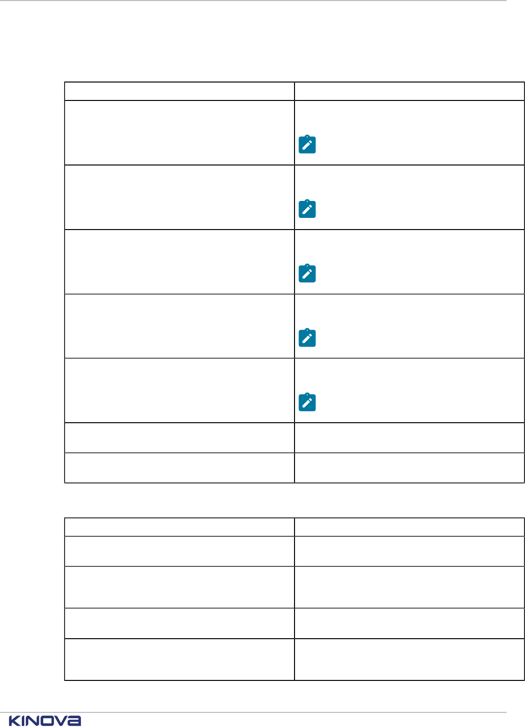
Kinova® Gen3 Ultra lightweight robot User Guide 93
High-level (Kinova.Api.Base)
Table 33: Send or play a trajectory (Cartesian or joint)
Method Description
PlayCartesianTrajectory
(ConstrainedPose)
Moves to the specifed pose (with specified Cartesian
constraint on trajectory)
Note: This method will be deprecated in
a future software version.
PlayCartesianTrajectoryPosition
(ConstrainedPosition)
Moves to the specifed position (with specified
Cartesian constraint on trajectory)
Note: This method will be deprecated in
a future software version.
PlayCartesianTrajectoryOrientation
(ConstrainedOrientation)
Moves to the specifed orientation (with specified
Cartesian constraint on trajectory)
Note: This method will be deprecated in
a future software version.
PlayJointTrajectory
(ConstrainedJointAngles)
Moves to the specified joint angles (with specified
joint constraint on trajectory)
Note: This method will be deprecated in
a future software version.
PlaySelectedJointTrajectory
(ConstrainedJointAngle)
Moves specifed joint to the specifed joint angle (with
specified joint constraint on trajectory).
Note: This method will be deprecated in
a future software version.
PlayPreComputedJointTrajectory
(PreComputedJointTrajectory)
Play pre-computed angular trajectory
ExecuteWaypointTrajectory(WaypointList) Executes a trajectory defiend by a series of
waypoints in joint space or in Cartesian space
Table 34: Send Cartesian command to tool
Method Description
SendTwistCommand (TwistCommand) Sends a twist command to tool (velocity and angular
velocity)
SendTwistJoystickCommand
(TwistCommand)
Sends a twist joystick command to tool. The twist
values sent to this call are expected to be a ratio of
maximum value (between -1.0/+1.0)
(EXPERIMENTAL) SendWrenchCommand
(WrenchCommand)
Force control. Sends a wrench command to tool
(force and torque)
(EXPERIMENTAL)
SendWrenchJoystickCommand
(WrenchCommand)
Force control. Sends a wrench joystick command to
tool. The wrench values sent to this call are expected
to be a ratio of maximum value (between -1.0/+1.0)
+1 514-277-3777 kinovarobotics.com
© 2022 Kinova inc. All rights reserved.
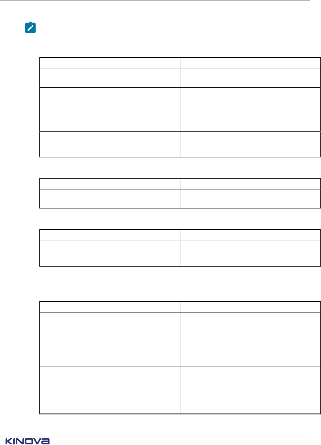
Kinova® Gen3 Ultra lightweight robot User Guide 94
Note: High-level force control is supported, but as an experimental feature only. Users
should exercise caution.
Table 35: Send command to joints
Method Description
SendJointSpeedsCommand (JointSpeeds) Sends a joint speeds command, that is the desired
speed of one or many joints
SendSelectedJointSpeedCommand
(JointSpeed)
Sends a speed command for a specific joint
SendJointSpeedsJoystickCommand
(JointSpeeds)
Sends the desired joystick speeds for one or multiple
joints. Values sent to this call are expected to be a
ratio of maximum value (between -1.0/+1.0)
SendSelectedJointSpeedJoystickCommand
(JointSpeed)
Sends a joystick speed for a specific joint. Value sent
to this call is expected to be a ratio of maximum value
(between -1.0/+1.0)
Table 36: Initiate admittance control
Method Description
SetAdmittance (Admittance) Sets the robot in the chosen admittance mode
(Cartesian, joint, null space)
Table 37: Send gripper commands
Method Description
SendGripperCommand (GripperCommand) Sends a command to move the gripper. Commands
the fingers of the gripper in either position or
velocity.
Low-level (Kinova.Api.BaseCyclic)
Table 38: Low-level cyclic commands
Method Description
Refresh (Command) Send a new incremental refresh command to the
actuators and gripper for the current 1 ms interval.
Command actuators position, angular velocity,
torque (ADVANCED USERS ONLY), and motor
current, as well as gripper finger motors. Receive
feedback on current status of base, actuators, tool,
and gripper.
RefreshCommand (Command) Send a new incremental refresh command to
the actuators and gripper for the current 1 ms
interval. Command actuators position, angular
velocity, torque (ADVANCED USERS ONLY), and
motor current, as well as gripper finger motors. No
feedback provided.
+1 514-277-3777 kinovarobotics.com
© 2022 Kinova inc. All rights reserved.
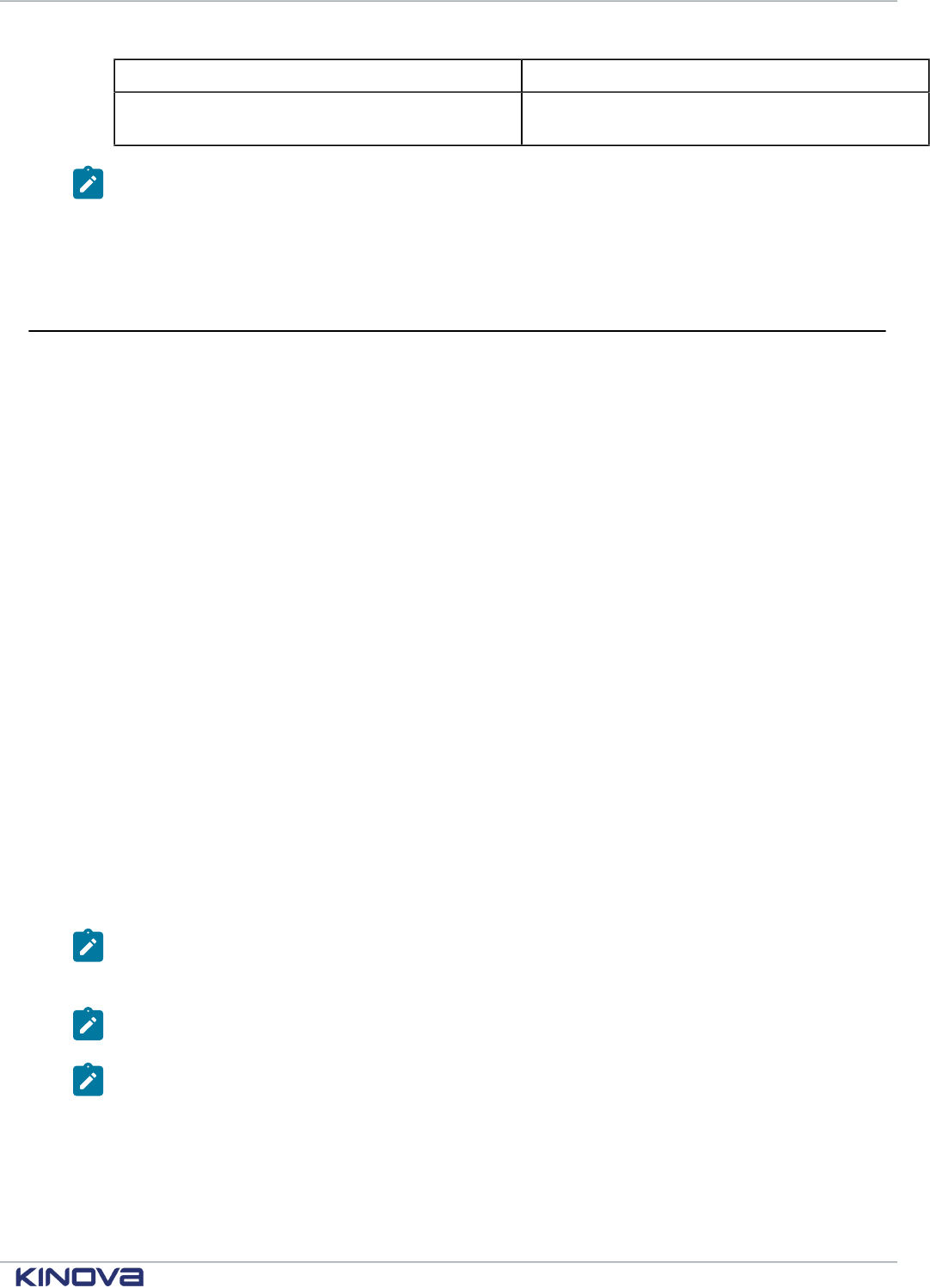
Kinova® Gen3 Ultra lightweight robot User Guide 95
Method Description
RefreshFeedback () Receive feedback on current status of base,
actuators, tool, and gripper.
Note: Low-level actuator torque control is for advanced users only and should only be
used by users who know what they are doing. It is very important to carefully monitor the
torque commands sent to the actuators to ensure that excessive torque values are not sent.
Incorrect use can lead to rapid movements that can be dangerous for people and equipment.
Make sure that the area around the robot is clear before experimenting with torque control.
Control features
Overview of control features of the robot.
The robot has the following control features that improve the safety and usability of the robot, and
protect it from damage:
• Singularity avoidance
• Protection zones
• Angular limits
• Cartesian limits
• Configurable kinematic limits
Singularity avoidance
The singularity avoidance feature of the robot control library handles or avoids singularities in Cartesian
control modes. The robot behavior, including tool speed may be altered near a singularity.
A singularity refers to any robot configuration (set of joint angles) that causes the Jacobian matrix
relating actuator rotation speed to end effector velocities to be ill-conditioned, thus rendering the
solution mathematically unstable. The ill-condition comes from the determinant approaching zero
or the matrix losing rank.
At a singularity, the mobility of the robot is reduced, meaning the arbitrary motion of the
manipulator in a Cartesian direction is lost (losing a degree of freedom). This occurs when two
or more robot axes become colinear, leading to unpredictable / extreme joint velocities when
trying to attain a certain Cartesian pose. For example, when two axes become colinear in space,
rotation of one can be canceled by counter-rotation of the other, leaving the actual joint location
indeterminate. Near a singularity a small linear end effector motion requires disproportionately
large angular velocities of the actuators.
Note: The robot controller firmware features capabilities to handle / avoid singularities in
any 'Cartesian' mode. As a singularity cannot occur unless inverse kinematics are calculated,
singularities do not occur in any of the 'joint' modes.
Note: The robot behavior may change somewhat at or near a singularity. For example, the
tool speed may be reduced or the motion may deviate from the commanded motion.
Note: The robot has singularity avoidance algorithms. However, the robot cannot use any
Cartesian mode to move and must use a Joint angular mode to exit the singular if the robot is
driven and stopped in the singularity.
For more information on robot singularity configurations, see here.
+1 514-277-3777 kinovarobotics.com
© 2022 Kinova inc. All rights reserved.

Kinova® Gen3 Ultra lightweight robot User Guide 96
Protection zones
Users can define geometric protection zones where the movement of checkpoints on the robot is either
prevented. These can be defined using either the Web App or developer API.
Overview
With this feature, the user defines protection zones programmatically or by using the Web App,
based on a few basic geometric shapes. Moreover, the user can specify a speed limitation in the
envelope of defined thickness surrounding each protection zone.
One or more protection zones can be configured to define geometric volumes about the robot base,
where the motion of the robot end effector is either limited or precluded.
By defining suitable protection zones, the robot can be set to prevent collisions with known fixed
obstacles in the immediate environment of the robot while in operation.
Note: Protection zones are active only in Cartesian control modes. These protections are
not available in angular control modes.
Note: If multiple protection zones are used, we recommend that the same envelope speed
limitations be used for each.
Note: There is no hard limit on the number of protection zones that can be simultaneously
active, but for best results it is recommended to activate no more than four protection zones
at one time.
Note: Envelope-only protection zones, where all the dimensions of the protection zone are
set to zero but the envelope thickness is set to a non-zero value are NOT supported.
Robot tool behavior
The tool of the robot will never enter protection zones. If the robot is commanded to stop in or pass
through a protection zone and if it is configured, any motion of the tool will toward the inside of
the protection zone will stop at the outer boundary of the protection zone. The tool will be able to
"slide" on the outer surface of the zone but not enter inwards.
The tool can move within the surrounding envelope, but at a reduced speed.
Checkpoints and behavior of checkpoints
Additional checkpoints are used for protection zones and are defined for the robot at the center of
the reference frames of joints 3, 4, 5, and 6.
Warning: The reference frame is centered on actuators. The checkpoint is on the reference
frame. Configure protection zones with additional space to take into account the physical
dimensions of the actuators.
Note: The vision module is NOT currently included in the defined checkpoints. It is possible
that the vision module can enter into a protection zone. Use caution when moving the end of
the robot near a protection zone.
For these checkpoints, the motion will stop at the outer surface of the protection zone. Checkpoints
will move within the envelope surrounding a protection zone, but at a reduced speed.
Protection zone shapes
Protection zones can be defined using one of three basic shape types:
• Rectangular prism - position of center, length, width, and height dimensions, and angular
orientation of the rectangular prism are configurable
+1 514-277-3777 kinovarobotics.com
© 2022 Kinova inc. All rights reserved.
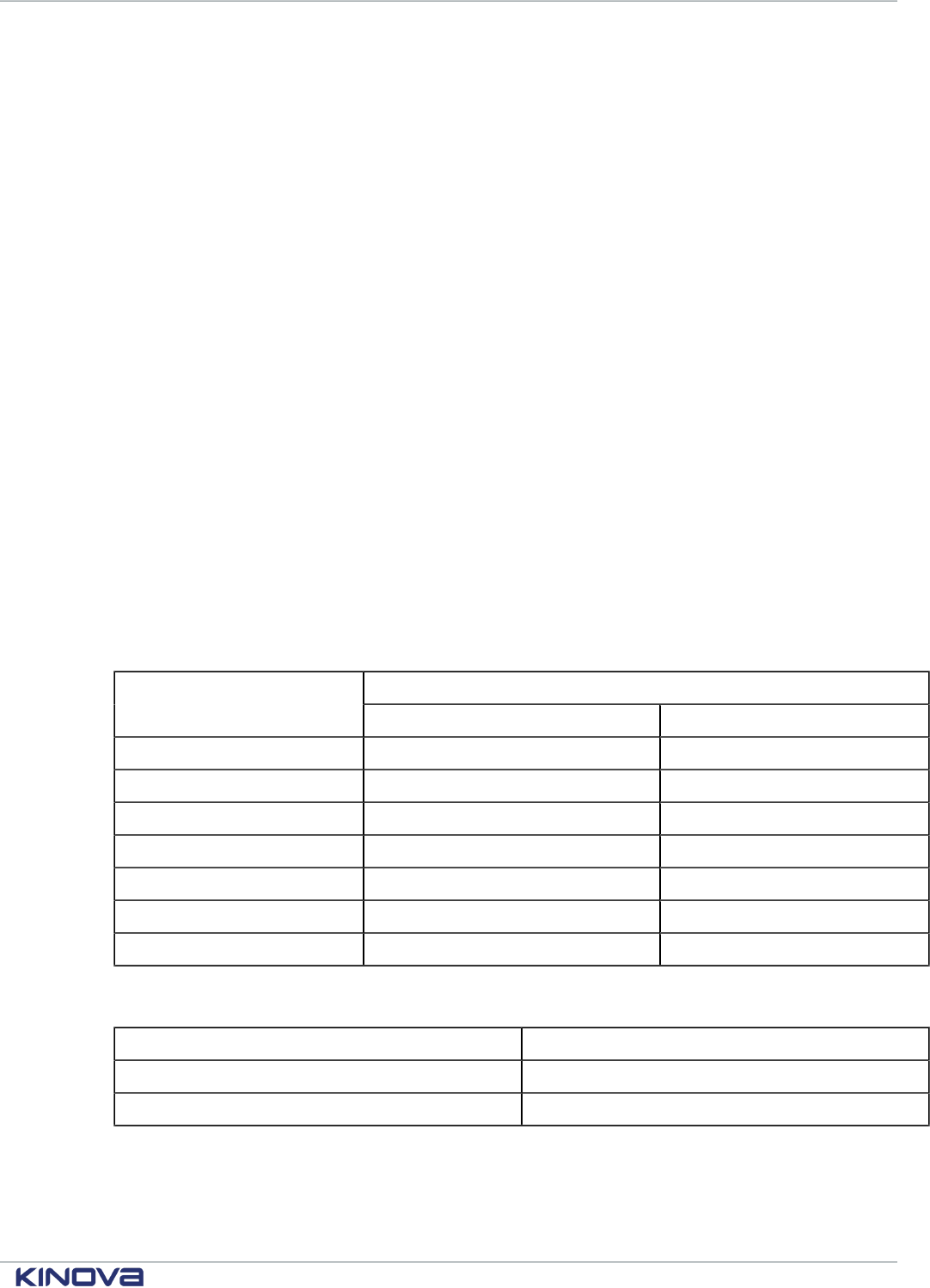
Kinova® Gen3 Ultra lightweight robot User Guide 97
• Cylindrical - position of center, radius, height, and angular orientation of the cylinder are
configurable.
• Spherical - position of center and radius of sphere are configurable
A planar or disc-shaped protection zone can be defined by setting the thickness of the zone to zero
in either a rectangular prism or cylindrical protection zone.
Editing protection zones
Protection zones can be defined, edited, and deleted using either the Web App or the developer API.
Joint limits
The robot has joint limits used in robot high-level control. This impacts the position, speed, acceleration, and
torque applied by the joints.
Overview
When controlling the robot in high-level, the robot control library applies a number of different
joint limits for safety purposes. This includes limits on:
• joint position
• joint speed
• joint acceleration
• joint torques
The limits applied in a particular situation depend on the current high-level control mode.
Gen3 7 DoF spherical wrist robot joint limits
Table 39: Joint position limits
Angular range
Actuator
Lower limit Upper limit
1 - ∞ + ∞
2 - 128.9° + 128.9°
3 - ∞ + ∞
4 - 147.8° + 147.8°
5 - ∞ + ∞
6 - 120.3° + 120.3°
7 - ∞ + ∞
Table 40: Joint speed limits (general limits)
Actuator Limit (magnitude)
large (joints 1 - 4) 79.64 °/s (1.39 rad/s)
small (joints 5 - 7) 69.91 ° / s (1.22 rad/s)
+1 514-277-3777 kinovarobotics.com
© 2022 Kinova inc. All rights reserved.
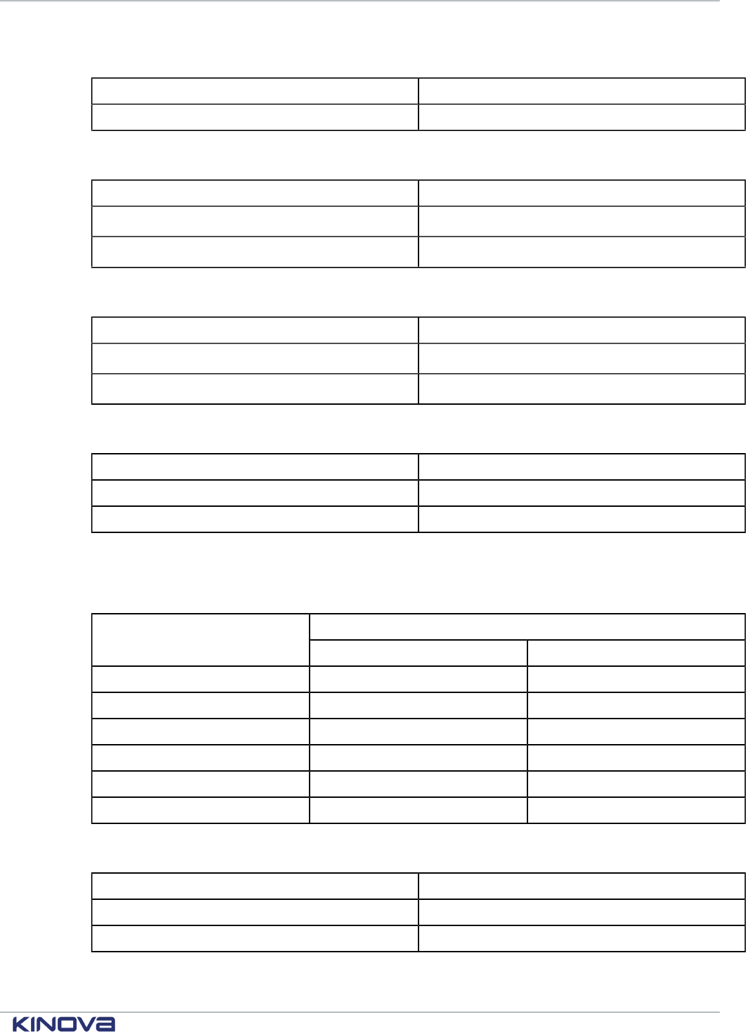
Kinova® Gen3 Ultra lightweight robot User Guide 98
Table 41: Joint speed limits (admittance and force control modes)
Actuator Limit (magnitude)
all joints 50.0 °/s (0.8727 rad/s)
Table 42: Joint acceleration hard limits
Actuator Limit (magnitude)
large (joints 1 - 4)
297.94 °/s
2
(5.2 rad/s
2
)
small (joints 5 - 7)
572.95 ° / s
2
(10.0 rad/s
2
)
Table 43: Joint acceleration limits (angular joystick and joint trajectory)
Actuator Limit (magnitude)
large (joints 1 - 4)
57.3 ° / s
2
(1.0 rad/s
2
)
small (joints 5 - 7)
572.95 ° / s
2
(10.0 rad/s
2
)
Table 44: Joint torques soft limits
Actuators Limit (magnitude)
large (joints 1 - 4) 39.0 N * m
small (joints 5 - 7) 9.0 N * m
Gen3 6 DoF spherical wrist robot joint limits
Table 45: Joint position limits
Angular rangeActuator
Lower limit Upper limit
1 - ∞ + ∞
2 - 128.9° + 128.9°
3 - 147.8° + 147.8°
4 - ∞ + ∞
5 - 120.3° + 120.3°
6 - ∞ + ∞
Table 46: Joint speed limits (general limits)
Actuator Limit (magnitude)
large (joints 1 - 3) 79.64 °/s (1.39 rad/s)
small (joints 4 - 6) 69.91 °/s (1.22 rad/s)
+1 514-277-3777 kinovarobotics.com
© 2022 Kinova inc. All rights reserved.
Kinova® Gen3 Ultra lightweight robot User Guide 99
Table 47: joint speed limits (admittance and force control modes)
Actuator Limit (magnitude)
all joints 50.0 °/s (0.8727 rad/s)
Table 48: Joint acceleration hard limits
Actuator Limit (magnitude)
large (joints 1 - 3)
297.94 °/s
2
(5.2 rad/s
2
)
small (joints 4 - 6)
572.95 °/s
2
(10.0 rad/s
2
)
Table 49: Joint acceleration limits angular joystick and joint trajectory)
Actuator Limit (magnitude)
large (joints 1 - 3)
57.3 ° / s
2
(1.0 rad / s
2
)
small (joints 4 - 6)
572.95 ° / s
2
(10.0 rad / s
2
)
Table 50: Joint torques soft limits
Actuator Limit (magnitude)
large (joints 1 - 3) 39.0 N * m
small (joints 4 - 6) 9.0 N * m
Control modes and relevant joint limits
Control mode Joint limits applied
Cartesian trajectory joint position, joint speed
angular trajectory joint position, joint speed, joint acceleration,
joint torque (for pre-computed trajectories)
Cartesian joystick joint position, joint speed
angular joystick joint position, joint speed, joint acceleration
Cartesian admittance joint angle, joint speed
joint admittance joint angle, joint speed
null space admittance (7 DoF robot only) joint angle, joint speed
Behavior at joint limits
When joint limits are reached, the behavior of the robot will be altered depending on the type of
limitation.
Limit Behavior when limit is reached
joint acceleration joint acceleration will max out at acceleration limit
joint speed acceleration go to zero and joint
speed will max out at speed limit
+1 514-277-3777 kinovarobotics.com
© 2022 Kinova inc. All rights reserved.
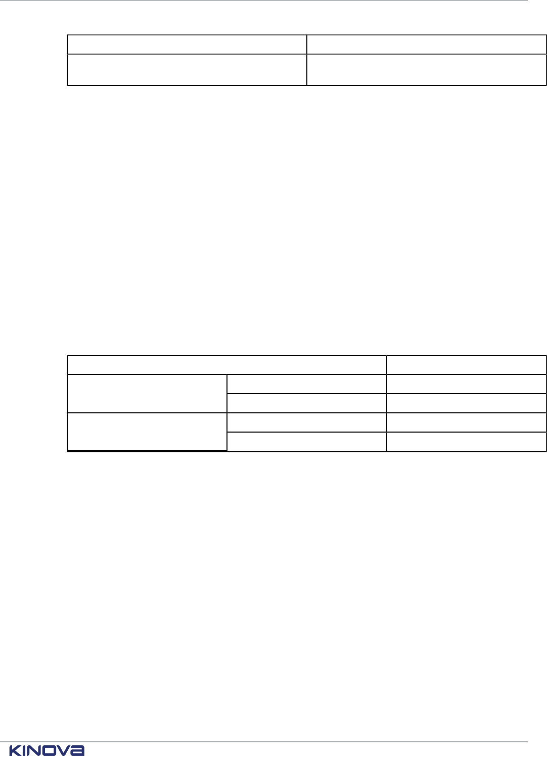
Kinova® Gen3 Ultra lightweight robot User Guide 100
Limit Behavior when limit is reached
joint position joint acceleratation and joint speed goes to zero
and motion of the joint will stop at the position limit
Cartesian limits
The robot has limits on tool motion applying in high-level Cartesian control. These limits apply on top of
underlying joint limits.
Overview
Cartesian limits on the motion of the tool in Cartesian modes (these limits do not apply in angular
modes) are applied as follows:
• In Cartesian joystick, the magnitude (vector norm) of the linear and rotational speeds of the tool
are capped. Twist commands whose linear and / or rotation speed exceed these limits will be re-
scaled proportionally so that the magnitudes of tool linear and angular speeds will not exceed
the limits, but the commanded directions of tool movement will be respected.
• For all Cartesian modes, the individual joint speeds will be capped at their limits. The speed of all
joints will be proportionally scaled so that:
º no individual joint exceeds the speed limit
º the desired direction of motion is respected
• For all Cartesian modes, joint positions will be capped at their limits.
Spherical wrist robot Cartesian limitations
Limit Value
linear 0.5 m/s
twist limits
angular 50 °/s (0.8727 rad/s)
force 40.0 N
wrench limit
torque 15.0 N·m
Configurable limits
Soft Cartesian and joint limits can be configured within the range of hard limits. As well, desired speeds can be
set within the soft limits.
The control library of the robot allows for configuring a number of control mode specific speed and
acceleration limits for the robot.
There are two types of configurations available:
• Soft limits
• Desired speeds
Soft limits
Soft limits can be set for several speed and acceleration values by control mode. Soft limits are
configurable for:
• Cartesian limits
º Tool linear speed
º Tool angular speed
+1 514-277-3777 kinovarobotics.com
© 2022 Kinova inc. All rights reserved.

Kinova® Gen3 Ultra lightweight robot User Guide 101
• Angular limits
º Joints speeds (individually configurable for each joint)
º Joints accelerations (individually configurable for each joint)
Note: Cartesian soft limits are only configurable in Cartesian modes (Cartesian trajectory
and joystick)
Note: Joint acceleration soft limits are only configurable for angular modes (angular
trajectory and joystick)
Note: Soft limits are not configurable in admittance modes nor in low-level control.
Note: Soft limits cannot surpass corresponding robot hard limits.
Desired speeds
Desired speeds can be configured for joystick control modes (angular and Cartesian).
For Cartesian joystick desired tool linear and angular speed can be specfied.
For angular joystick desired joint speeds can be set for each joint.
Note: Desired speeds cannot surpass corresponding soft limits set for that joystick mode. If
the soft limit is reset to below the current configured desired speed, the desired speed will
be lowered to match. Raising the soft limit will not affect the configured desired speed.
Soft limits and desired speeds are configurable via:
• Kinova.Api.ControlConfig API
• Web App Speed Limits page
High-level control modes description
Overview of the high-level control modes of the robot.
The robot is controllable via a number of high-level control modes:
• Trajectory modes
º Sngular trajectory
º Cartesian trajectory
• Joystick control modes
º Cartesian joystick
º Angular joystick
• Admittance modes
º Cartesian admittance
º Joint admittance
º Null space admittance (7 DoF model only)
• Force control modes
º Force control
º Force control motion restricted
+1 514-277-3777 kinovarobotics.com
© 2022 Kinova inc. All rights reserved.

Kinova® Gen3 Ultra lightweight robot User Guide 102
Trajectory control modes
Trajectories define a path of the robot through space, either Cartesian or joint, over a time period. There are
different ways available to define trajectories.
Using trajectory control modes, the user can command the robot to a desired endpoint.
There are a few different ways a trajectory can be defined.
Reach endpoint
Users can provide an endpoint to reach, and the let the control software of the robot compute how
to follow a path to reach the endpoint. The robot controller computes an interpolated trajectory
(between current pose and target pose) to reach the final position while satisfying configured limits,
and commands the robot to follow this trajectory. These trajectories, once defined, can be played
back. This is a good setting when you want the robot to go to a desired end state but you are not
overly concerned about the exact path it follows getting there and exactly how long it takes.
Pre-computed trajectory
Users can supply a pre-computed trajectory to the robot. A pre-computed trajectory is generally
auto-generated by some sort of path planning software or algorithm rather than built manually.
A pre-computed trajectory is defined as a time series of settings for joints angular positions,
velocities, and accelerations at each timestamp. The robot control software will verify that
the trajectory is valid and reasonable, satisfying configured limits. Users can indicate a desired
continuity mode for the trajectory against which the trajectory can be checked (position, or position
and velocity, or position, velocity and acceleration).
The robot control library will perform the following validations on the pre-computed trajectory:
• trajectory is non-empty
• for each trajectory point, position, velocity, and acceleration values must be provided for each
joint in the robot
• trajectory contains no NaN values
• timestamp of the first trajectory point must be 0.000 seconds and the difference in time stamps
between successive points must be 0.001 seconds
• joint positions, speeds, accelerations, and torques must be within robot joint limits
• continuity - the trajectory is continuous in terms of (user can specify which of these continuity
checks to apply):
º position - joint position variation between successive timesteps is less than the maximum
variation (based on joint speed limit)
º speed - speed values are consistent (within tolerances) with derivative of position
º acceleration - acceleration values are consistent (within tolerances) with derivative of speed
• trajectory execution (when starting the trajectory) - the joint positions and speeds for the first
point in the trajectory must match the initial robot joint positions and speeds
Note: For safety reasons, trajectories failing any of the validation checks will be rejected,
and you will receive an error notification. To get more detailed information about why
a particular trajectory failed, use the method GetTrajectoryErrorReport() in
Kinova.Api.Base.
Trajectory modes
In Cartesian Trajectory mode, the positions are defined in terms of the desired Cartesian space
pose of the tool frame. This mode enables singularity avoidance. Cartesian trajectory mode can be
+1 514-277-3777 kinovarobotics.com
© 2022 Kinova inc. All rights reserved.
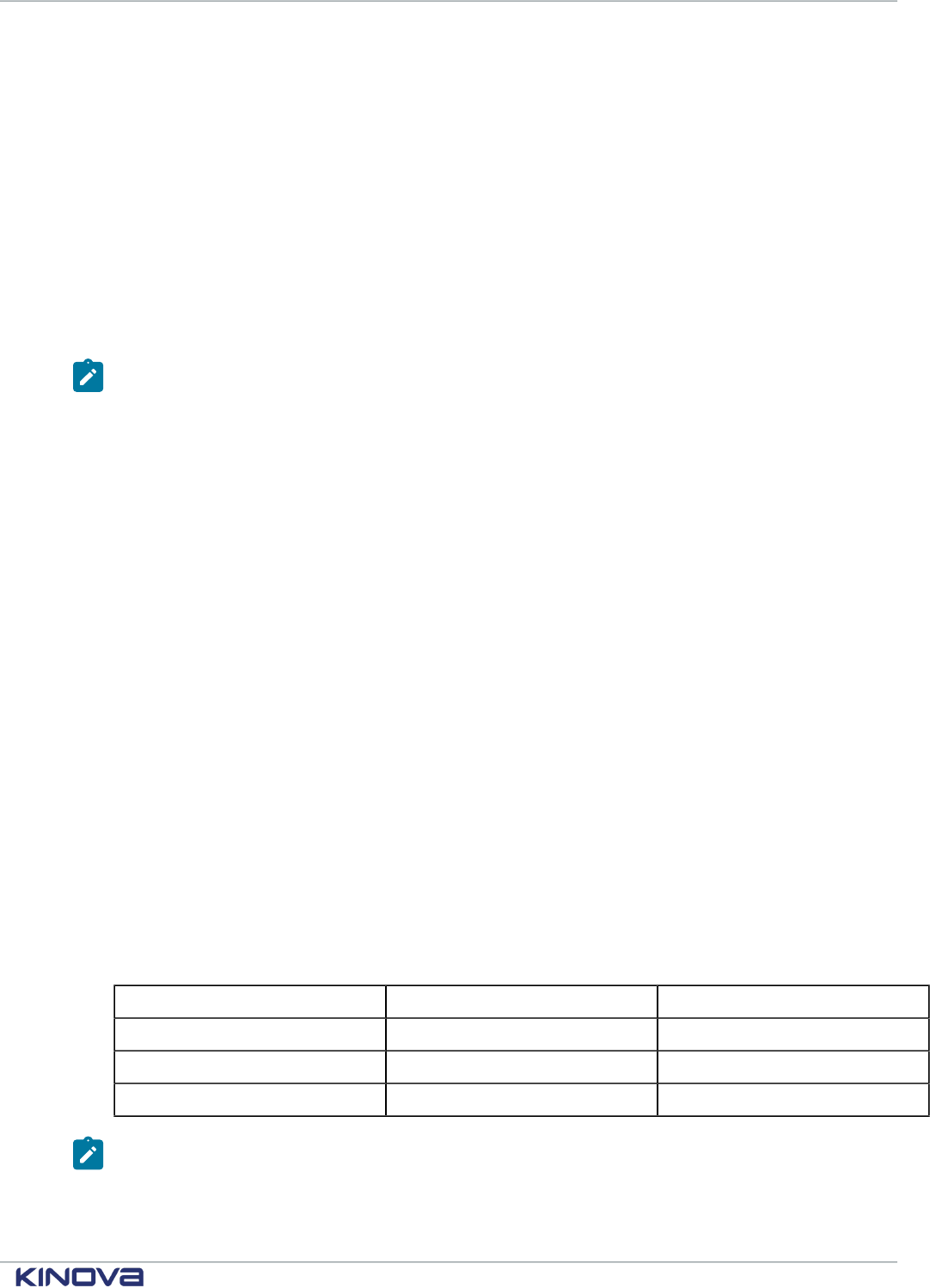
Kinova® Gen3 Ultra lightweight robot User Guide 103
activated by sending a pose endpoint or a list of Cartesian waypoints. Cartesian Trajectory mode is
not compatible with pre-computed trajectories.
In Angular Trajectory mode the positions are defined in terms of the desired joint angles for the
actuators. Angular Trajectory mode can be activated by sending an endpoint joint state, a list of
angular waypoints, or a pre-computed trajectory.
Users have the option to apply constraints to trajectories. There are three options available for
constraints:
• Duration - the time period (in seconds) in which the trajectory is to be carried out
• Speed - the maximum speed (meters/second for Cartesian, degrees/second for angular) of the
motion while carrying out the trajectory
• No constraint - the robot will go to the endpoint without the time or speed being specified
Note: If a requested trajectory constraint will cause angular limits to be exceeded in the
course of the trajectory, (e.g. the duration is too short and requires a speed or acceleration
that is not feasible) the trajectory will be rejected.
In angular trajectories, all three options are available (duration, speed, no constraint).
In Cartesian trajectories, the speed constraint or no constraint options are available.
Trajectory control modes are set by sending a trajectory using the appropriate API methods, or the
Web App Actions page.
Joystick control modes
Joystick control modes allow the robot to be controlled by sending motion (speed) commands by either
Cartesian or joint.
Joystick Control modes provide the user the ability to create a desired motion of the robot by
sending commands to the robot. This is done using joystick control inputs (physical gamepad or
virtual joystick) or directly using API commands.
In Cartesian Joystick mode the motion of the robot end effector, both linear and angular, is
controlled. Cartesian Joystick is entered by:
• sending API twist commands (specify linear and angular velocity of the end effector)
• activating Xbox gamepad Twist linear and Twist angular modes
• sending Web App Pose virtual joystick control inputs in velocity control
This mode provides for singularity avoidance and obstacle avoidance (protection zones).
For Cartesian control, the reference frames for translation and orientation control are configurable:
Table 51: Cartesian reference frames options
Cartesian frame mode Reference frame for translation Reference frame for orientation
mixed mode base tool
tool mode tool tool
base mode base base
Note: Orientations are defined using an x-y-z extrinsic convention. That is, rotation about
the fixed x-axis, followed by rotation about the fixed y-axis, followed by rotation about the
fixed z-axis.
+1 514-277-3777 kinovarobotics.com
© 2022 Kinova inc. All rights reserved.

Kinova® Gen3 Ultra lightweight robot User Guide 104
In Angular Joystick mode the joints of the robot are moved in angular space using joint angular
velocity commands or joystick control inputs provided to the actuators. The joints can be moved
individually or together.
Angular joystick mode can be entered by:
• sending API joint speed commands
• activating Xbox gamepad Joint mapping
• sending commands via Web App Angular virtual joystick
Admittance modes
There are multiple admittance modes on the robot allowing admittance control.
There are multiple admittance modes on the robot allowing for different types of admittance
control.
In Cartesian admittance mode, the user manipulates the robot, and exerted effort is interpreted
as an effort exerted on the tool. A spherical workspace centered on actuator two is defined. If the
user tries to extend the robot beyond this workspace, the robot will resist and come back inside the
workspace.
In joint admittance mode the joints of the robot rotate according to the external torques applied.
In null space admittance mode, the tool stays in the same pose while the user manipulates the
joints of the robot (within the null space). The robot moves within the null space according to the
torques applied.
Note: Null space admittance is not available for the 6 DoF robot model.
Note: For all three admittance modes, the robot control library will automatically adapt to
the user-configured gravity vector, tool, and payload information. The user is responsible
for correctly defining the gravity vector, as well as tool and payload information using either
the Web App or API (Kinova.Api.ControlConfig). Incorrect configuration of these
parameters can cause unexpected behavior in admittance modes.
There are four ways to put the robot into admittance:
• use the method SetAdmittance in the API.
• Web App control panel admittance mode selection
• admittance selection buttons on Xbox gamepad modes (Twist linear and angular modes for
Cartesian and Null space admittance, Joint mode for Joint admittance)
• admittance mode physical buttons on the interface module.
Note: Motion in admittance modes is constrained by internal safety limits for the robot on
velocity and torques. This includes Cartesian linear velocity limits and joint limits for angular
velocity and torque.
Force Control modes
The robot can be controlled in Force control mode. A wrench command defining force and torque is applied
to the robot tool. A constraint can be applied restricting the resulting motion in the direction of the desired
wrench.
In Force Control mode, a wrench command (force and torque) is sent to the tool. This allows you to
use the tool to apply a desired force and torque on an external object.
In force control mode the tool will also accept external forces as in Cartesian admittance mode.
+1 514-277-3777 kinovarobotics.com
© 2022 Kinova inc. All rights reserved.
Kinova® Gen3 Ultra lightweight robot User Guide 105
The tool will move according to the resultant of the commanded and external forces.
When a wrench command is sent to the robot, the corresponding accelerations (linear and angular)
will be applied to the tool until:
• a new command is received, or
• Cartesian or joint limits are reached
Force Control Motion Restricted is a sub-mode of Force Control mode in which the resulting
motion of the end effector is constrained to the direction of the desired wrench.
Force Control can be entered by sending a Wrench command via API commands.
Low-level control detailed description
Low-level control is achieved by using the UDPTransportClient command over port 10001.
The command establishes a communication channel between API cyclic clients and the robot at a
rate of 1 kHz. The cyclic clients provide methods to obtain feedback from the sensors and to send
commands directly to devices; using the cyclic client methods bypasses the regular overhead from
the controller.
Important: Use UDPTransportClient over port 10001 when the API client intends to
communicate with the robot at 1 kHz.
Low-level control implementation
The level of risk between receiving low-level feedback and sending low-level commands differs. It is
important to understand how to implement low-level control of the robot.
A full list of methods for low-level functionality is in the topic High-level and low-level robot control
methods reference on page 92.
CAUTION: Low-level control, and torque control in particular, is intended for advanced
users only.
Any cyclic client under any condition can use the method RefreshFeedback() to access feeback.
However, the arm must be in one of two modes for commands to be sent using the low-level API.
• Low-level servoing mode
• Low-level bypass servoing mode
Note: Use the method SetServoingMode(ServoingModeInformation) of the Base
client to switch the servoing mode of the robot.
Low-level servoing mode uses the BaseCyclic client to send low-level commands to the robot as
a system. This is the recommended way to use the low-level API.
Use low-level bypass to route messages directly to the devices by creating a cyclic client for each
device.
Remember: A device is an actuator, interconnect, or gripper.
Users are responsible for creating a high-frequency command loop at a rate of 1 kHz and for
decomposing desired robot movements into small command increments for actuators and gripper
motors. These command increments are sent sequentially to the robot base at a 1 kHz frequency
using this real-time session. The robot base then routes these individual command increments to
the actuators and gripper using its own 1 kHz cyclic communications with the robot devices. Each
individual command increment must be executed within the 1 ms time interval.
+1 514-277-3777 kinovarobotics.com
© 2022 Kinova inc. All rights reserved.

Kinova® Gen3 Ultra lightweight robot User Guide 106
Carry out low-level control of the robot through the Kinova.Api.BaseCyclic API.
When the robot is in any of the low-level servoing modes, actuators can be sent specific commands.
• Joint position
• Joint speed
• Joint torque
• Joint motor current
When the robot is in any of the low-level servoing modes, grippers can be sent specific commands.
• Gripper finger position
• Gripper finger velocity
Use the method SetControlMode(ControlModeInformation) from the ActuatorConfig
client to select the type of command you wish to send to the actuator. After the type of actuator
command is selected, fill in the appropriate command structures and send them to the robot using
the method Refresh(Command). Send these commands at a rate of 1 kHz.
Note: When command types other than Joint positions are sent to actuators, always include
the position returned by the latest actuator feedback in the command; actuator positions are
used to monitor following errors.
Note: When command types other than Joint positions are sent to actuators, always include
the position returned by the latest actuator feedback in the command; actuator positions are
used to monitor following errors.
For more details on how to implement low-level control, including API documentation and code
examples, please see the Kortex GitHub repository: https://github.com/kinovarobotics/kortex.
Low-level feedback
Each device on the robot has a cyclic client API service associated with it that defines the components of the
feedback available for each device.
Devices on the robot
• Base
• Actuators
• Interconnect
• Gripper
Table 52: Content of the Feedback structure defined by the BaseCyclic client
frame_id Identification number. Corresponds to the frame_id of the command sent.
base BaseFeedback object containing the feedback of the robot as a system
actuators Array of ActuatorFeedback objects containing the feedback of each
actuator
interconnect Interconnect Feedback object containing the feedback from the
interconnect module.
+1 514-277-3777 kinovarobotics.com
© 2022 Kinova inc. All rights reserved.
Kinova® Gen3 Ultra lightweight robot User Guide 107
Table 53: Content of the BaseFeedback structure defined by the BaseCyclic client
active_state_connection_identifierConnection identifier of the last processed command which triggered an
arm state change
active_state Active state of the arm
arm_voltage Voltage applied on the arm (V)
arm_current Current applied on the arm (A)
temperature _cpu CPU temperature (°C)
temperature_ambient Ambient temperature (°C)
imu_acceleration_x
IMU measured acceleration along the X-axis (m/s
2
)
imu_acceleration_y
IMU measured acceleration along the Y-axis (m/s
2
)
imu_acceleration_z
IMU measured acceleration along the Z-axis (m/s
2
)
imu_angular_velocity_x IMU measured angular velocity along the X-axis (°/s)
imu_angular_velocity_y IMU measured angular velocity along the Y-axis (°/s)
imu_angular_velocity_z IMU measured angular velocity along the Z-axis (°/s)
tool_pose_x Measured cartesian position of the TCP along the X-axis (m)
tool_pose_y Measured cartesian position of the TCP along the Y-axis (m)
tool_pose_z Measured cartesian position of the TCP along the Z-axis (m)
tool_pose_theta_x Measured cartesian orientation of the TCP along the X-axis (°)
tool_pose_theta_y Measured cartesian orientation of the TCP along the Y-axis (°)
tool_pose_theta_z Measured cartesian orientation of the TCP along the Z-axis (°)
tool_twist_linear_x Measure cartesian linear velocity of the TCP along the X-axis (m/s)
tool_twist_linear_y Measure cartesian linear velocity of the TCP along the Y-axis (m/s)
tool_twist_linear_x Measure cartesian linear velocity of the TCP along the Z-axis (m/s)
tool_twist_angular_x Measure cartesian angular velocity of the TCP along the X-axis (°/s)
tool_twist_angular_y Measure cartesian angular velocity of the TCP along the Y-axis (°/s)
tool_twist_angular_z Measure cartesian angular velocity of the TCP along the Z-axis (°/s)
tool_external_wrench_force_x Computed force applied on the TCP along the X-axis
tool_external_wrench_force_y Computed force applied on the TCP along the Y-axis
tool_external_wrench_force_z Computed force applied on the TCP along the Z-axis
tool_external_wrench_torque_x Computed torque applied on the TCP along the X-axis
tool_external_wrench_torque_y Computed torque applied on the TCP along the Y-axis
tool_external_wrench_torque_z Computed torque applied on the TCP along the Z-axis
fault_bank_a The arm fault flags bank A (0 if no fault)
fault_bank_b The arm fault flags bank B (0 if no fault)
warning_bank_a The arm warning flags bank A (0 if no warning)
+1 514-277-3777 kinovarobotics.com
© 2022 Kinova inc. All rights reserved.
Kinova® Gen3 Ultra lightweight robot User Guide 108
warning_bank_b The arm warning flags bank B (0 if no warning)
commanded_tool_pose_x Commanded cartesian position of the TCP along the X-axis (m)
commanded_tool_pose_y Commanded cartesian position of the TCP along the Y-axis (m)
commanded_tool_pose_z Commanded cartesian position of the TCP along the Z-axis (m)
commanded_tool_pose_theta_x Commanded cartesian orientation of the TCP along the X-axis (°)
commanded_tool_pose_theta_y Commanded cartesian orientation of the TCP along the Y-axis (°)
commanded_tool_pose_theta_z Commanded cartesian orientation of the TCP along the Z-axis (°)
Table 54: Content of the ActuatorFeedback structure defined by the BaseCyclic client
command_id Command ID
status_flags (internal use only)
jitter_comm Jitter from the communication (us)
position Position of the actuator (°)
velocity Velocity of the actuator (°/s)
torque Torque applied on the actuator (Nm)
current_motor Current applied on the motor (A)
voltage Voltage applied on the main board (V)
temperature_motor Maximum temperature of the three motor phases (°C)
temperature_core Microcontroller temperature (°C)
fault_bank_a The actuator fault flags bank A
fault_bank_b The actuator fault flags bank B
warning_bank_a The actuator warning flags bank A
warning_bank_b The actuator warning flags bank B
Table 55: Content of the Feedback structure defined by the InterconnectCyclic client
feedback_id ID of the frame the feedback is associated to
status_flags (internal use only)
jitter_comm Jitter from the communication (us)
imu_acceleration_x
IMU measured acceleration along the X-axis (m/s
2
)
imu_acceleration_y
IMU measured acceleration along the Y-axis (m/s
2
)
imu_acceleration_z
IMU measured acceleration along the Z-axis (m/s
2
)
imu_angular_velocity_x IMU measured angular velocity along the X-axis (°/s)
imu_angular_velocity_y IMU measured angular velocity along the Y-axis (°/s)
imu_angular_velocity_z IMU measured angular velocity along the Z-axis (°/s)
voltage Voltage of the main interconnect board (V)
+1 514-277-3777 kinovarobotics.com
© 2022 Kinova inc. All rights reserved.
Kinova® Gen3 Ultra lightweight robot User Guide 109
temperature_core Microcontroller temperature (°C)
fault_bank_a Interconnect fault bank A
fault_bank_b Interconnect fault bank B
warning_bank_a Interconnect warning bank A
warning_bank_b Interconnect warning bank B
tool_feedback Feedback as defined by the GripperCyclic client
Table 56: Content of the Feedback structure defined by the GripperCyclic client
feedback_id ID of the feedback frame
status_flags Status flags
fault_bank_a Interconnect fault bank A
fault_bank_b Interconnect fault bank B
warning_bank_a Interconnect warning bank A
warning_bank_b Interconnect warning bank B
motor Array of MotorFeedback objects as defined by the GripperCyclic client
Table 57: Content of the MotorFeedback structure defined by the GripperCyclic client
motor_id ID of the gripper motor
position Position of the gripper fingers (%)
velocity Velocity of the fingers (% of max)
current_motor Current consumed by the gripper motor (mA)
voltage Motor voltage (V)
temperature_motor Motor temperature (°C)
Low-level commands
In addition to feedback, the cyclic client for each type of device also defines the components of the commands
that can be sent to each device in real-time.
Table 58: Content of the Command structure defined by the BaseCyclic client
frame_id Identifier that will be associated to the feedback obtained in the same
frame the command is processed
actuators An array of ActuatorCommand objects, which should contain commands
for every actuator
interconnect An InterconnectCyclic Command object.
Table 59: Content of the ActuatorCommand structure defined by the BaseCyclic client
command_id ID of the command (first 2 bytes: device ID, last 2 bytes: sequence
number)
+1 514-277-3777 kinovarobotics.com
© 2022 Kinova inc. All rights reserved.
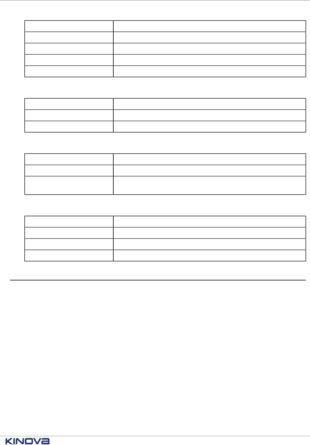
Kinova® Gen3 Ultra lightweight robot User Guide 110
flags Actuator Command flags as defined by the ActuatorCyclic service
position Desired position of the actuator (°)
velocity Desired velocity of the actuator (°/s)
torque_joint Desired torque of the actuator (Nm)
current_motor Desired current applied to the motor (A)
Table 60: Content of the Command structure defined by the InterconnectCyclic client
command_id ID of the command
status_flags Status flags
gripper_command Command structure as defined by the GripperCyclic client
Table 61: Content of the Command structure defined by the GripperCyclic client
command_id ID of the command
flags Flags
motor_cmd An array of MotorCommand objects as defined by the GripperCyclic
client (one object for each finger of the gripper)
Table 62: Content of the MotorCommand structure defined by the GripperCyclic client
motor_id Motor ID
position Desired position of the gripper fingers (%)
velocity Desired velocity of the gripper fingers (% of max value)
force Deprecated - unused
Waypoint trajectories
Kortex API version 2.3.0 released with the concept of Waypoint trajectories, which can be used to make the
robot follow a trajectory of multiple points and smoothly transitioning between them without stopping.
ExecuteWaypointTrajectory(WaypointList) is a method made available by the Base
service that makes the robot execute a trajectory defined by a waypoint list.
A waypoint list contains an array of one or more waypoints, as well as a boolean flag labeled
use_optimal_blending , which automatically smooths the transition between waypoints to minimize
the total time to execute the trajectory.
A waypoint is defined by a name, which can be configured, and a waypoint type, which has to be
either an AngularWaypoint or CartesianWaypoint. Note that a waypoint list can only contain
waypoints of a single type.
Angular waypoints
Angular waypoint trajectories are defined by a series of joint poses, defined in degrees, interpolated using
cubic splines.
Each angular waypoint in the list is associated with a configurable duration, which defines how
much time the trajectory takes to reach the waypoint. Each waypoint can also define maximum
+1 514-277-3777 kinovarobotics.com
© 2022 Kinova inc. All rights reserved.

Kinova® Gen3 Ultra lightweight robot User Guide 111
velocities, which are constraints that must be maintained by each joint to reach the associated
point.
Cartesian waypoints
Cartesian waypoint trajectories are defined by a series of Cartesian poses. Each waypoint can define its pose
in a reference frame, as defined by the Common API service.
Optionally, maximum linear and angular velocities can be set as constraints during the motion to
reach a given waypoint. Note that these constraints are maximum values only. Should there not be
enough space between two waypoints to accelerate to this speed, it is normal that this speed is not
reached.
When generating the trajectory, the robot moves in a straight line from one waypoint to the next
waypoint, until the distance between the TCP of the robot and the next waypoint becomes smaller
than the value defined as the blending radius. When the distance is smaller than the blending
radius, the robot starts moving toward the waypoint after that on the list.
Figure 41: Trajectory of robot moving from point A to point C using a blending radius on point B
Validation of a waypoint list
The API Base service provides a method called ValidateWaypointList(WaypointList).
After running this method, the robot returns a WaypointValidationReport. When the
use_optimal_blending flag is set to true for the waypoint list, the report includes a copy of the
waypoint list with the optimal blending radii set for each waypoint.
In addition to the trajectory, the WaypointValidationReport contains a TrajectoryErrorReport,
which in turn contains a TrajectoryErrorElement for each error identified in the trajectory during
validation.
+1 514-277-3777 kinovarobotics.com
© 2022 Kinova inc. All rights reserved.
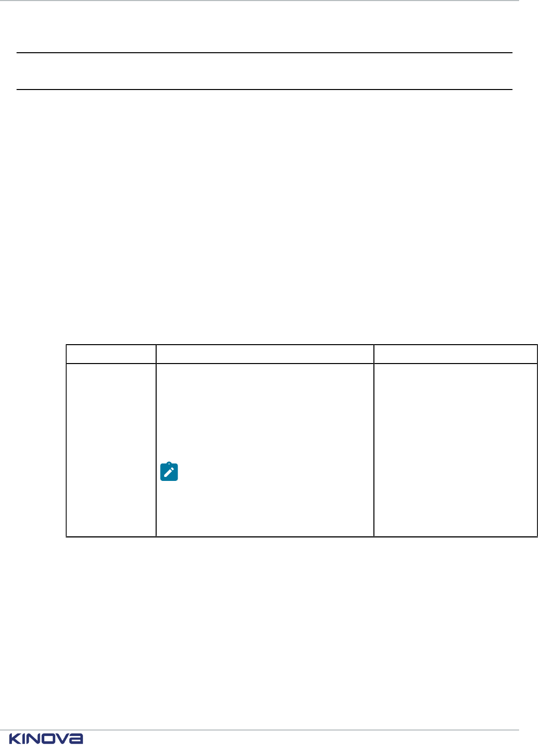
Kinova® Gen3 Ultra lightweight robot User Guide 112
Configurations and safeties
Configurable parameters
There are a number of parameters of the robot that are configurable to customize the operation of the robot.
These can be configured using the API and Web App.
These parameters can be configured using the appropriate Kinova™ Kortex
®
APIs. For more details
on how to perform configuration using the APIs, see the API documentation.
Some of these parameters can also be configured using the Web App GUI, which can be accessed as
follows:
1. Open the Web App.
2. Navigate to the Robot Configurations page.
3. Access configurable parameters on one of the available tabs.
The following tables give a summary of the configurable parameters.
Control library configuration
Control library configuration items configure the functioning of the robot control library. These can be
configured via the API or the Web App.
Table 63: Control modes configuration
Configurable item Description Where to configure it
Gravity vector
Defines global value for gravitational
acceleration vector (x,y,z) in relation to the base
frame in units of m/s
2
.
Note: Configuration of the gravity
vector is necessary to mount the
robot in arbitrary orientations (e.g.
wall mount, ceiling mount). Accurate
configuration of the direction and
strength of gravity is important for
the robot to properly compensate
for torques due to gravity on the
robot actuators.
Kinova.Api.ControlConfig
API
Web App > Configurations >
Robot > Arm
+1 514-277-3777 kinovarobotics.com
© 2022 Kinova inc. All rights reserved.
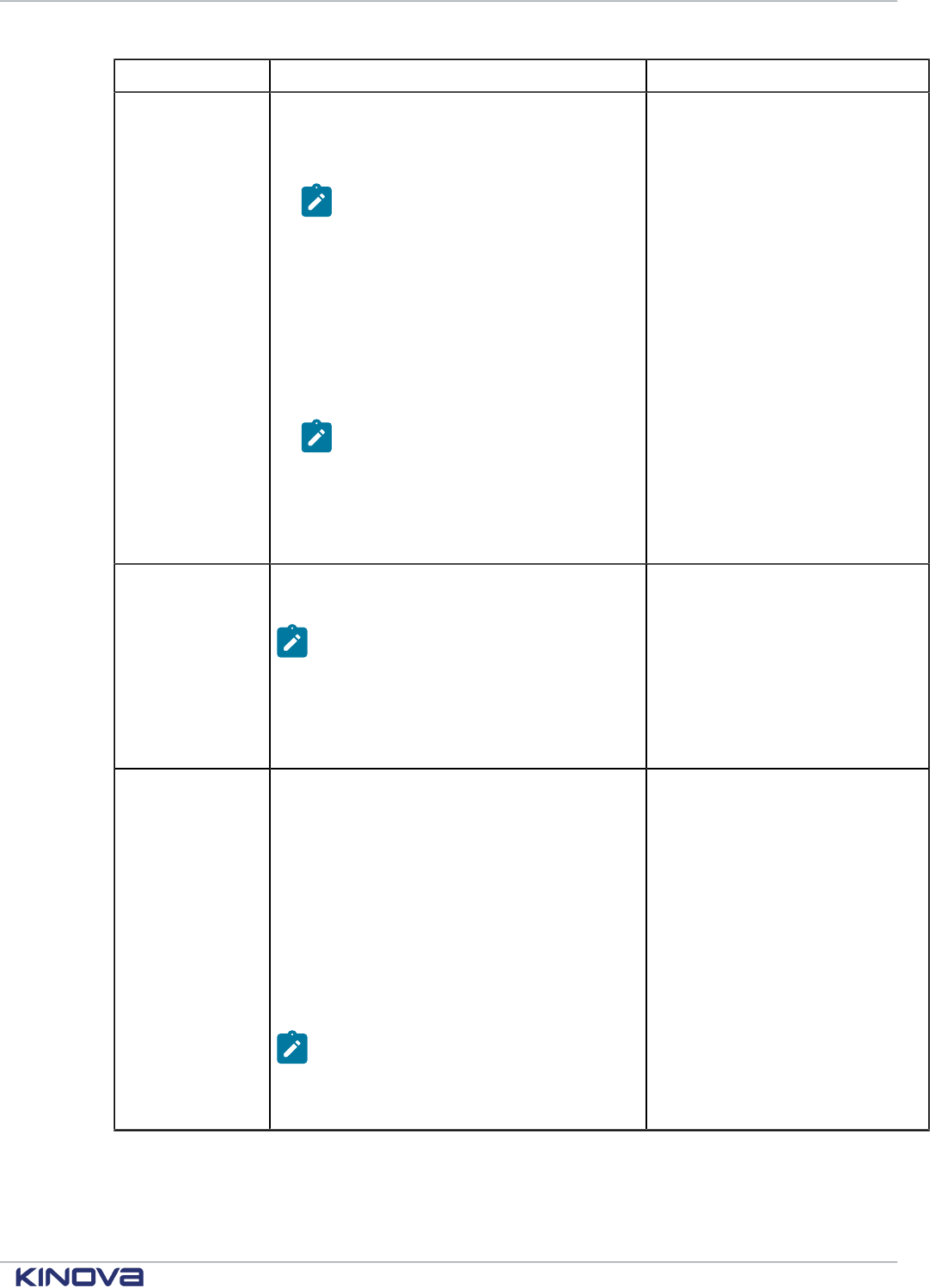
Kinova® Gen3 Ultra lightweight robot User Guide 113
Configurable item Description Where to configure it
Tool configuration
• Set Cartesian transform of x, y, z (m) and θ
x
,
θ
y
, and θ
z
of tool frame in relation to interface
module frame.
Note: The Cartesian pose
feedback available in base cyclic
communications uses the pose of
the tool frame in relation to the
base frame. The specific choice
of the tool frame will therefore
impact the readings for the
current Cartesian pose.
• Set tool mass (kg), and tool mass center
position x, y, z (m)
Note: The mass and center
of mass of the tool need to be
configured for the robot control
libraries to properly adapt
the control of the robot to the
additional mass of the tool.
Kinova.Api.ControlConfig
API
Web App > Configurations >
Robot > Arm
Payload
configuration
Set payload mass (kg) and mass center of
payload x,y,z (m) in relation to the tool frame.
Note: The mass and center of mass
of the payload need to be configured
for the robot control libraries to
properly adapt the control of the
robot to the additional mass of the
payload.
Kinova.Api.ControlConfig
API
Web App > Configurations >
Robot > Arm
Cartesian
reference frame
Set the reference frame convention for
translation and orientation to use with Cartesian
Twist and Wrench commands. There are three
options:
• Mixed - translation reference frame = base
frame and orientation reference frame = tool
frame
• Tool - tool reference frame used for both
translation and orientation reference frames
• Base - base reference frame used for both
translation and orientation reference frames
Note: Changing the reference frame
convention will affect the readings
that are provided for the current
Cartesian pose of the tool.
Kinova.Api.ControlConfig
API
Web App > Pose virtual joystick
+1 514-277-3777 kinovarobotics.com
© 2022 Kinova inc. All rights reserved.
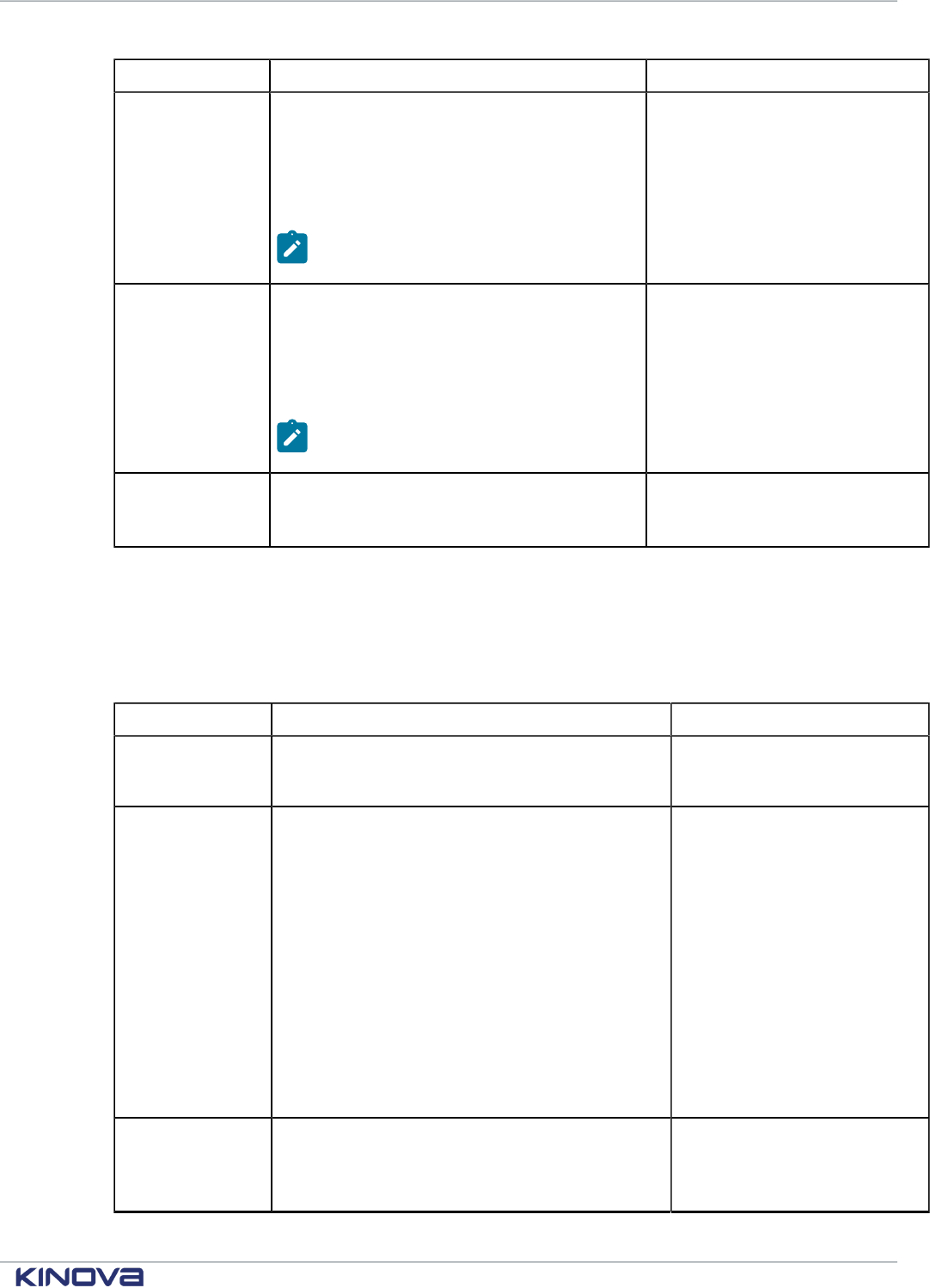
Kinova® Gen3 Ultra lightweight robot User Guide 114
Configurable item Description Where to configure it
Soft limits
Set various soft limits for the robot kinematics in
a specified control mode:
• tool twist linear and angular speed
• joint speed (for each joint)
• joint acceleration (for each joint)
Note: Soft limits must be less than
corresponding robot hard limits
Kinova.Api.ControlConfig
API
Web App > Configurations >
Speed Limits
Desired speeds
Set desired speeds for joystick control modes:
• tool twist linear and angular speed (in
Cartesian joystick)
• joint speeds (for each joint, in angular
joystick)
Note: Desired speeds must be less
than corresponding soft limits
Kinova.Api.ControlConfig
API
Web App > Pose / Angular
virtual joysticks
Axis lock
Set locks to prevent the tool from linear or
angular movement in / around specified axes in
specified control modes.
Kinova.Api.ControlConfig
API
Base configuration
Base configurations cover a range of core configurable items. These can be configured via the API or the Web
App.
Table 64: Base configuration
Configurable item Description Where to configure it
User Profiles Create, read, update and delete user profiles
Kinova.Api.Base API
Web App > Users
Protection Zone
Create, read, update and delete protection zones
(for obstacle avoidance). Configurable parameters
are:
• enabled/disabled
• zone shape type (rectangular prism, cylinder,
sphere)
• zone origin and orientation
• zone dimensions
• envelope thickness
• zone limitation types (force, acceleration,
velocity) and values
• envelope limitation types (force, acceleration,
velocity) and values
Kinova.Api.Base API
Web App > Operations >
Protection Zones
Control Mapping Create, read control mapping
Kinova.Api.Base API
Web App > Configuration >
Controllers
+1 514-277-3777 kinovarobotics.com
© 2022 Kinova inc. All rights reserved.
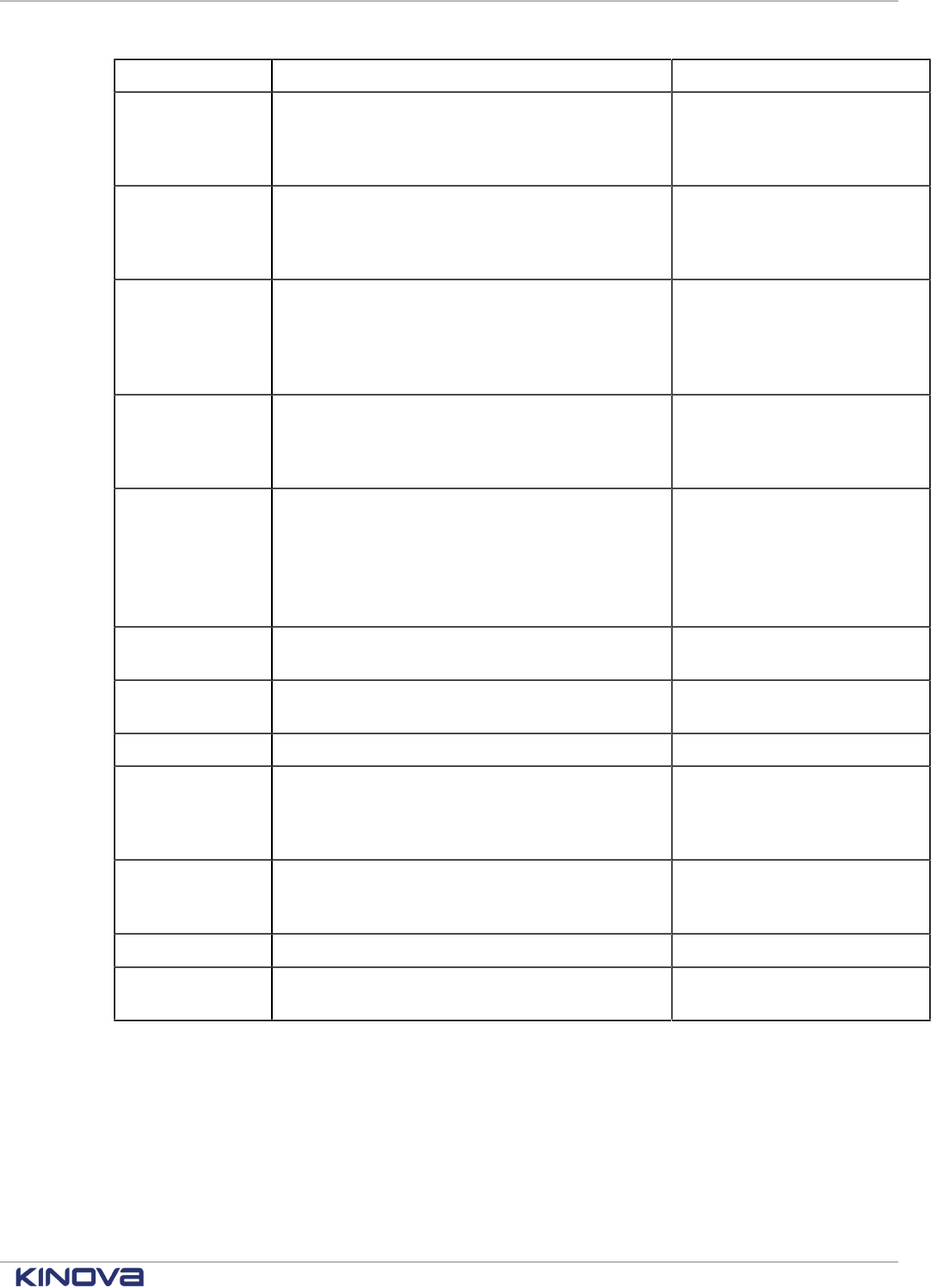
Kinova® Gen3 Ultra lightweight robot User Guide 115
Configurable item Description Where to configure it
Action Create, read, update, delete action
Kinova.Api.Base API
Web App > Operations >
Actions
Sequence Create, read, update, delete a sequence of actions
Kinova.Api.Base API
Web App > Operations >
Actions
IPv4
Set IPv4 configured (for specified network adapter):
• IP address
• subnet mask
• default gateway
Kinova.Api.Base API
Web App > Configurations >
Wireless & Networks
Communication
Interface
Enable communication interface:
• network type (Wi-Fi or Ethernet)
• enabled/disabled
Kinova.Api.Base API
Web App > Configurations >
Wireless & Networks
Wi-Fi
Set:
• SSID
• security key
• automatic connection allowed
• country code
Kinova.Api.Base API
Web App > Configurations >
Wireless & Networks
TCP bridge
to hardware
Enable or disable
Kinova.Api.Base API
Joint Limitation
Set global limit for specified joint and limitation
type.
Kinova.Api.Base API
System time Set system time
Kinova.Api.Base API
Restore factory
settings
Delete all configurations and reverts settings to
factory defaults (except network settings)
Kinova.Api.Base API
Web App > Configurations >
Robot > Arm
Restore factory
product
configuration
Restore product configuration to factory product
configuration
Kinova.Api.Base API
Network settings Restore network factory defaults
Kinova.Api.Base API
Configuration
backups
Create, read, update, and delete configuration
backups
Kinova.Api.Base API
Actuators configuration
Actuators configurations set items related to the functioning of the actuators. Most of these can be
configured only via the API. Zeroing of the actuators torque offsets can be done via the Web App.
+1 514-277-3777 kinovarobotics.com
© 2022 Kinova inc. All rights reserved.
Kinova® Gen3 Ultra lightweight robot User Guide 116
Table 65: Actuator configuration (Kinova.Api.ActuatorConfig)
Configurable item Description Where to configure it
Axis offsets Set actuator axis offset position
Kinova.Api.ActuatorConfig
API
Torque offset
Set actuator torque zero configuration Kinova.Api.ActuatorConfig
API
Web App > Configurations >
Robot > Actuators
Control mode
Set actuator control mode. Options:
• position
• velocity
• current
• torque
Kinova.Api.ActuatorConfig
API
Control loop
parameters
Configure an individual control loop
parameter:
• joint or motor position
• joint or motor velocity
• joint torque
• motor current
Configure:
• error saturation value
• output saturation value
• kAz
• kBz
• error dead band value
Kinova.Api.ActuatorConfig
API
Vector drive
parameters
Set vector drive parameters:
• kpq
• kiq
• kpd
• kid
Kinova.Api.ActuatorConfig
API
Encoder derivative
parameters
Set encoder derivative parameters:
• maximum window width
• minimum encoder tick count
Kinova.Api.ActuatorConfig
API
Command mode
Set command mode. Options:
• cyclic - cyclic data only
• asynchronous - configuration messages
only
• cyclic jitter compensation using position or
posi tion and velocity inputs
Note: These options are
available in the API but should
NOT be used
Kinova.Api.ActuatorConfig
API
+1 514-277-3777 kinovarobotics.com
© 2022 Kinova inc. All rights reserved.
Kinova® Gen3 Ultra lightweight robot User Guide 117
Configurable item Description Where to configure it
Servoing
Enable servoing Kinova.Api.ActuatorConfig
API
Interface configuration
Interface configurations impact settings for interface expansion signals. These can be configured via the API
or the Web App.
Table 66: Interface configuration (Kinova.Api.InterconnectConfig)
Configurable item Description Where to configure it
UART communciations Configure interface UART -
enable/disable, speed, word
length, stop bits, parity
Kinova.Api.InterconnectConfig
API
Web App > Configurations > Robot >
Interconnect
Ethernet communications Configure interface
Ethernet port - speed,
duplex mode
Kinova.Api.InterconnectConfig
API
Web App > Configurations > Robot >
Interconnect
GPIO Configure interface GPIOs
- mode, pull mode, value,
default value
Kinova.Api.InterconnectConfig
API
Web App > Configurations > Robot >
Interconnect
I2C Configure interface I2C
- enable / disable, mode,
addressing mode
Kinova.Api.InterconnectConfig
API
Web App > Configurations > Robot >
Interconnect
Device configuration
Device configurations impact settings for robot devices. These can be configured via the API.
Table 67: Device configuration
Configurable item Description Where to configure it
Run mode
Set device run mode (Run, Calibration,
Configuration, Debug, Tuning)
Kinova.Api.DeviceConfig API
IPv4 settings
(For devices other than base) Set device IPv4
address, subnet mask, default gateway
Kinova.Api.DeviceConfig API
Safeties
Enable/disable, set warning and/or error
threshholds for specific safeties
Kinova.Api.DeviceConfig API
Vision configuration
Vision configurations tune the settings for the vision module color and depth sensors. These can be
configured via the API or the Web App.
+1 514-277-3777 kinovarobotics.com
© 2022 Kinova inc. All rights reserved.
Kinova® Gen3 Ultra lightweight robot User Guide 118
Table 68: Vision configuration
Configurable item Description Where to configure it
Sensor settings
Set several discrete vision sensor settings:
Color sensor
• resolution - 320 x 240, 640 x 480, 1280 x 720,
1920 x 1080
• frame rate - 15 or 30 fps
• bit rate - 10, 15, 20, or 25 Mbps
Depth sensor:
• resolution - 424 x 240, 480 x 270
• frame rate - 6, 15, or 30 fps
Note: Higher frame rate or
resolution requires a higher data rate
for best results
Kinova.Api.VisionConfig
API
Web App > Configuration >
Robot > Vision
Focus actions
Perform a focus action on a sensor.
Note: Only supported for color
sensor
• Start / pause continuous focus
• Focus now
• Disable focus
• Set to focus on x,y point within sensor view
pixel coordinates
• Set a manual focus distance between infinity
and a close plane
Kinova.Api.VisionConfig
API
Set the value of any one of a number of camera
settings options.
Color image settings:
• brightness
• contrast
• saturation
Kinova.Api.VisionConfig
API
Sensor options
Depth camera settings
• exposure
• gain
• enable auto-exposure
• visual presets
• frames queue size
• enable error polling
• enable output trigger
• depth unit setting in m
• stereo depth camera baseline distance in mm
Kinova.Api.VisionConfig
API
+1 514-277-3777 kinovarobotics.com
© 2022 Kinova inc. All rights reserved.
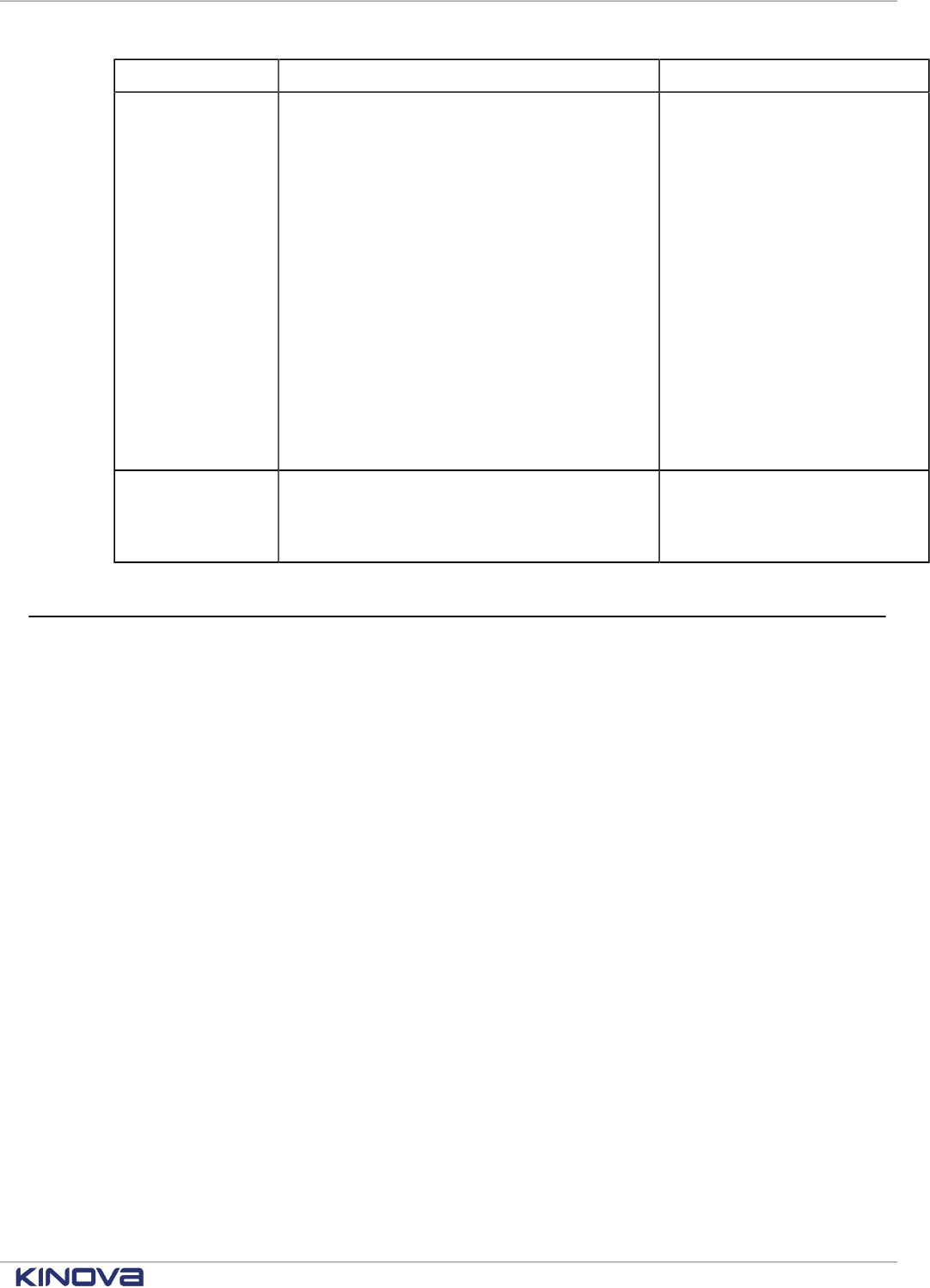
Kinova® Gen3 Ultra lightweight robot User Guide 119
Configurable item Description Where to configure it
Instrinsic
parameters
Set the intrinsic parameters for a chosen sensor:
• resolution
•
principal point - horizontal and vertical
coordinates of principal point of image,
as pixel offsets from left and top edge
respectively
•
focal length - horizontally and vertically
as multiple of pixel width and height
• distortion coefficients
º k1 - first radial distortion coefficient
º k2 - second radial distortion coefficient
º k3 - third radial distortion coefficient
º p1 - first tangential distortion coefficient
º p2 - second tangential distortion
coefficient
Kinova.Api.VisionConfig
API
Extrinsic
parameters
Set sensor extrinsic parameters:
• rotation matrix from depth to color sensor
• translation vector from depth to color sensor
Kinova.Api.VisionConfig
API
Safety items
There are a number of safety items related to different components of the robot. These are viewable in the
Web App Safeties page.
Overview
Safety items, and their associated warning and error thresholds are active on the robot and are
viewable and configurable within the Safeties page of the Web App. There are several categories of
safeties:
• Base (arm) safeties
• Actuators safeties
• Interface module safeties
The tables that follow give more information about the safeties, including:
• Description - significance of the safety item
• Hard limit (lower) - the minimum allowable value for the item
• Hard limit (upper) - the maximum allowable value for the item
• Default warning / error threshold - default configurations for the safety thresholds.
Base safeties
The following Base-related Safety items are viewable in the Web App.
+1 514-277-3777 kinovarobotics.com
© 2022 Kinova inc. All rights reserved.
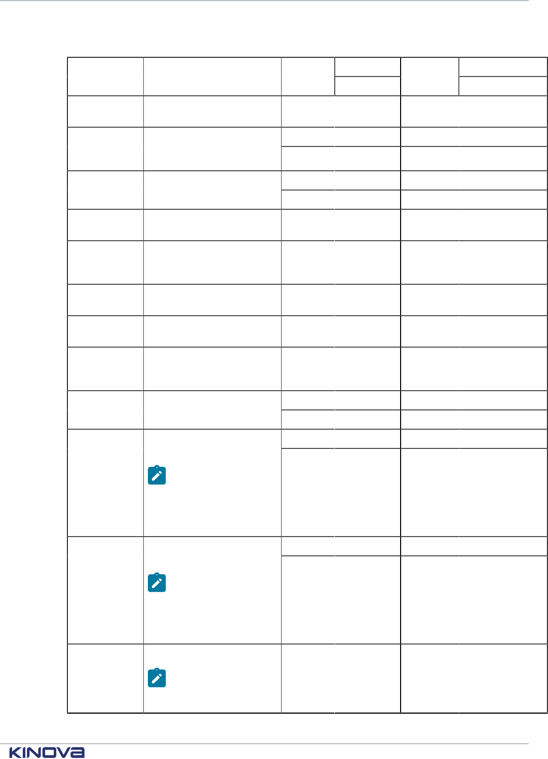
Kinova® Gen3 Ultra lightweight robot User Guide 120
Table 69: Base Safety items
lower warning
Safety Item Description Hard limit
upper
Default
threshold
error
Firmware
Update Failure
Indicates a failure in the
firmware update process.
n/a n/a
0.0 °C 70.0 °CMaximum
Ambient
Temperature
The ambient temperature is
above upper limit
90.0 °C 80.0 °C
0.0 °C 75.0 °C
Maximum Core
Temperature
The core temperature is
above upper limit
100.0 °C 85.0 °C
Joint Fault
At least one joint is in a fault
state
n/a n/a
Joint Detection
Error
The number of detected
joints does not match the
configured arm joint count.
n/a n/a
No kinematics
support
Current degree of freedom
configuration not supported
n/a n/a
Network error
Loss of actuator cyclic data
response
n/a n/a
Network
Initialization
Error
Arm is detected but control
bus link is down n/a n/a
0.0 A 9.0 A
Maximum
Current
The base current reading is
above upper limit
12.0 A 10.0 A
16.0 V 18.0 V
Minimum
Voltage
The base voltage reading is
below lower limit
Note: The
minimum voltage
must be lower
than the maximum
voltage
24.0 V 16.0 V
24.0 V 30.0 V
Maximum
Voltage
The base voltage reading is
above upper limit.
Note: The
maximum voltage
must be higher
than the minimum
voltage
31.0 V 31.0 V
Emergency
Stop Activated
Emergency stop activated.
Note: electronic
protection cannot
be deactivated
n/a n/a
+1 514-277-3777 kinovarobotics.com
© 2022 Kinova inc. All rights reserved.
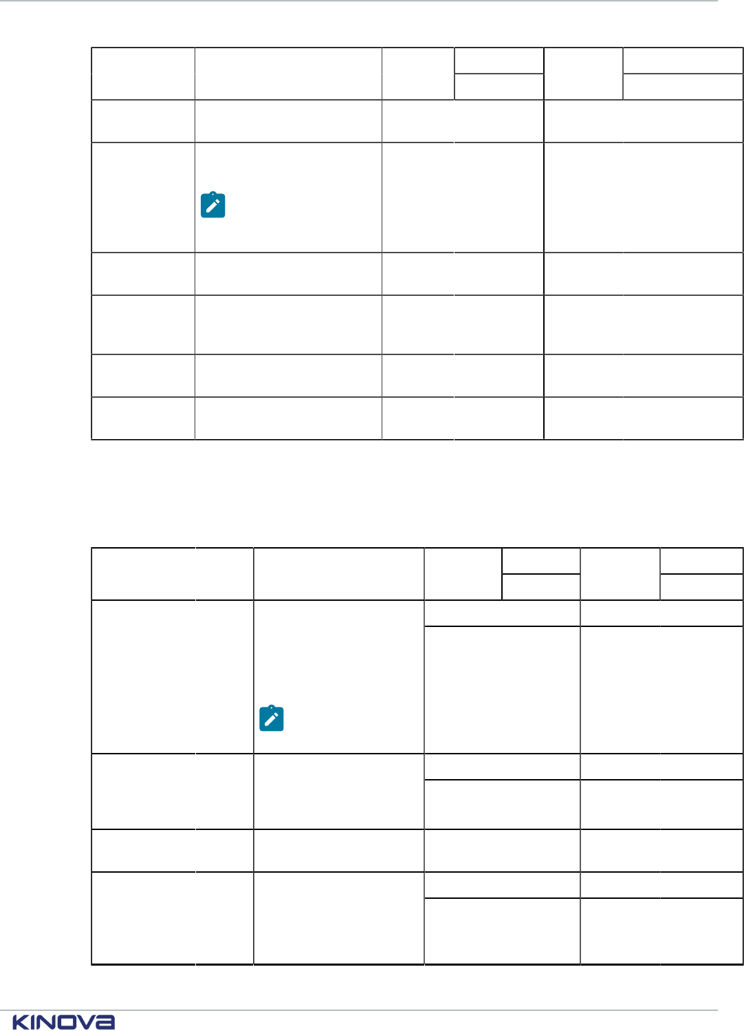
Kinova® Gen3 Ultra lightweight robot User Guide 121
lower warning
Safety Item Description Hard limit
upper
Default
threshold
error
Emergency
line activated
Emergency line activated
n/a n/a
Inrush Current
Limiter Fault
Inrush current limiter fault
triggered.
Note: electronic
protection cannot
be deactivated
n/a n/a
NVRAM
corrupted
Non-volatile memory corrupt
n/a n/a
Incompatible
firmware
version
Firmware incompatible with
hardware board revision n/a n/a
Power-on self
test failure
The robot failed a power-on
self test
n/a n/a
Discrete input
stuck active
Joystick Control indicator
(GPI) stuck
n/a n/a
Actuators safeties
The following actuator-related Safety items are viewable in the Web App.
Table 70: General actuator safety items (apply the same to all actuator sizes)
lower warning
Safety Item Description Hard limit
upper
Default
threshold
error
0° 3.0°
Following Error
The error between
the command and the
reported position is
above upper limit.
Note: Only
active when in
servoing state
10° 5.0°
0° 3.0°
Magnetic Position
Position step of more
than threshold °/ms has
been read on the magnetic
sensor.
20° 5.0°
Hall Sequence
Invalid Hall sequence
detected.
n/a n/a
0° 1.5°
Input Encoder
Hall Mismatch
The Hall sensor position
value doesn’t match the
input optical encoder
position within +/-
threshold degrees.
10° 2.0°
+1 514-277-3777 kinovarobotics.com
© 2022 Kinova inc. All rights reserved.
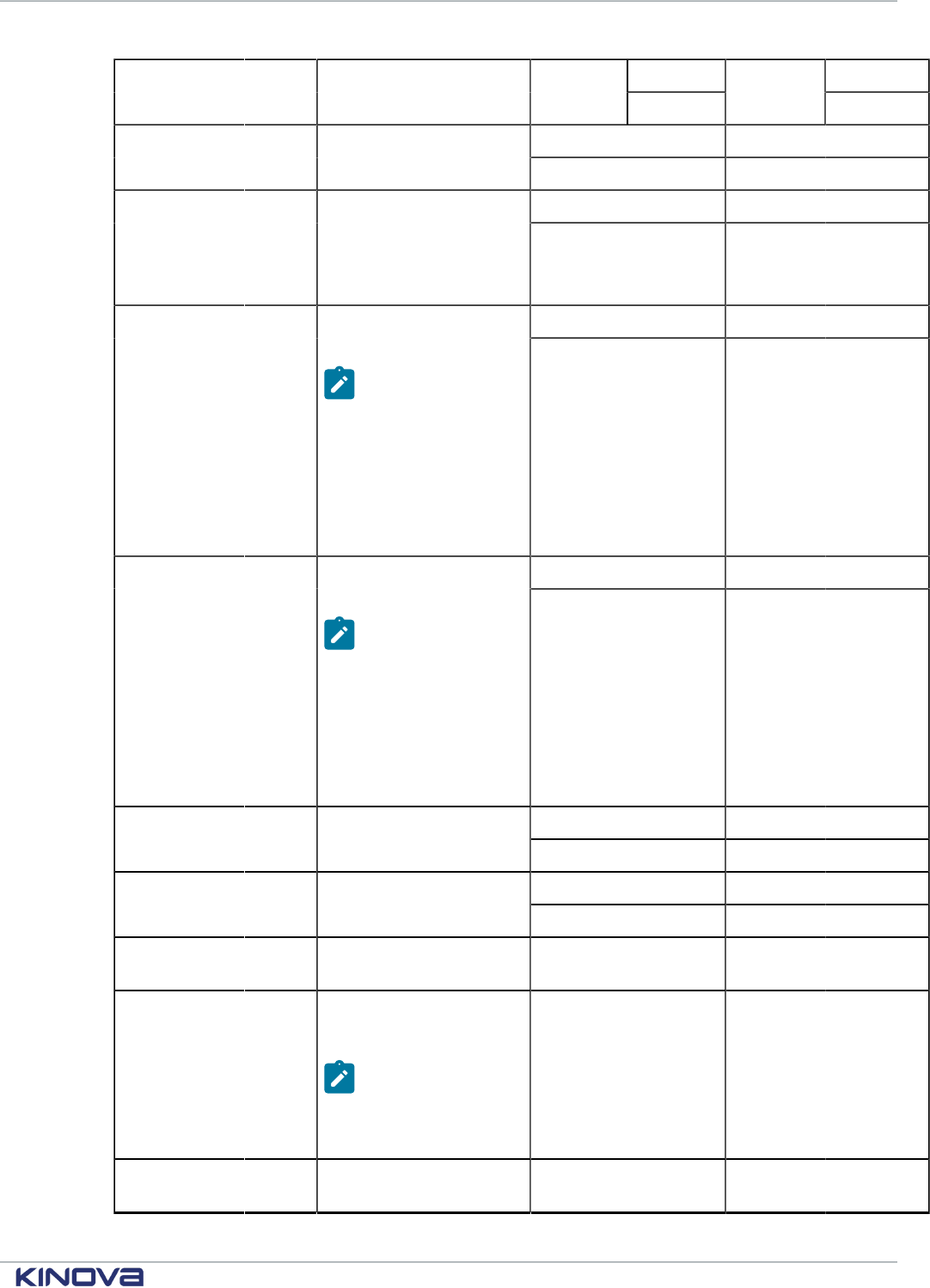
Kinova® Gen3 Ultra lightweight robot User Guide 122
lower warning
Safety Item Description Hard limit
upper
Default
threshold
error
0 500
Input Encoder
Index Mismatch
Input encoder index
position mismatch
2000 1000
0° 10°
Input Encoder
Magnetic Mismatch
The input optical encoder
position value doesn’t
match with the magnetic
encoder position within +/-
threshold degrees.
45° 15°
16.0 V 18.0 V
Minimum Voltage
The voltage reading is
below lower limit.
Note: The
minimum
voltage
thresholds must
be lower than
the maximum
voltage
thresholds.
24.0 V 16.0 V
24.0 V 30.0 V
Maximum Voltage
The voltage reading is
above upper limit.
Note: The
maximum
voltage
thresholds must
be higher than
the minimum
voltage
thresholds.
31.0 V 31.0 V
0.0 °C 60.0 °C
Maximum Motor
Temperature
Motor temp is above
upper limit
80.0 °C 75.0 °C
0.0 °C 80.0 °C
Maximum Core
Temperature
Core temp above upper
limit
100.0 °C 90.0 °C
Non-Volatile
Memory Corrupted
Non-volatile memory
corrupt
n/a n/a
Motor Driver Fault
Driver chip reported a
major fault
Note: electronic
protection
cannot be
deactivated
n/a n/a
Emergency Line Asserted
Emergency line asserted.
Motor drive disabled
n/a n/a
+1 514-277-3777 kinovarobotics.com
© 2022 Kinova inc. All rights reserved.
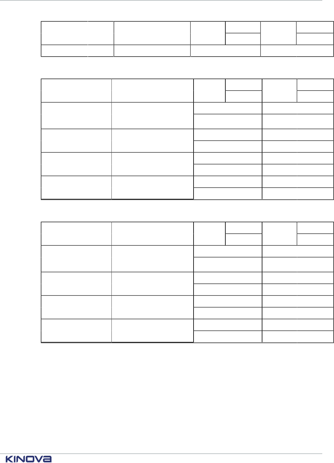
Kinova® Gen3 Ultra lightweight robot User Guide 123
lower warning
Safety Item Description Hard limit
upper
Default
threshold
error
Watchdog Triggered Watchdog was triggered n/a n/a
Table 71: Small actuator specific safeties
lower warningSafety Item Description Hard
limit
upper
Default
threshold
error
0 °/s 180 °/sMaximum Velocity The computed velocity
of the actuator is greater
than threshold °/sec.
250 °/s 200 °/s
0 N·m 29.4 N·mMaximum Torque Torque reading
higher than x N·m.
52 N·m 51.3 N·m
0° n/aHall Position Position step of more
than threshold °/ms
10° 0.4285°
0.0 A 6.0 AMaximum
Motor Current
The measured current of the
motor is above upper limit
8.0 A 7.0 A
Table 72: Large actuator specific safeties
lower warningSafety Item Description Hard
limit
upper
Default
threshold
error
0 °/s 100 °/sMaximum Velocity The computed velocity
of the actuator is greater
than threshold °/sec.
150 °/s 120 °/s
0 N·m 56.7 N·mMaximum Torque Torque reading
higher than x N·m.
105 N·m 104.5 N·m
0° n/aHall Position Position step of more
than threshold °/ms
10° 0.2145°
0.0 A 10.0 AMaximum
Motor Current
The measured current of the
motor is above upper limit
12.0 A 11.0 A
Interface module safeties
The following Interface module-related Safety items are viewable and configurable in the Web App.
+1 514-277-3777 kinovarobotics.com
© 2022 Kinova inc. All rights reserved.
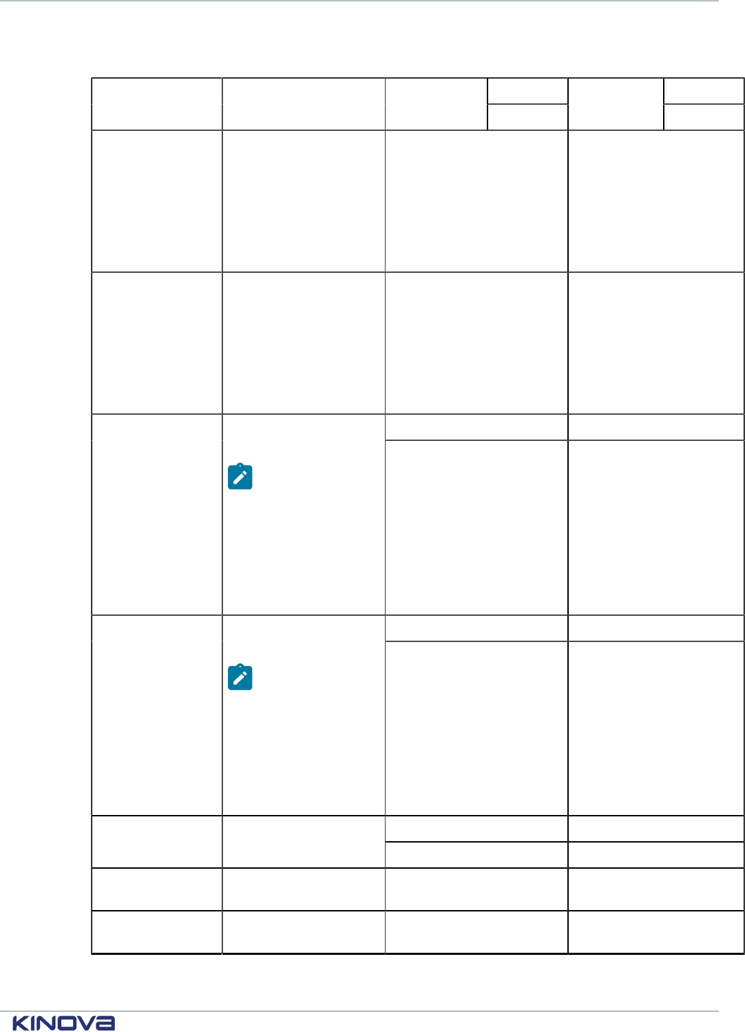
Kinova® Gen3 Ultra lightweight robot User Guide 124
Table 73: Interface Safety items
lower warningSafety Item Description Hard limit
upper
Default
threshold
error
Maximum
Motor Current
The measured motor
current in the connected
3rd party gripper (if
compatible gripper is
attached) is above the
higher limit. If gripper is
not present the safety is
disabled.
n/a n/a
Maximum Motor
Temperature
The motor temperature
of the connected
3rd party gripper (if
compatible gripper is
attached) is above the
higher limit. If gripper is
not present the safety is
disabled.
n/a n/a
16.0 V 18.0 VMinimum Voltage Voltage reading below
lower limit
Note:
minimum
voltage
thresholds
must be below
maximum
voltage
thresholds
24.0 V 16.0 V
24.0 V 30.0Maximum Voltage Voltage reading above
upper limit
Note:
maximum
voltage
thresholds
must be above
minimum
voltage
thresholds
31.0 V 31.0
0.0 °C 80.0 °CMaximum Core
Temperature
Core temperature above
upper limit
100.0 °C 90.0 °C
Non-Volatile
Memory Corrupted
Non-volatile memory
corrupt
n/a n/a
Emergency
Line Asserted
Emergency line asserted.
Motor drive disabled
n/a n/a
+1 514-277-3777 kinovarobotics.com
© 2022 Kinova inc. All rights reserved.
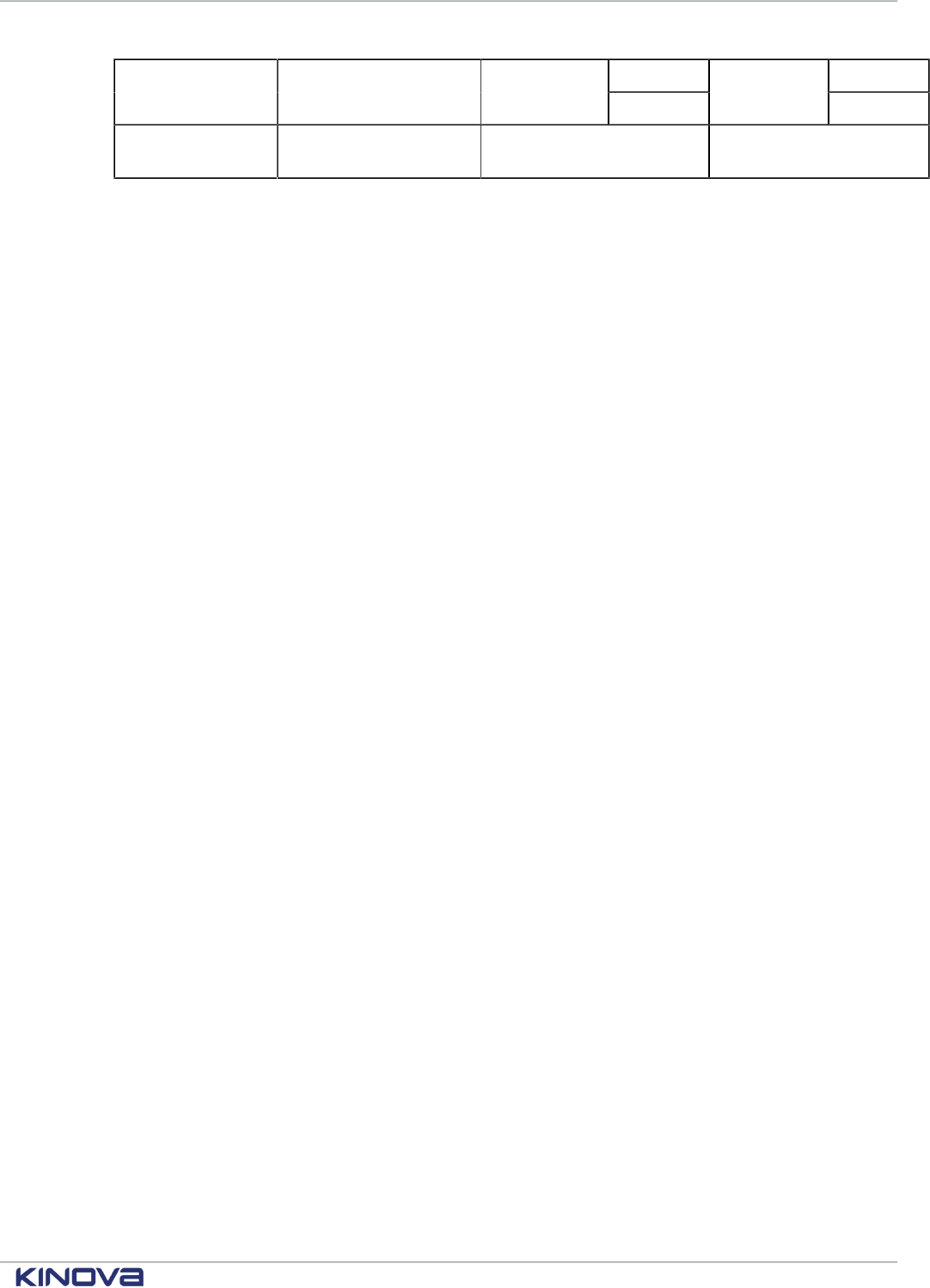
Kinova® Gen3 Ultra lightweight robot User Guide 125
lower warningSafety Item Description Hard limit
upper
Default
threshold
error
Watchdog
Triggered
Watchdog triggered
n/a n/a
+1 514-277-3777 kinovarobotics.com
© 2022 Kinova inc. All rights reserved.
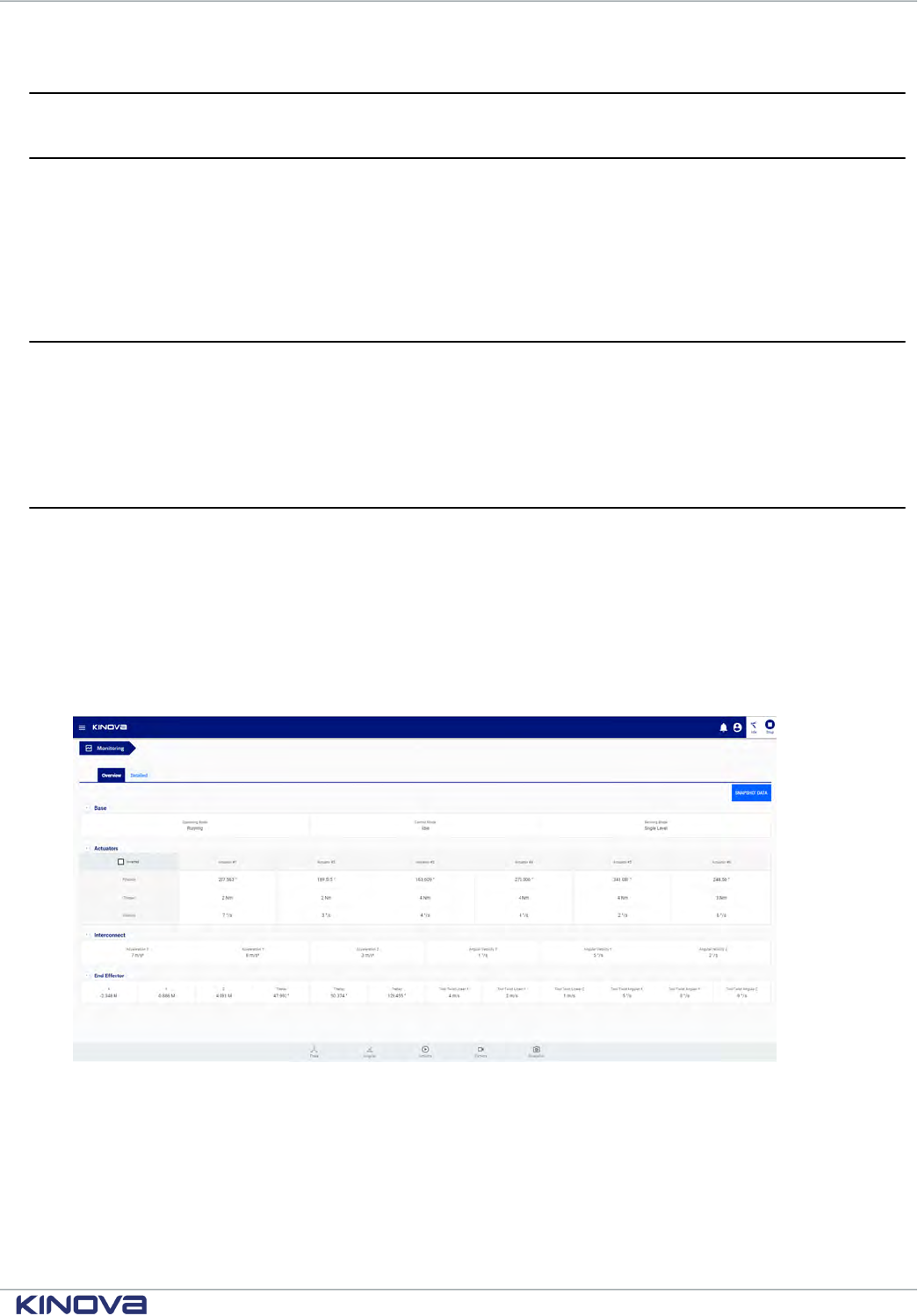
Kinova® Gen3 Ultra lightweight robot User Guide 126
Kinova® Kortex™ Web App User Guide
Introduction
Overview of the Web App section of the user guide.
The following sections describe the Kinova
®
Kortex™ Web App. The Web App is used for controlling,
configuring and monitoring the robot.
This pages that follow describe the purpose, layout, and use of the Web App.
Purpose
The Web App provides a convenient Web-based GUI for configuring, controlling, and monitoring the robot.
The Web App is a Web GUI (Graphical User Interface) that runs on the robot. This web interface
allows users to configure, control and monitor the robot through a web browser interface from a
computer connected to the robot over a wired Ethernet or Wi-Fi connection.
Device availability of Web App
The Web App is available on desktop computers, tablets, and smartphones.
The Web App is a responsive web application. It is designed to adapt itself to various aspect ratios
and resolutions enabling it to run on multiple platforms that support the Google Chrome browser.
This includes:
• desktop / laptop computer
• tablet computer
• smartphone
Figure 42: Desktop
+1 514-277-3777 kinovarobotics.com
© 2022 Kinova inc. All rights reserved.
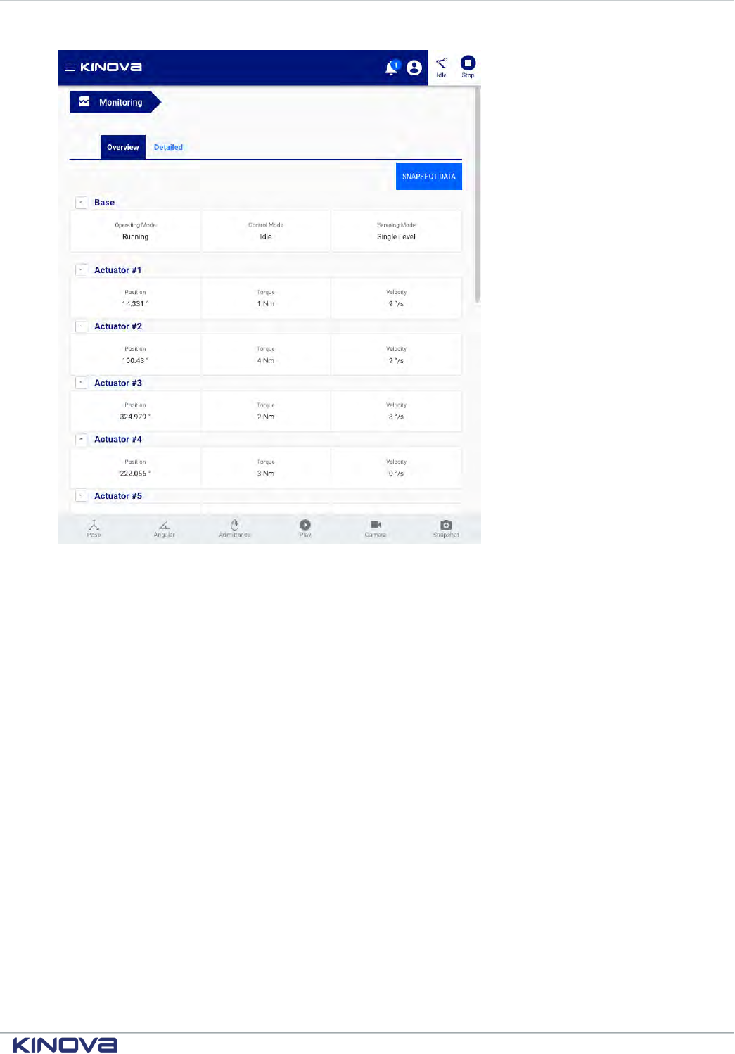
Kinova® Gen3 Ultra lightweight robot User Guide 127
Figure 43: Tablet
+1 514-277-3777 kinovarobotics.com
© 2022 Kinova inc. All rights reserved.
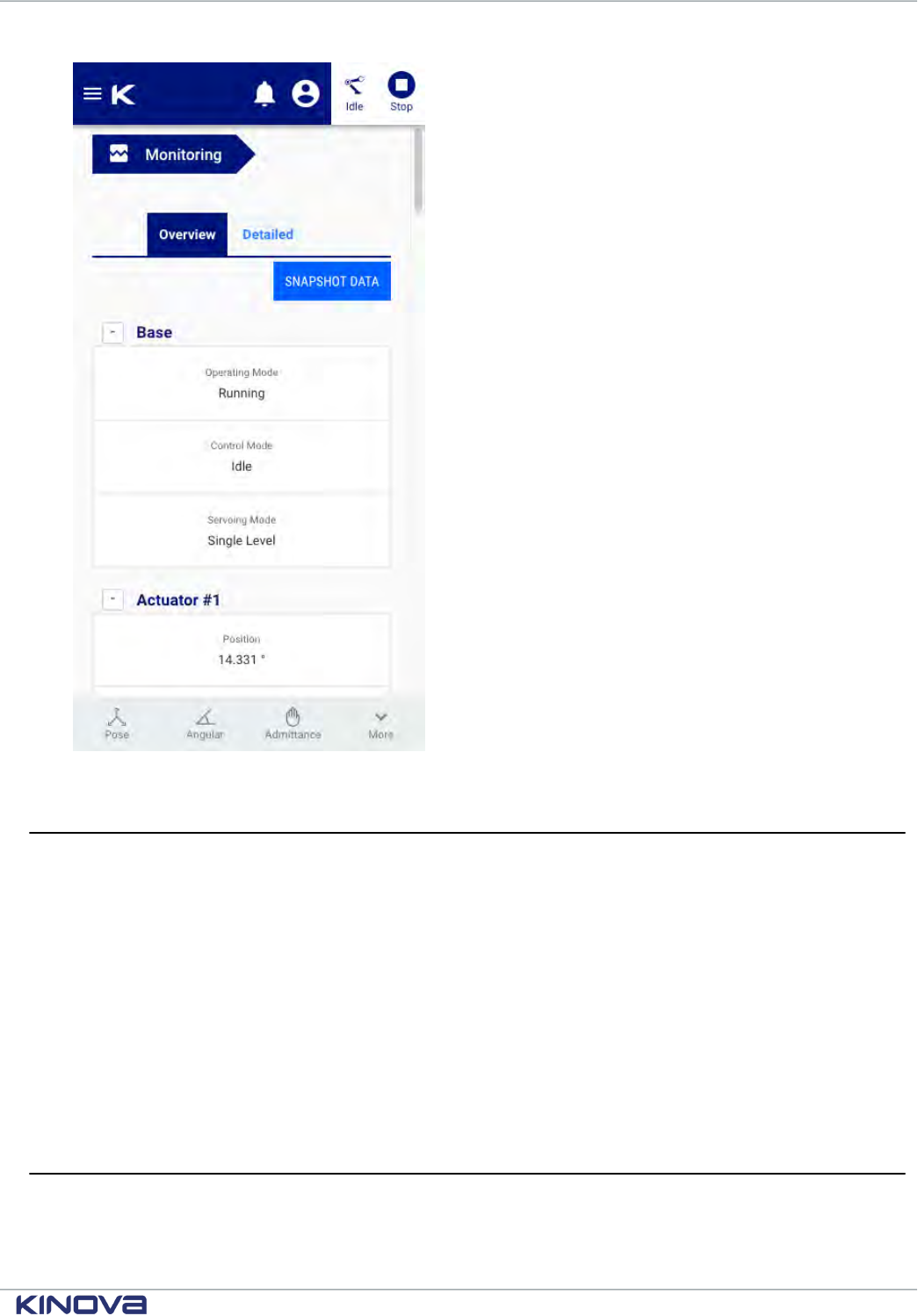
Kinova® Gen3 Ultra lightweight robot User Guide 128
Figure 44: Smartphone
Platform and browser support
This section describes platform and browser support for the Web App.
The Web App has the following platform and browser support.
Operating system support
• Microsoft Windows 7/8/10
• Ubuntu LTS 16.04
• Android 8.1 and higher
Browser support
• Chrome
Other platforms and browsers are not tested; some features may work differently in those cases.
User login
Given the robot base IP address and a computer connected to the robot, users can log in to the Web App with
username and password via a Web browser.
+1 514-277-3777 kinovarobotics.com
© 2022 Kinova inc. All rights reserved.
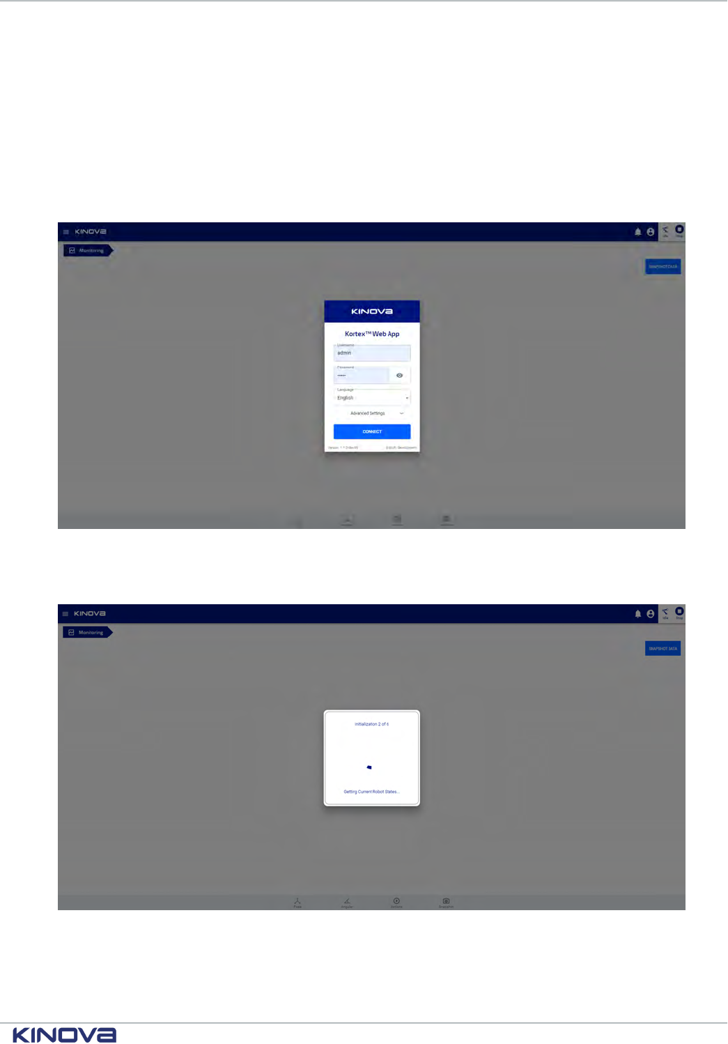
Kinova® Gen3 Ultra lightweight robot User Guide 129
After establishing a network connection between your device and the robot, open a web browser
and enter the IP address for the robot base external interface.
The Web App will launch, ending in a login popup.
Enter your username and password and press the CONNECT button.
The default username and password for the robot are:
• username: admin
• password: admin
Figure 45: User login
On pressing CONNECT, the Web App will launch and initialize. While it is doing this, the Web App
will give visual feedback to the user on the status of initialization of the application.
Figure 46: Initializing...
+1 514-277-3777 kinovarobotics.com
© 2022 Kinova inc. All rights reserved.
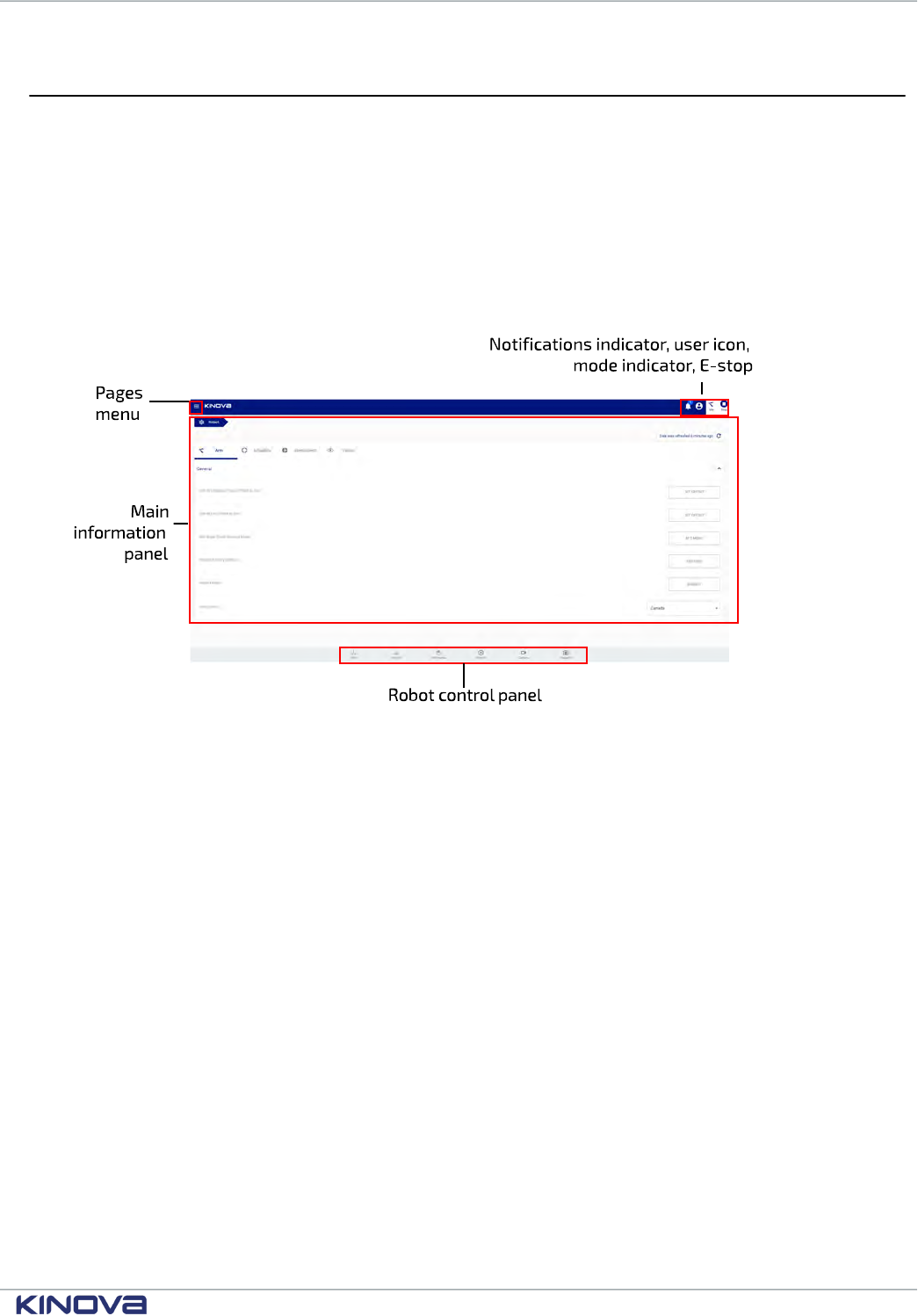
Kinova® Gen3 Ultra lightweight robot User Guide 130
Web App layout and navigation
This section describes the basic layout and navigation of the Web App.
The Web App screen is divided into several main sections:
• Main navigation panel
• Main information panel
• Notification bar
• Shortcuts panel
• Robot control panel
• Mode indicator, user icon, and E-stop
Figure 47: Web App Layout
Pages menu
In the middle of the screen is the main information panel containing the contents of each page of
the application. The page can be changed from a pages menu on the left of the screen. This menu is
hidden by default, but can be lauched by clicking / tapping the menu icon in the upper left.
+1 514-277-3777 kinovarobotics.com
© 2022 Kinova inc. All rights reserved.
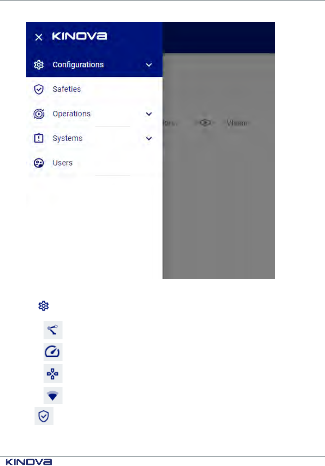
Kinova® Gen3 Ultra lightweight robot User Guide 131
The page options are organized into groups:
•
Configurations
º
Robot
º
Speed Limits
º
Controllers
º
Wireless & Networks
•
Safeties
+1 514-277-3777 kinovarobotics.com
© 2022 Kinova inc. All rights reserved.

Kinova® Gen3 Ultra lightweight robot User Guide 132
•
Operations
º
Actions
º
Protection Zones
º
Camera
•
Systems
º
System Information
º
Monitoring
º
Upgrade
•
Users
In the upper right hand corner of the screen are four indicators/controls:
•
Notifications indicator - number of most important notifications. Clicking allows
notifications to be read.
•
User profile icon - Shows the user session icon
+1 514-277-3777 kinovarobotics.com
© 2022 Kinova inc. All rights reserved.
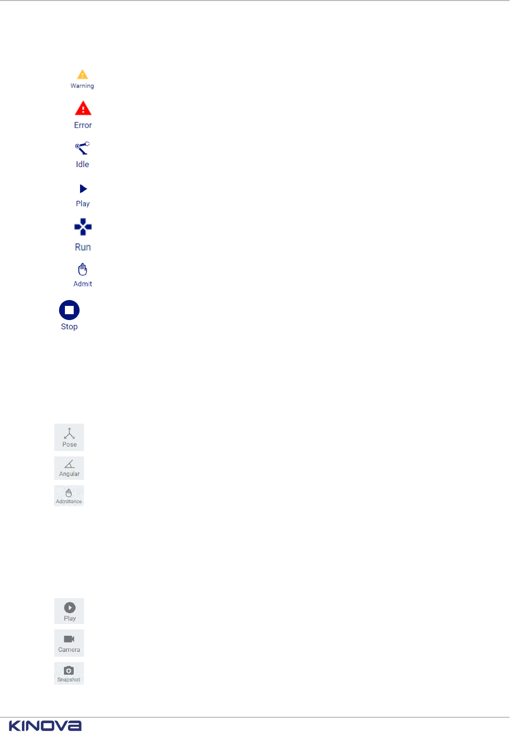
Kinova® Gen3 Ultra lightweight robot User Guide 133
• Control mode - status of the control mode situation of the robot. There are four icons to indicate
the mode / state:
º
Warning - robot in warning state
º
Error - robot is in a fault state
º
Idle - robot is not currently being controlled by any user session; waiting
º
Playing - a sequence is being played on the robot
º
Running - the robot is being actively controlled by a user
º
Admittance - robot is being controlled in an admittance mode
•
Emergency Stop (E-stop) - button control which when pressed/tapped will initiate the
emergency stop of the robot.
Clicking on any of these items displays a pop-up showing further information.
Robot control panel
The control panel is on the bottom of the screen, and consists of a group of six buttons. Three are to
launch pop-up windows for virtual joystick controls and admittance mode toggles:
•
Pose Virtual Joystick
•
Angular mode control
•
Admittance controls
The virtual joysticks allow you to control the movement of the robot without the use of a physical
controller.
Admittance mode lets you to move the robot with your hands in one of three (Cartesian, joint, and
null space) admittance modes.
In the same area there are three other controls:
•
Play action - brings up a window to play a selected action
•
Camera feed - brings up a window to view camera feed
•
Snapshot - allows user to capture a Cartesian, angular, or gripper pose
+1 514-277-3777 kinovarobotics.com
© 2022 Kinova inc. All rights reserved.
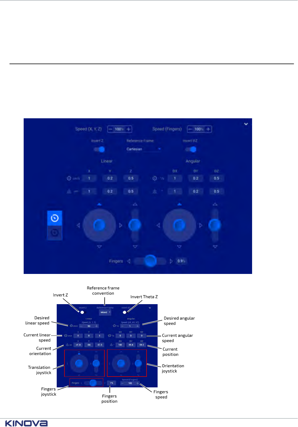
Kinova® Gen3 Ultra lightweight robot User Guide 134
Clicking on one of the buttons in the robot control panel will launch a smaller window from the
bottom of the screen, revealing the selected control panel.
Clicking the same button again will clear the smaller window at the bottom.
Robot control panel
Pose virtual joystick control
The Pose virtual joystick provides an interface to control Cartesian movement of the robot from the Web App.
The Pose virtual joystick panel allows users to control the position and orientation of the end
effector through the Web App using a mouse (on laptop or desktop computer) or touch control (on a
tablet or smartphone).
Figure 48: Pose joystick panel
+1 514-277-3777 kinovarobotics.com
© 2022 Kinova inc. All rights reserved.

Kinova® Gen3 Ultra lightweight robot User Guide 135
Figure 49: Pose joystick panel
The Pose virtual joystick panel is launched by clicking the first button ( ) on the robot control
panel.
Translation / rotation joystick controls
The Pose virtual joystick controls allow you to control the linear and angular motion of the tool.
There are two sets of joysticks:
• linear (to apply a translational motion to the end effector)
• angular (to apply a rotational motion to the end effector at the current position)
Each set of joysticks features a 2-axis joystick for controlling the x and y axes, and a 1-axis joystick
to control in the z-axis. For the 2-axis linear joystick, the user can configure the joystick axis that is
assigned to control the y direction movement.
The desired linear and angular speeds for the motion can also be configured here.
Note: The desired speeds must be less than the defaults for Cartesian twist speeds, or, if set,
the general or mode-specific Cartesian speed limits configured on the Speed Limits page.
As the controls are moved, a display is provided for the current position (x, y, z) and orientation (θ
x
,
θ
y
, θ
z
) of the end effector.
Note: The orientation representation uses an x-y-z extrinsic convention.
Finger controls
It is possible to open and close the fingers using a single 1-axis joystick control (if a gripper is
installed). Push the control up to open the fingers and down to close. The fingers position can be
controlled between 0% (fully closed) and 100% (fully open).
Velocity control
The robot can be controlled in velocity control.
Additional settings
By clicking the caret icon on the upper right-hand side, additional controls and displays are
revealed.
• current linear and angular velocity display
• invert z and θ
z
toggles
• reference frame selection
• gripper speed control
• speed limit
Speed control
The actuators speed and finger speed can be adjusted between 0 and 100% of the hard limits for
the robot.
Reference frames
The position of the end effector can be specified in one of three reference frame conventions:
• Mixed - linear in base reference frame, angular in tool reference frame
• Base - linear and angular in base reference frame
+1 514-277-3777 kinovarobotics.com
© 2022 Kinova inc. All rights reserved.
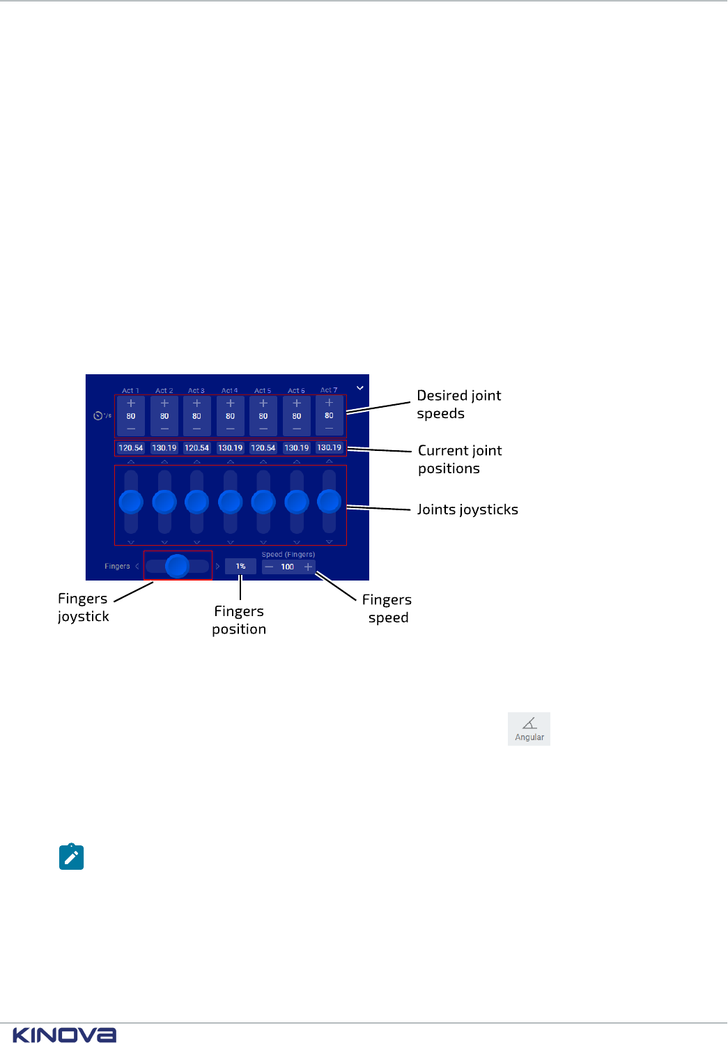
Kinova® Gen3 Ultra lightweight robot User Guide 136
• Tool - linear and angular in tool reference frame
The tool reference frame convention is useful when controlling the robot using visual feedback
from the camera sensors. The joystick will control movement of the end effector with respect to the
tool reference frame, which is parallel to the reference frame of the camera. This makes it easy to
command the robot in relation to what is seen through the camera.
Z and θ
z
toggles
The default for the 1-axis z-direction controls is that 'up' increases the z-position or z-angle, while
'down' decreases it. This can be reversed using the Invert Z and Invert θ
z
toggles.
Angular virtual joystick control
The Angular virtual joystick provides an interface to control the join by joint movement of the robot from the
Web App.
The angular virtual joystick panel allows users to control the robot joint angles and gripper
fingers (if gripper installed) through the Web App using a mouse (or touch control on a tablet or
smartphone).
Figure 50: Angular virtual joystick panel
The joint angles are controlled through angular velocity (controlling the joint speed for each
actuator)
The angular joystick panel is launched by clicking the second button on the robot control
panel.
The virtual joystick controls allow you to control the angle of each actuator as well as the opening
and closing of the fingers (if a gripper is installed). As the virtual joystick controls are manipulated,
the robot arm joints respond accordingly.
Note: For joints with joint rotation limits, the robot enforces software joint angle limits to
prevent these joints from reaching the physical limits. When you control these joints, the
software will cause the arm joints to stop responding when the limits are reached.
The value of each angle is displayed in degrees. The value displayed is restricted to one full rotation
(0 - 360°).
Additional settings
+1 514-277-3777 kinovarobotics.com
© 2022 Kinova inc. All rights reserved.
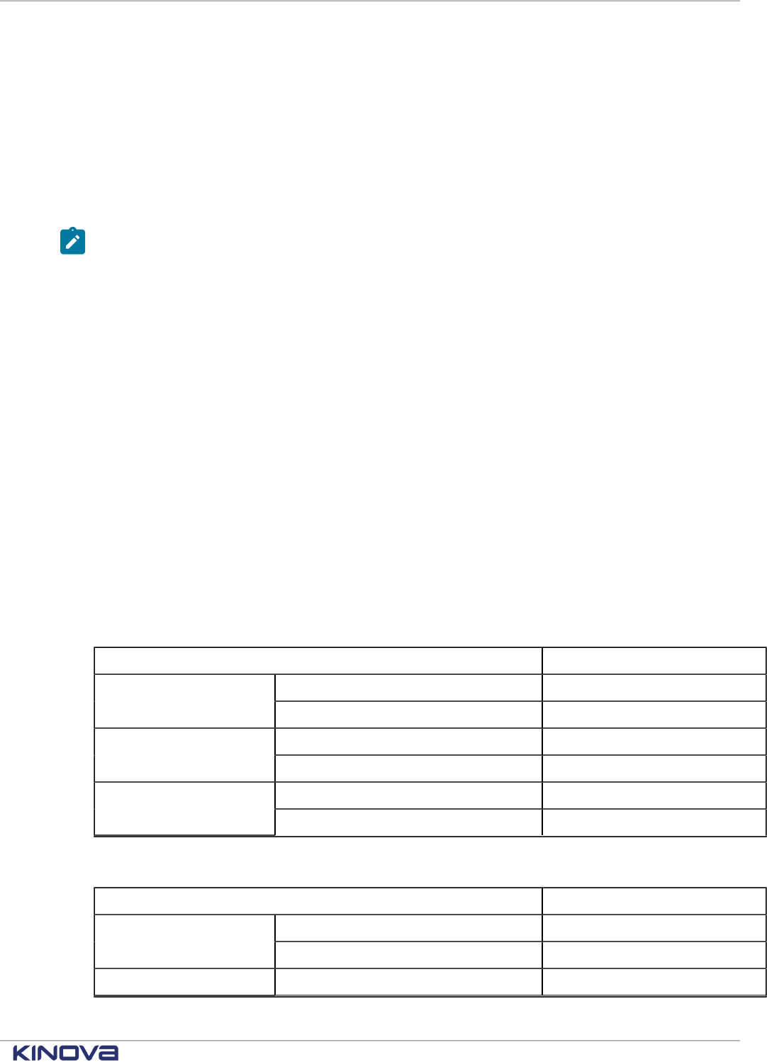
Kinova® Gen3 Ultra lightweight robot User Guide 137
By clicking the caret icon on the right-hand side, additional controls are revealed. These let the user
control the maximum actuators and finger speed, between 0 and 100% of maximums.
To control the angle of each actuator, use the virtual joystick controls to apply a velocity in the given
direction. Pushing the joystick up causes the angle to increase, while pushing it down causes it to
decrease. The further up or down the joystick is pushed, the higher the angular speed for the joint,
up to the set limit. The angle will continue to change as long as the joystick is being pushed.
The desired joint speeds for each joint can also be configured here. This controls the speed at which
the joints will move to produce the movement.
Note: The desired joint speeds must be less than the defaults for joint speeds, or, if set, the
general or mode-specific joint speed limits configured on the Speed Limits page.
Another joystick allows users to control the end effector finger position (if an end effector is
installed). The values for the finger state range between 0% (fully closed) and 100% (fully open).
Push the joystick to the right to increase the percentage (and open the fingers). Push the joystick to
the left to decrease the percentage (and close the fingers).
Virtual joystick keyboard shortcuts
Keyboard shortcuts are available for Web App virtual joysticks when accessing the Web App from a desktop
device with keyboard. This serves as an alternate to mouse and touch for controlling the robot via the virtual
joysticks.
Introduction
The virtual joysticks for the Web App are controllable with mouse or touch inputs. Some people
(particularly those with a background in PC gaming) may find it more natural to control using
keyboard shortcuts. If you are accessing the Web App using a desktop device that has a keyboard
(such as a desktop or laptop PC) there are handy keyboard shortcuts available for the joystick
controls.
Cartesian joysticks keyboard shortcuts
Table 74: Pose translation joystick shortcuts
Control Shortcut
+ W
X translation
- S
+ A
Y translation
- D
+ Q
Z translation
- E
Table 75: Pose orientation joystick shortcuts
Control Shortcut key
+ I
X rotation
- K
Y rotation + L
+1 514-277-3777 kinovarobotics.com
© 2022 Kinova inc. All rights reserved.
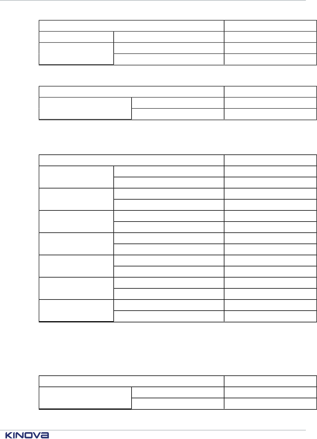
Kinova® Gen3 Ultra lightweight robot User Guide 138
Control Shortcut key
- J
+ U
Z rotation
- O
Table 76: Gripper controls (if gripper installed)
Control Shortcut key
open gripper fingers C
Gripper fingers
close gripper fingers V
Angular joystick keyboard shortcuts
Table 77: Actuators controls
Control Shortcut key
+ 1
Actuator 1 angle
- Q
+ 2
Actuator 2 angle
- W
+ 3
Actuator 3 angle
- E
+ 4
Actuator 4 angle
- R
+ 5
Actuator 5 angle
- T
+ 6
Actuator 6 angle
- Y
+ 7
Actuator 7 angle
- U
Put another way, the angles for joints 1-7 can be increased using the keys 1-7 on the top row of the
keyboard.
The angles can be decreased using the letter keys QWERTYU on the second row of the keyboard.
Table 78: Gripper controls (if gripper installed)
Control Shortcut
open gripper fingers C
Gripper fingers
close gripper fingers V
+1 514-277-3777 kinovarobotics.com
© 2022 Kinova inc. All rights reserved.
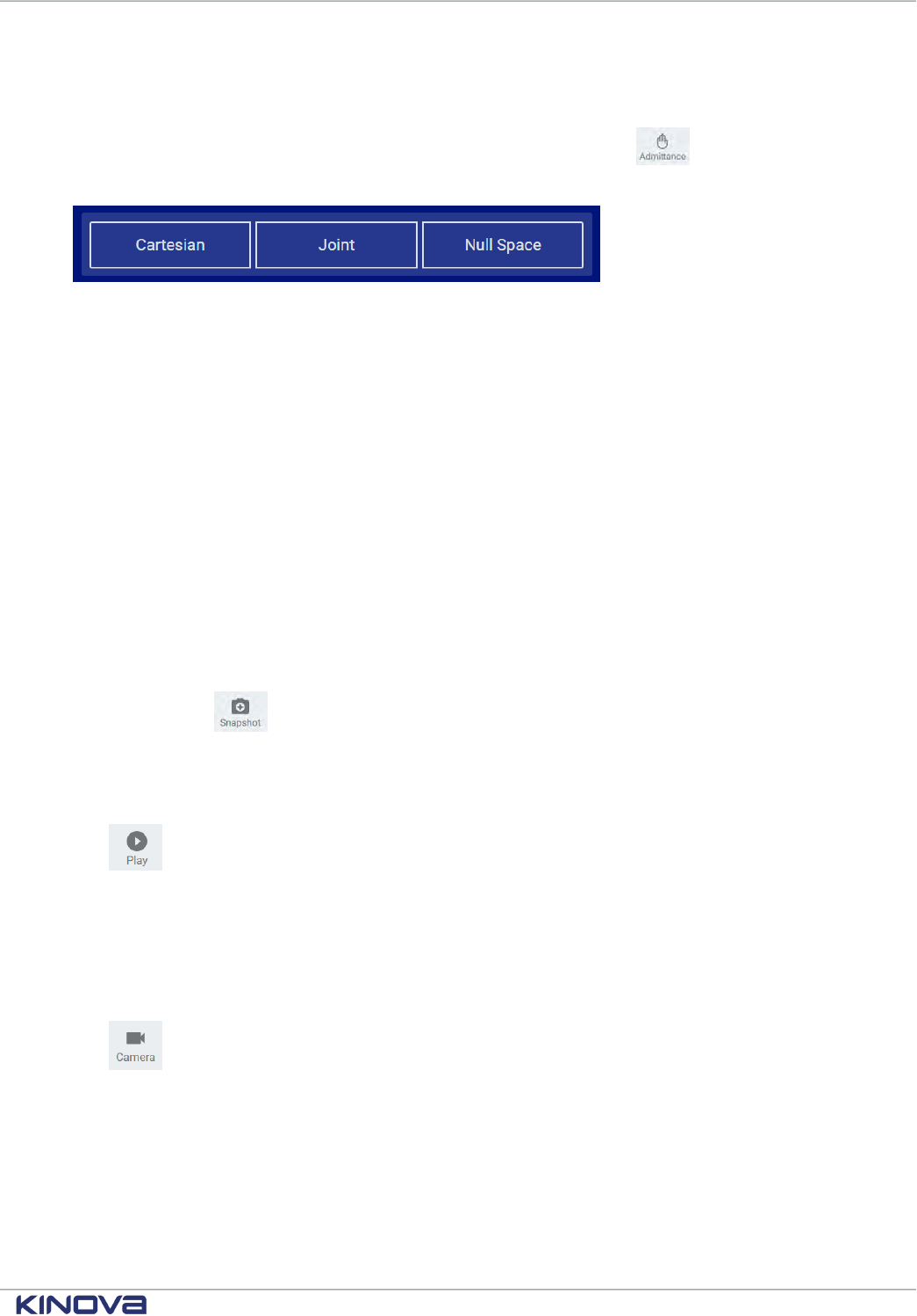
Kinova® Gen3 Ultra lightweight robot User Guide 139
Admittance modes panel
The admittance mode panel of the Web App allows users to set the robot into admittance modes.
The Admittance Mode panel is brought up by clicking the hand icon in the robot control
panel. The panel slides up from the bottom of the screen.
Figure 51: Admittance modes panel
An admittance mode is one in which the control systems of the robot take into account external
force / torque feedback from its environment.
From this panel, the arm can be set into one of three types of admittance mode:
• Cartesian admittance mode - tool moves according to the wrench (force + torque) applied on the
robot
• Joint admittance mode - joints of the robot rotate according to the external torques applied at
the joint
• Null Space admittance mode - end effector stays in the same position while the user manipulates
the joints of the robot within the null space. The robot moves within the null space according to
the external torques applied. Available only for legacy 7DoF robots.
It is also possible to take advantage of the admittance mode to manually move the robot into a
position and then capture a snapshot for future reference (normally, when not in an admittance
mode, the joints will resist being manipulated by external forces / torques).
While in admittance mode it is possible to record a Cartesian or Angular position by clicking the
snapshot button in the robot control panel.
Actions panel
The Actions panel of the Web App gives a control panel for the currently selected Action or Sequence.
The Actions panel provides controls to play, stop, or loop a selected Action.
The panel pops up from the bottom of the screen when an Action is selected in the Actions page.
Clicking the control panel Actions icon will toggle the visibility of the panel.
Camera panel
The Web App camera panel shows the live color sensor feed from the robot vision module within the Web App.
The Camera panel streams the live feed from the Web App color sensor in a pane at the
bottom of the Web App screen. This lets you have visual feedback from the perspective of the end
of the robot while controlling the robot movement.
Snapshot tool
The snapshot tool in the Web App captures and saves one of three types of instantaneous snapshots of the
robot / gripper positioning.
+1 514-277-3777 kinovarobotics.com
© 2022 Kinova inc. All rights reserved.
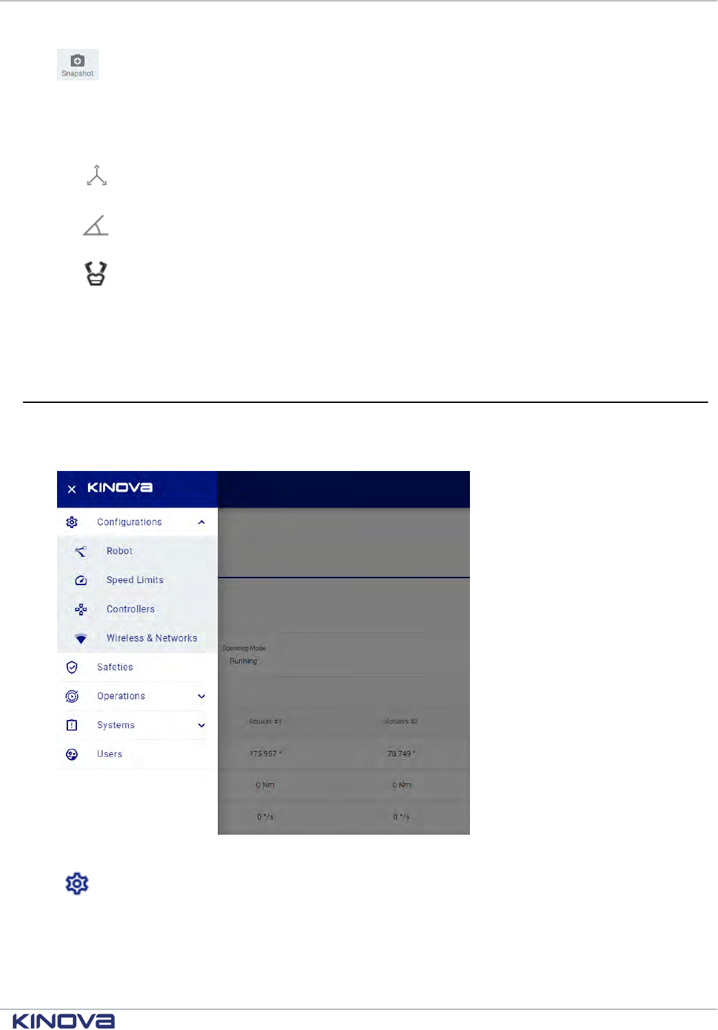
Kinova® Gen3 Ultra lightweight robot User Guide 140
The snapshot tool lets users capture a snapshot of a current position. This is a useful
feature to help with building pre-set sequences (for demos or to capture / program a fixed set of
movements).
Pressing the snapshot button reveals a set of three snapshot options:
•
Cartesian pose
•
Joints position
•
Gripper position
Pressing one of the respective snapshot buttons will capture the chosen type of snapshot of the
current robot position. This will be saved, and will show up as one of the saved Actions viewable in
the Actions page.
Main pages
Configurations page group
The Configurations page group of the Web App includes several pages useful for robot configuration.
Figure 52: Configurations page group
The Configurations page group contains pages allowing users to perform preliminary set up
and configuration for robot hardware.
This includes the following pages:
+1 514-277-3777 kinovarobotics.com
© 2022 Kinova inc. All rights reserved.
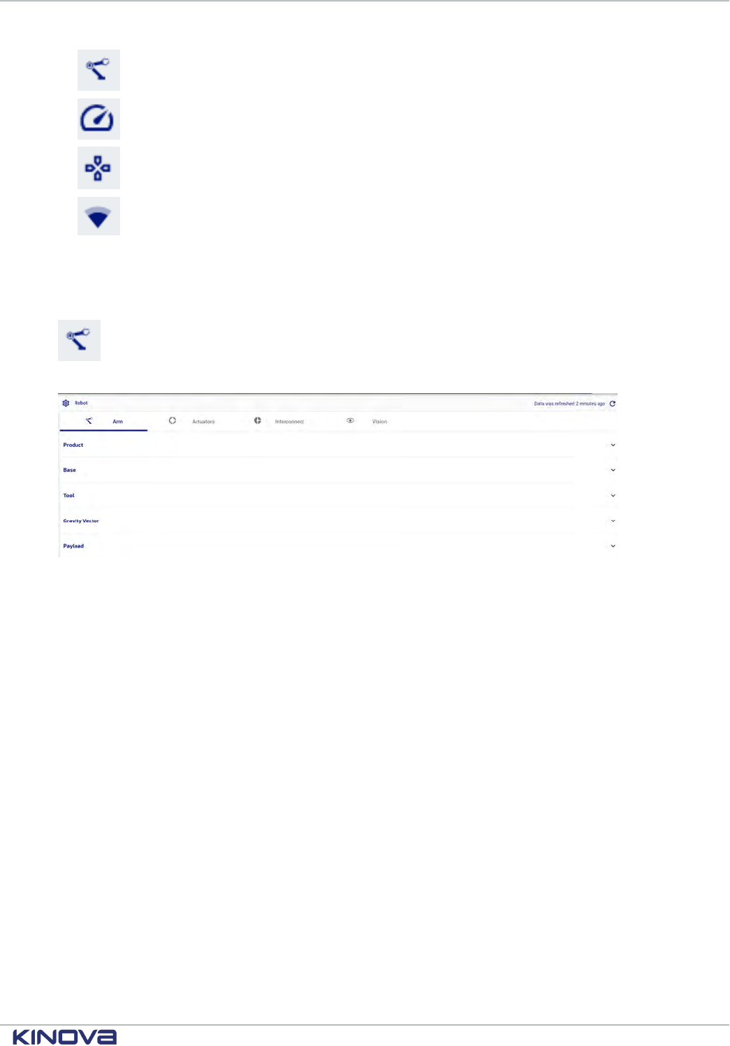
Kinova® Gen3 Ultra lightweight robot User Guide 141
•
Robot
•
Speed Limits
•
Controllers
•
Wireless & Networks
Robot configurations
The Robot configurations page of the Web App allows for the configuration of a broad range of robot
parameters.
The Robot configurations page provides a GUI to adjust the configurable parameters of the
robot hardware in order to customize its behavior.
Figure 53: Robot configurations page
The configurable items are broken into sections by devices:
• Arm
• Actuators
• Interconnect (interface module)
• Vision
Some configurable parameters of the robot can be configured on this page. Some other configurable
items are handled on their own pages:
• Protection Zones
• Controllers (switch active control mapping)
• Actions (define actions)
• Users (edit user profiles)
• Wireless & Networks (update network settings)
For more information on configurable parameters, refer to the section on Configurable parameters.
Speed Limits
The Speed Limits page of the Web App is used to set various soft limits for the robot, both globally, and by
control mode.
+1 514-277-3777 kinovarobotics.com
© 2022 Kinova inc. All rights reserved.
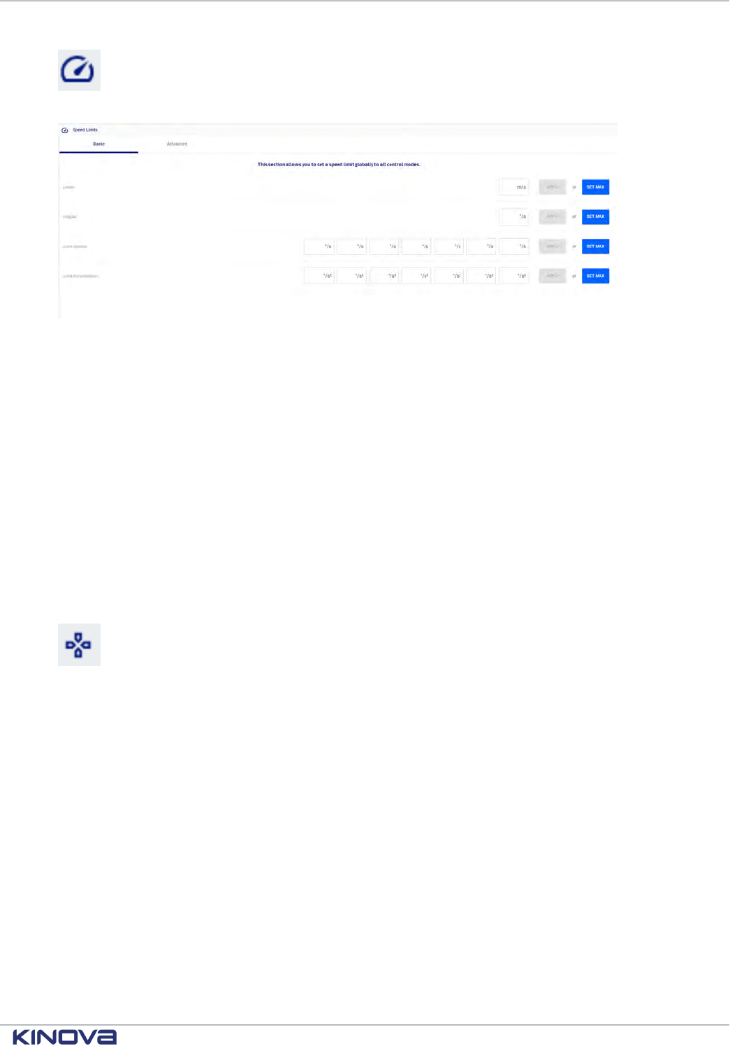
Kinova® Gen3 Ultra lightweight robot User Guide 142
The Speed Limits page provides a GUI to configure various soft speed limits for the robot, in
line with options available via the Kinova.Api.ControlConfig API.
Figure 54: Speed Limits page
The page contains two tabs:
• Basic
• Advanced
The Basic tab allows for setting speed limits globally for all control modes:
• Linear speed and angular speed for the tool (Cartesian)
• Joint speeds and accelerations (for each joint)
The Advanced tab allows for setting joint speed and acceleration limits for specific control modes.
The particular limits configurable under advanced will depend on the mode chosen.
For any setting, you can either set a specific value or set the value to the maximum.
Controllers
The Controllers page of the Web App lets users view, select, and create control mappings for the robot..
The Controllers page lets you view and toggle between the defined control mappings for any
physical control devices associated with the robot.
It also lets you define new control mappings and maps for recognized control devices.
A mapping for a control device is a set of maps, where each map represents one correspondence
between the different controls on the control device and the resulting actions produced on the
robot.
Each map consists of a number of map elements, which represent the combination of a single
control input and the function (action) it produces.
The page gives access to control mappings for control devices with predefined default mappings
like the Xbox gamepad and the wrist buttons on the interface module.
Once mappings and maps are defined via the Web App they can be activated in the Web App just as
with default maps.
+1 514-277-3777 kinovarobotics.com
© 2022 Kinova inc. All rights reserved.
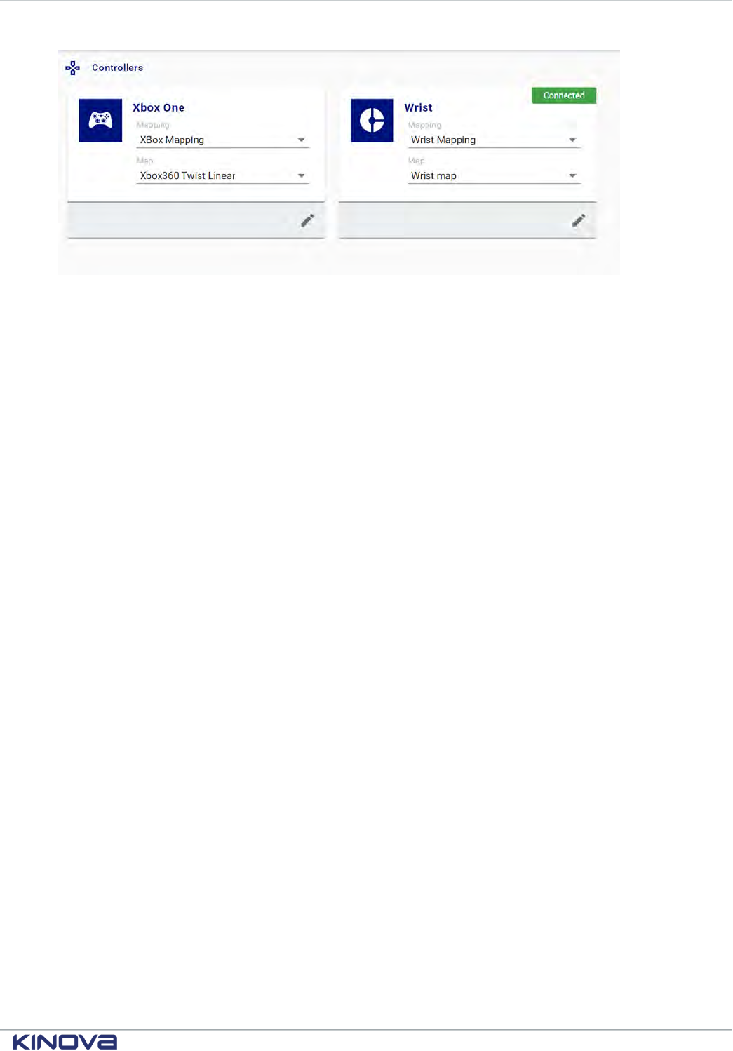
Kinova® Gen3 Ultra lightweight robot User Guide 143
Figure 55: Controllers page
The main information panel of the Controllers page has cards for each recognized control device.
On each control device card you can:
• view defined control mappings for the device and activate one of the mappings
• view defined control maps for each mapping and activate one of the mappings
• open the mappings editor for the control device
On each card, the currently selected mapping and map are shown. Control devices that are
currently connected appear with a green "Connected" icon in the upper right hand corner.
The following cards are shown by default:
• Xbox
• Wrist
• GPIO
The Xbox card is for a generic Xbox gamepad. By default, it has one mapping, Xbox Mapping. This
mapping has three preset control maps which correspond to the maps that can be toggled using the
physical buttons on the gamepad:
• Xbox Twist Linear
• Xbox Twist Angular
• Xbox Joint
The Wrist card is for mapping the two buttons on the wrist of the robot arm. By default, it has
one mapping, Wrist Mapping. This mapping is for the two buttons on the wrist of the robot. This
mapping has two preset control maps:
• Wrist map
• Wrist teaching gripper
Mappings editor
The control device mapping editor in the Web App Controllers page allows users to define new control
mappings for a control device.
On the Web App Controllers page main screen, clicking the edit button on a control device card
opens the mappings editor for the device.
In the mappings editor, you can view and modify mappings for a control device. This includes:
• creating a new mapping
• adding a new map to a mapping
• adding new functions controllable by a map
+1 514-277-3777 kinovarobotics.com
© 2022 Kinova inc. All rights reserved.
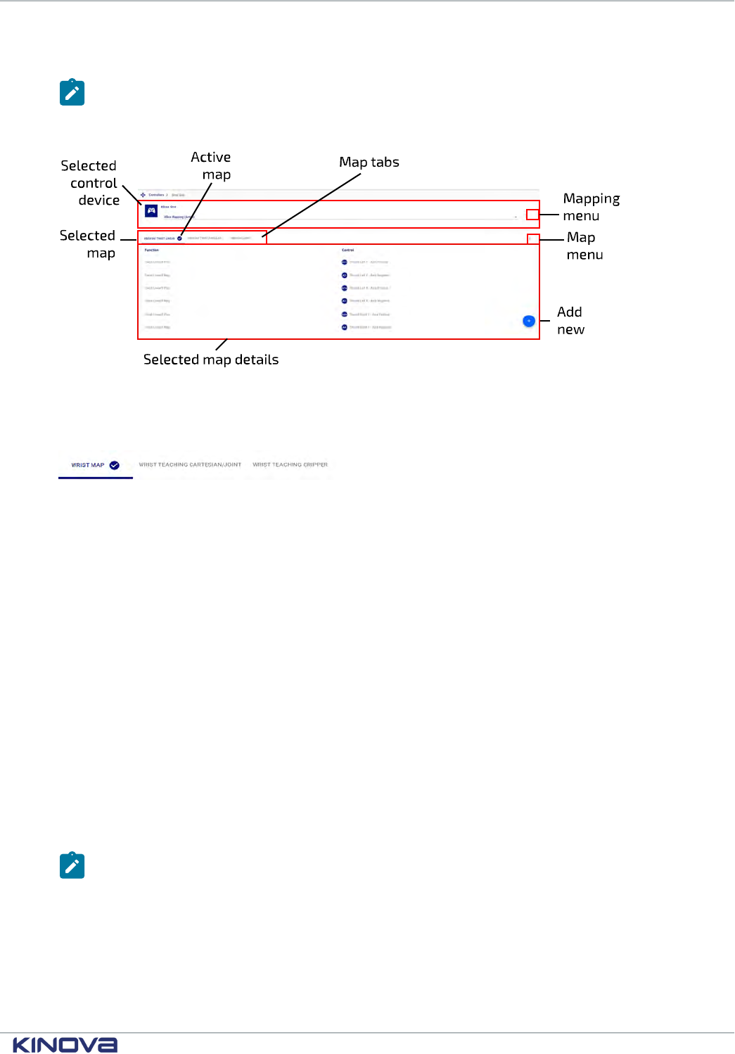
Kinova® Gen3 Ultra lightweight robot User Guide 144
• assigning control inputs as triggers for functions
Note: Pre-defined default mappings are read only. These mappings can however be
duplicated / cloned so that the copy can be edited.
The selected control device is indicated at the top of the window.
Figure 56: Control mapping edit window
At any given time, one map is set as the active map for the controller. At the top of the edit window
is a set of tabs indicating the maps for the control device.
Below the maps tabs is a table showing the map details for the selected map. The selected map is
indicated with a dark blue line under the selected map tab. Clicking on another tab will change the
selected map and the details shown below. Information on the map is shown in a table with two
columns:
• Function - listing defined actions on the robot
• Control - listing control inputs on the control device
Each row of the table represents a single map element for the selected map on the selected control
device.
The active map (the one currently active on the robot, which is not necessarily the one currently
displayed) is indicated with a check mark icon.
A mapping menu is displayed by clicking the three vertical dots icon to the right of the map tabs,
and gives options for the selected map:
• Activate Mapping - makes the selected mapping the active mapping
• Rename - allows you to rename the selected map
• Duplicate - creates a new map that is a duplicate of the selected map
• Delete - deletes the selected map
Note: Since preset mappings are read only, Rename and Delete are not available for preset
mappings.
A map menu is displayed by clicking the three vertical dots icon to the right of the map tabs, and
gives options for the selected map:
• Activate Map - makes the selected map the active map
• Rename - allows you to rename the selected map
• Duplicate - creates a new map that is a duplicate of the selected map
+1 514-277-3777 kinovarobotics.com
© 2022 Kinova inc. All rights reserved.
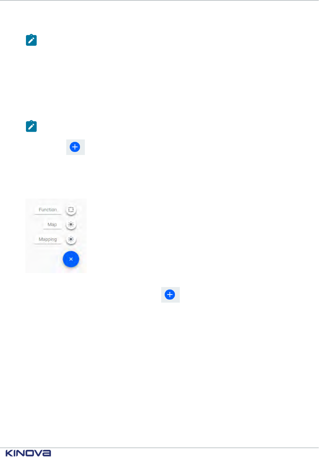
Kinova® Gen3 Ultra lightweight robot User Guide 145
• Delete - deletes the selected map
Note: Since preset mappings are read only, Rename, Duplicate, and Delete are not available
for the maps in preset mappings.
On each row of the table in user-defined maps is a three vertical dot icon. Clicking launches a map
element menu which gives various options for modifying or adding to the chosen map element:
• Change Function - launch the functions menu to modify the action resulting from the control
input
• Assign Control - launch the controls menu to modify the control input
• Rename - rename the map element
• Delete - delete the map element from the map
Note: Since preset mappings are read only, this is not available for the maps of preset
mappings.
The add new ( ) button allows you to add, for the selected control device depending on the
current context:
• a new mapping
• a new map to an existing mapping
• new functions to an existing map
The Functions menu is a pop-out menu giving an interface to add one or more functions to a
selected user-defined map. This launched with + Function.
Figure 57: Functions menu
+1 514-277-3777 kinovarobotics.com
© 2022 Kinova inc. All rights reserved.
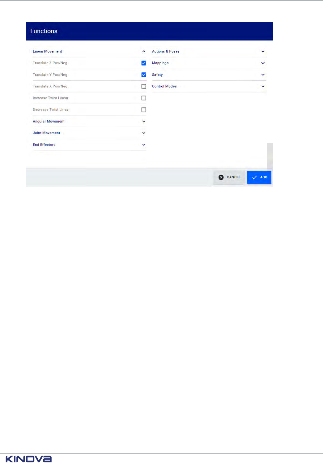
Kinova® Gen3 Ultra lightweight robot User Guide 146
The functions in this menu are divided into groups:
• Linear Movement - translate tool and change speed
• Angular Movement - rotate tool around its own center and change rotation speed
• Joint Movement - navigate from joint to joint and change joint speed
• End Effectors - open or close gripper fingers
• Actions & Poses - initiate or stop an action, or go to a standard defined pose (retract, home,
packaging, zero), take a snapshot
• Mappings - change to the next or previous map in a mapping for the control device
• Safety - apply emergency stop and clear faults
• Control Modes - toggle admittance modes (Cartesian, Joint, Null Space)
The Controls menu is a pop-out menu allowing you to assign, for one of the functions in a map,
the control input which triggers that function. The Controls menu is launched by selecting Assign
Control in the map element menu for one of the functions in a map.
+1 514-277-3777 kinovarobotics.com
© 2022 Kinova inc. All rights reserved.
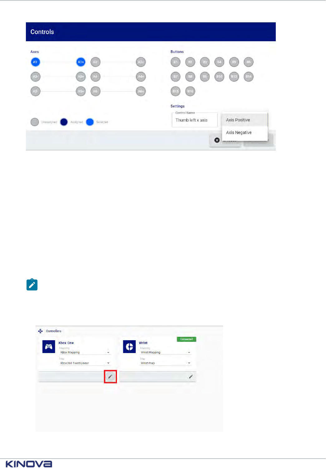
Kinova® Gen3 Ultra lightweight robot User Guide 147
Figure 58: Controls menu
The controls menu shows a graphical representation of all the available controls on the control
devices, whether axis controls (joystick or D-pad) or button controls. The graphical representation
shows which controls have already been assigned, and which are still available.
The specific input for the control used to trigger the function can be specified here.
For an axis control, this means the direction (positive or negative).
For a button control, this means button click, button up, or button down.
Creating a new mapping for a control device
Describes steps to create a new mapping for a recognized control device with the Web App.
About this task
On the Web App Controllers page, users can create and define a new control mapping for a connected control
device.
Note: Mappings can also be created using the Kinova.Api.Base API.
Procedure
1. On the Web App Controllers page, locate the card for the desired control device and choose edit
on the card to launch the control mapping editor for the device.
+1 514-277-3777 kinovarobotics.com
© 2022 Kinova inc. All rights reserved.

Kinova® Gen3 Ultra lightweight robot User Guide 148
2. Click the add new button and select Mapping to create a new empty map.
3. A new empty mapping, labeled 'New Mapping' will appear. This mapping contains no maps, and
the table of functions and controls is blank.
What to do next
Next, you can add and define one or more maps to the mapping by carrying out the 'Creating a new map for a
mapping' procedure once for each new map you want to add to the mapping.
Creating a new map for a mapping
Describes steps to create a new map in a mapping for a recognized control device with the Web App.
Before you begin
A user-defined mapping will already need to have been created for the control device.
About this task
On the Web App Controllers page, you can create and define a new control map for an existing mapping. The
following procedure describes the steps to follow to define a new map.
Note: Control maps can also be defined programmatically using the Kinova.Api.Base
API.
Procedure
1. On the Web App Controllers page, locate the card for the desired control device and click the
edit icon on the card to open the control mapping editor for the device.
2. Select the appropriate mapping from the Mapping dropdown menu.
+1 514-277-3777 kinovarobotics.com
© 2022 Kinova inc. All rights reserved.
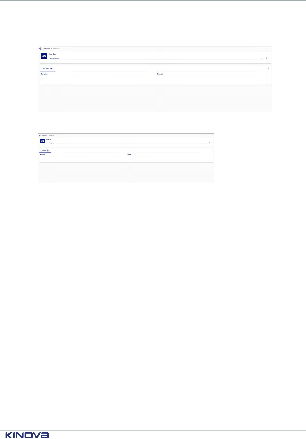
Kinova® Gen3 Ultra lightweight robot User Guide 149
3. Click the add new button and select Map to create a new empty map. A new tab for the map,
labeled 'New Map' will appear. The new map is initally empty, with the functions and controls
empty.
4. If there are other maps in the mapping, click on the tab for the new map to select it. The
selected map details will initially be empty, since they haven't been defined yet.
5. Click the add new button again, this time selecting Function. This will launch the Functions
menu.
6. In the Functions menu, different functions are shown arranged in categories. Select the
functions you want to add to the new map, and then click Add. The added functions will now
appear in the selected map details. The functions will appear in the Function column, while in
+1 514-277-3777 kinovarobotics.com
© 2022 Kinova inc. All rights reserved.
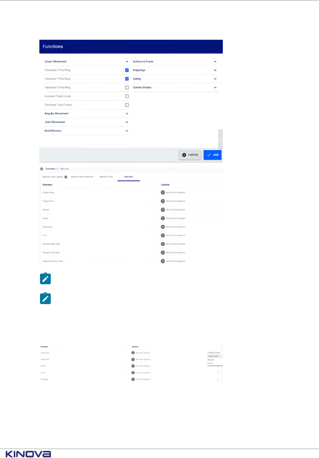
Kinova® Gen3 Ultra lightweight robot User Guide 150
the Control column, 'No Control Assigned' will appear on each row (this is as expected, since
controls have not been assigned yet).
Note: The number of functions you can add to a map will depend on the number of
available types of control inputs for the control device.
Note: It is generally recommended, if possible, to add at least one of the functions in
the Mappings group (Navigate to Next / Previous Map), as well as the Apply Emergency
Stop and Clear Faults functions under the Safety group. This allows you to handle safety
and faults, and to navigate easily from map to map using the control device.
7. For any of the functions, click on the map element menu and select Assign Control from the
menu.
+1 514-277-3777 kinovarobotics.com
© 2022 Kinova inc. All rights reserved.
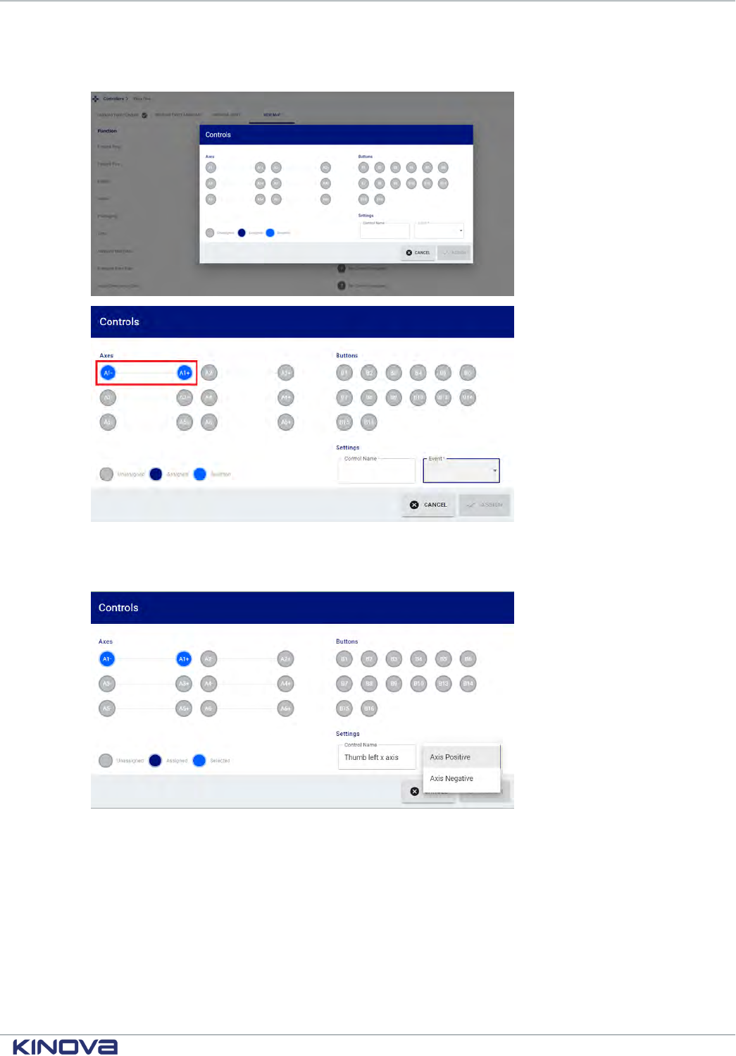
Kinova® Gen3 Ultra lightweight robot User Guide 151
8. This will launch the Controls menu. Using the controller, press one of the unassigned controls.
It will become highlighted on the menu as selected.
9. In the settings, type in a meaningful name for the control input, and select an event for that
control. For axis controls, the options are Axis Positive / Negative and for button controls, the
options are Button Click, Button Up, or Button Down.
+1 514-277-3777 kinovarobotics.com
© 2022 Kinova inc. All rights reserved.
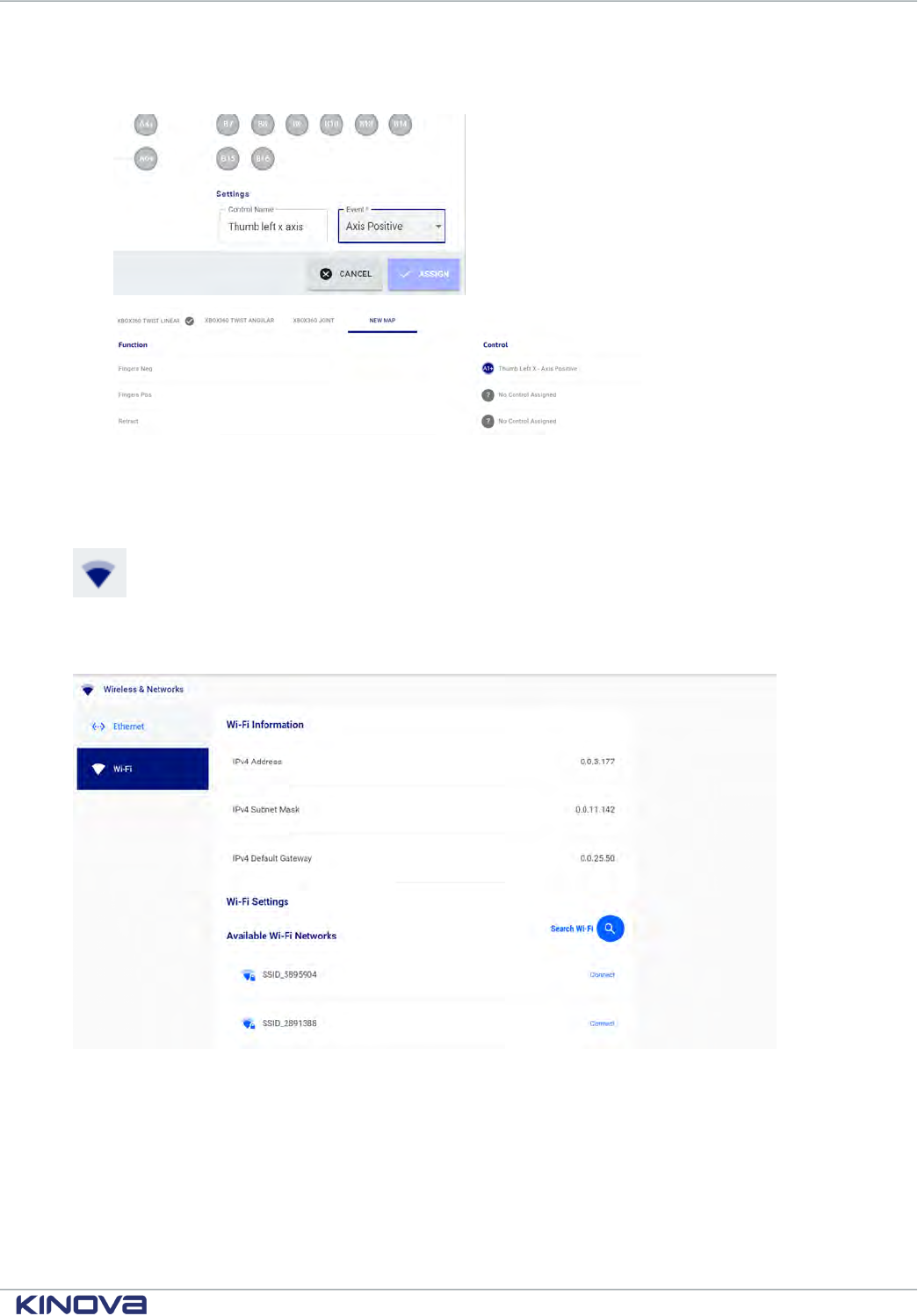
Kinova® Gen3 Ultra lightweight robot User Guide 152
10. When you are happy with the choice, click the Assign button. The selected map details will
update accordingly.
11. Repeat steps 7 through 10 for the remaining functions until all have unique controls assigned.
Wireless & Networks
The Wireless & Networks page of the Web App allows users to configure networks settings.
The Networks page is used to set network parameters for:
• Ethernet
• Wi-Fi
Figure 59: Wireless & Networks page
The page has tabs for each currently available connection method.
The Ethernet Settings tab allows you to configure:
• IPv4 address
• IPv4 subnet mask
• IPv4 default Gateway
+1 514-277-3777 kinovarobotics.com
© 2022 Kinova inc. All rights reserved.
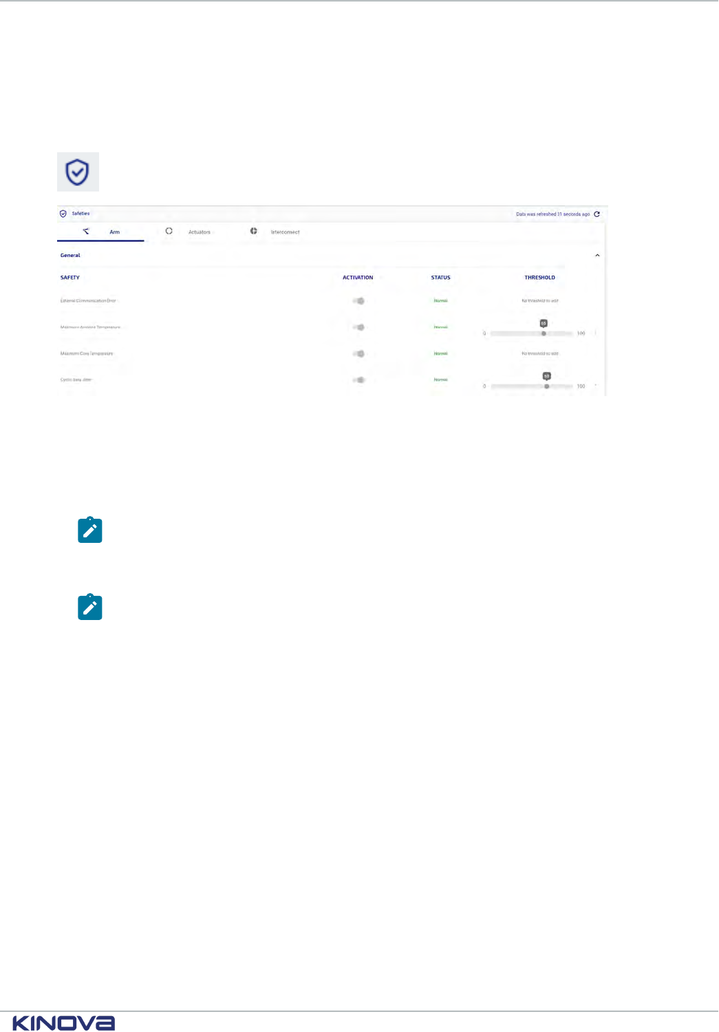
Kinova® Gen3 Ultra lightweight robot User Guide 153
The Wi-Fi Settings tab allows you to enable Wi-Fi networking with the robot and find and connect
to available Wi-Fi networks.
Safeties
The Safeties page of the Web App allows users to view safety settings on the robot.
The Safeties page allows users to view safety thresholds.
Figure 60: Safeties page
There are two types of safety thresholds:
• Error - An error is a departure from normal parameters that is more serious than warnings and
represents a situation which could damage the robot or endanger the user. The thresholds for
errors are set at a more extreme level than warning thresholds.
Note: An error triggers an emergency stop for the robot.
• Warning - A warning serves to signal that the robot is moving away from normal operational
status toward an error state. A warning will not stop the robot.
Note: Some safety items do not have warning thresholds, only error thresholds.
For more detailed information on robot safety thresholds, see here.
Operations page group
The Operations page group of the Web App groups together pages useful to operating the robot.
+1 514-277-3777 kinovarobotics.com
© 2022 Kinova inc. All rights reserved.
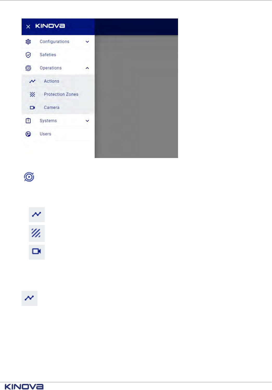
Kinova® Gen3 Ultra lightweight robot User Guide 154
Figure 61: Operations page group
The Operations page group contains pages allowing users to fine tune the configuration and
performance of the robot after the initial setup.
This includes the following pages:
•
Actions
•
Protection Zones
•
Camera
Actions
The Actions page of the Web App allows the user to define and edit robot actions of various types. It also
allows users to play back actions and assemble them together into sequences of action.
The Actions page allows user to define, view, and edit robot actions, as well as build
sequences and play back actions and sequences.
+1 514-277-3777 kinovarobotics.com
© 2022 Kinova inc. All rights reserved.
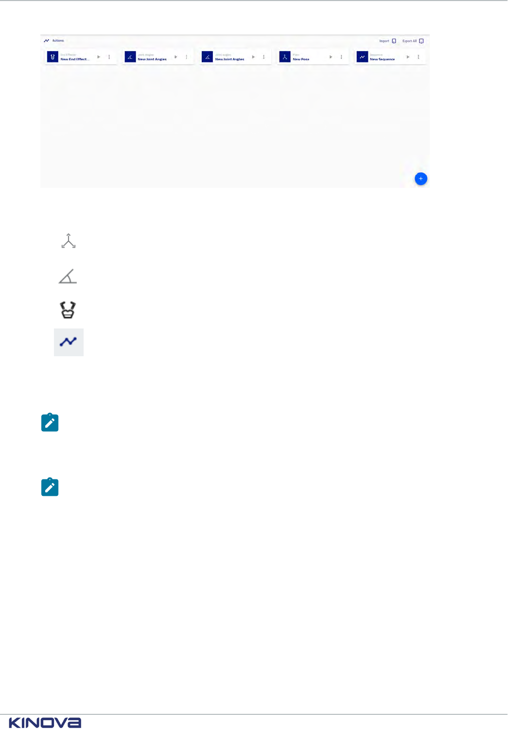
Kinova® Gen3 Ultra lightweight robot User Guide 155
Figure 62: Actions page
Actions available in the Web App are:
•
Pose (go to a Cartesian pose)
•
Joint angles (go to a combination of joint angles)
•
End Effector (change the gripper state)
•
Sequence (take a series of actions one after the other)
A Pose represents a single Cartesian endpoint for the robot. A pose consists of x, y, and z
coordinates representing the position of the end effector, and the three angles θ
x
, θ
y
, and θ
z
representing the orientation of the end effector.
Note: Orientations are represented in x-y-z extrinsic convention.
Angular represents the set of joint angles for each of the arm joints.
End effector represents the gripper state, from 0% (fully open) to 100% (fully closed).
Note: Currently, the Robotiq 2-finger grippers are supported.
A Sequence is an ordered list of actions on. Sequences are a sequential combination of Cartesian
poses, angular settings, and end effector poses. Sequences may also include timed delays between
movements.
The main information panel of the page shows cards with all the defined actions and sequences.
New actions or sequences can be added with the + icon in the lower right of the main panel. This
launches a menu where you can select the type of new item to create.
+1 514-277-3777 kinovarobotics.com
© 2022 Kinova inc. All rights reserved.
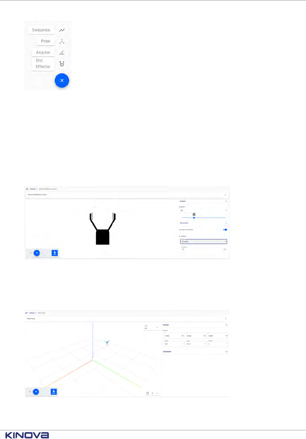
Kinova® Gen3 Ultra lightweight robot User Guide 156
Figure 63: '+' menu
The already defined actions are visible on the Actions page as small cards. From these cards, users
can do the following with an action:
• edit the action
• create a duplicate of the action
• delete the action
• export action as JSON
• export action as XML
Chosing Edit on an action card opens an editor interface specific to the action type. This allows you
to modify the parameters of the action.
Figure 64: End effector action editor
The end effector action editor allows you to modify the endpoint position of the gripper between
0% (fully open) and 100% (fully closed).
There is also an option to apply a duration constraint, in ms. This controls the time taken for the
gripper to complete the movement.
Figure 65: Pose action editor
+1 514-277-3777 kinovarobotics.com
© 2022 Kinova inc. All rights reserved.
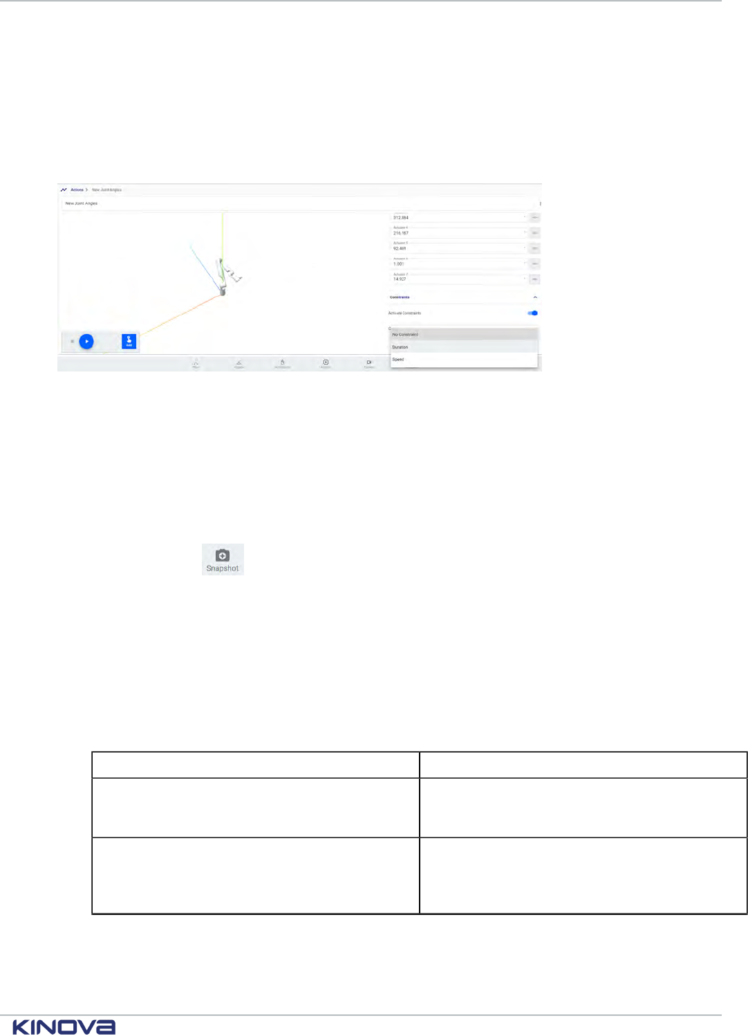
Kinova® Gen3 Ultra lightweight robot User Guide 157
The pose action editor allows you to modify the endpoint position and orientation of the end
effector.
There is also an option to apply a translation speed constraint for the movement toward the
endpoint.
A basic 3D visualization is displayed showing a representation of the base and its frame, and a
sphere with axes representing the tool frame orientation.
Figure 66: Joint angles action editor
The joint angles action editor allows you to modify the angular position, in degrees, for each
actuator on the robot.
A 3D visualization is displayed showing the pose produced by the current angle settings.
There is also an option to apply an angular speed or duration constraint for the movement toward
the endpoint.
Creating actions using snapshot tool
The snapshot button ( ) at the bottom of the screen can be used to capture the current robot
Cartesian pose, angular pose, or gripper state. Any pose captured by the snapshot tool will show up
on the actions page. For more information, see the snapshot tool page.
Preset joint angle actions
The robot comes with several preset joint angle actions viewable and playable in the Web App Actions page.
When the robot is shipped, it comes with several useful preset joint angle actions. These are
viewable and playable on the Actions page.
Table 79: Preset joint angle actions
Name Description
Home Go to the home position, a convenient "ready"
position. This is the same home position
reachable from default Xbox gamepad maps.
Retract Go to the retract position, a folded up,
compact pose for when the robot is not
in use. This is the same retract position
reachable from default Xbox gamepad maps.
+1 514-277-3777 kinovarobotics.com
© 2022 Kinova inc. All rights reserved.
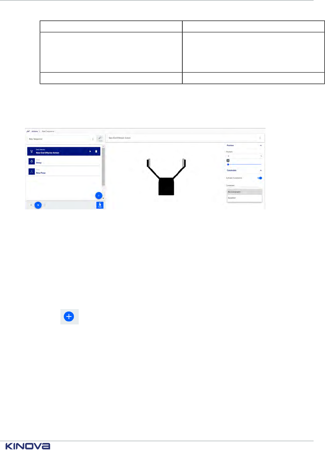
Kinova® Gen3 Ultra lightweight robot User Guide 158
Name Description
Packaging Go to the packaging position (the arrangement
of the robot for packing in the shipping /
storage container). This is useful for
preparing to put the robot back into the
shipping container for transport or storage.
Zero Go to the zero position (all joint angles = 0)
These four preset joint angle actions can all be set to be triggered by control inputs in user-defined
control device maps using either the API or the Web App Controllers page.
Sequence editor
The sequence editor on the Web App Actions page is used to build and edit sequences of actions.
Figure 67: Sequence editor
The sequence editor allows you to:
• create and add a new reach endpoint action (reach Cartesian pose, reach joint angles, reach end
effector position) to a sequence
• add an existing library action to a sequence
• add a delay to a sequence
• reorder actions in a sequence
• edit / configure any actions in the sequence
• enter teaching mode and add snapshots to the sequence
The sequence timeline shows the steps in the sequence.
Clicking the button brings up a menu to pick a new action to add.
+1 514-277-3777 kinovarobotics.com
© 2022 Kinova inc. All rights reserved.
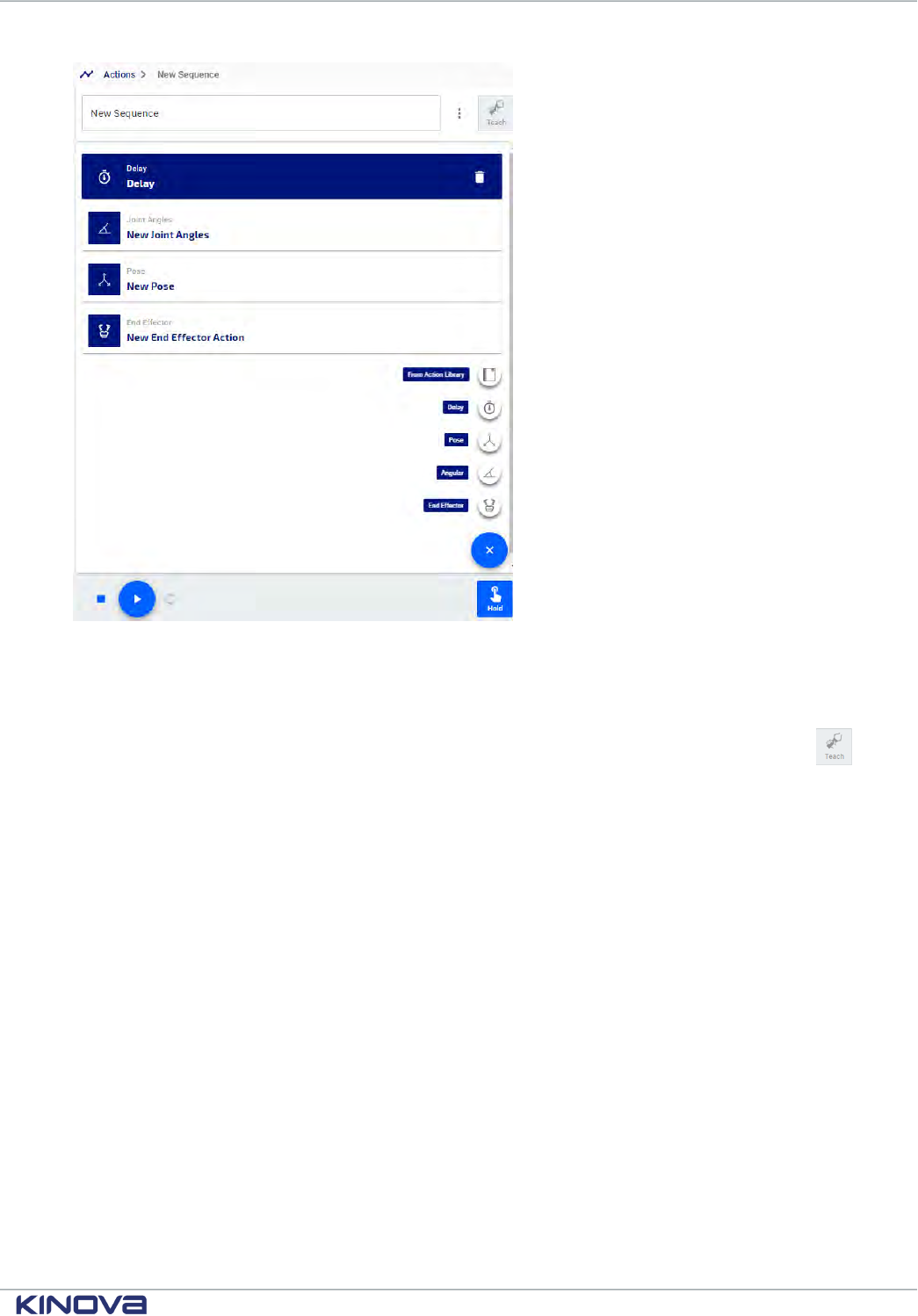
Kinova® Gen3 Ultra lightweight robot User Guide 159
The edit action panel to the right of the sequence list lets you directly edit the parameters of the
action.
Adding actions using teaching mode
Within the sequence editor, you can enter teaching mode by pressing the "Teach" button in the
sequence editor.
+1 514-277-3777 kinovarobotics.com
© 2022 Kinova inc. All rights reserved.
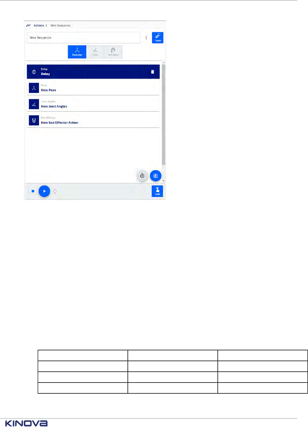
Kinova® Gen3 Ultra lightweight robot User Guide 160
Teaching mode provides a simple interface for placing the robot into one of the available
admittance modes, allowing users to manipulate the robot by hand and take snapshots.
Snapshots can be captured in one of two ways:
• using the on screen snapshot button that appears when teaching mode is initiated
• using the physical buttons on the interface wrist buttons
The type of snapshot taken depends on the admittance mode chosen. In Cartesian admittance, a
Cartesian pose snapshot is captured. In joint or null space admittance, a joint angles snapshot is
captured.
If a snapshot is captured, and the gripper position is changed since the previous point in the
sequence, both robot position and gripper position snapshots will be captured.
If the gripper position was unchanged, only the robot position will be captured.
If a snapshot is taken for the first point in a sequence, both robot position and gripper position
snapshots will be captured.
Teaching / gripper wrist button map
Entering teaching mode changes the control mapping of the interface module buttons as follows:
Input Button 1 Button 2
button click open gripper take snapshot
button hold close gripper N/A
button release stop gripper N/A
Deleting actions or re-ordering the steps of a sequence
+1 514-277-3777 kinovarobotics.com
© 2022 Kinova inc. All rights reserved.
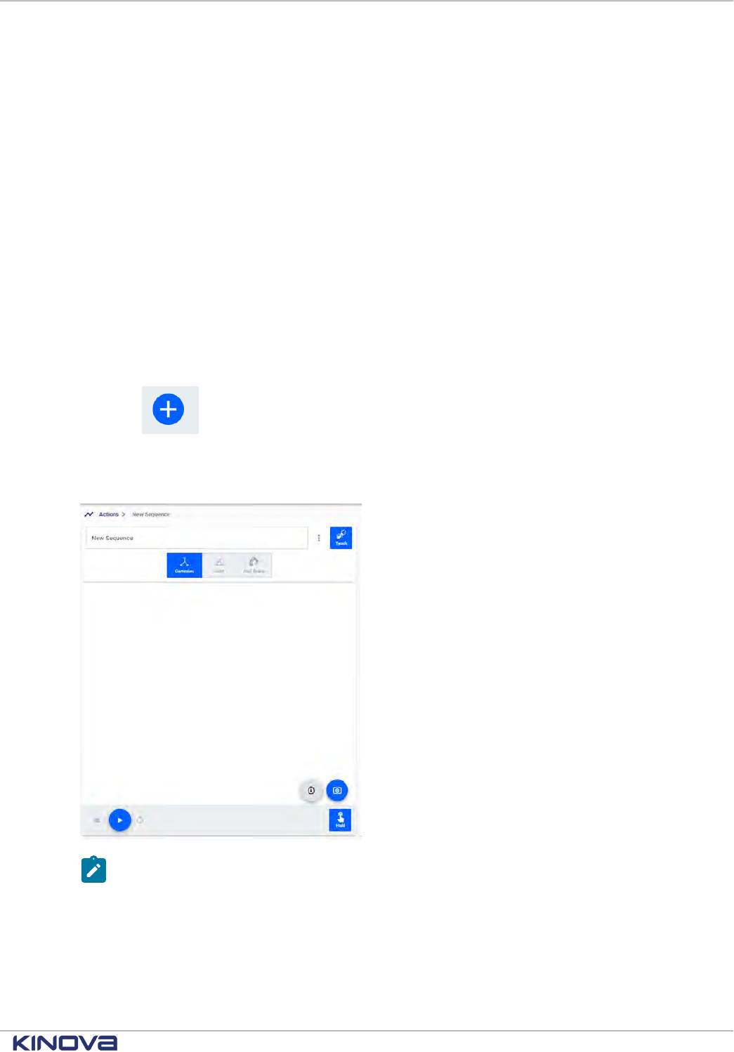
Kinova® Gen3 Ultra lightweight robot User Guide 161
If you want to change the position of an action in the sequence, or remove it from the sequence
entirely, simply click and drag to move the selected action and release it in the desired position.
To delete a selected action from the sequence, click the delete icon on the action.
Creating a new sequence in teaching mode
Describes steps to define a new sequence on the robot using teaching mode within the sequence editor.
Before you begin
The robot needs to be powered on, and in the home position or other stable position.
About this task
Teaching mode is a mode that is launched from the Web App sequence editor. Enabling this mode puts the
robot into a selected admittance mode and changes the mapping of the wrist buttons on the robot interface
module. This allows you to freely manipulate the robot by hand and take snapshots of positions (Cartesian
pose or joint angles, depending on the selected admittance mode) as well as gripper positions. By running
through a few positions, a new sequence can easily and quickly be created.
Procedure
1. Connect to the robot via the Web App and navigate to the Actions page.
2.
Click the '+' button to create a new action, and select Sequence from the pop up menu.
The sequence editor will open with an empty sequence.
3. Click the Teach button and select from the available admittance modes options (Cartesian and
Joint for 6 DoF robot, Cartesian, Joint, and Nullspace for 7 DoF robot).
Note: The robot will be set into teaching mode, with the robot in the chosen admittance
mode. The buttons on the interface module wrist will also be changed from the default
map to the teaching mode map.
4. Manipulate the robot by hand, and use the wrist buttons to take a snapshot of the robot
position, or open/close the gripper fingers.
5. Repeat step 5 as needed to capture the different components of the desired movement by the
robot and gripper.
+1 514-277-3777 kinovarobotics.com
© 2022 Kinova inc. All rights reserved.
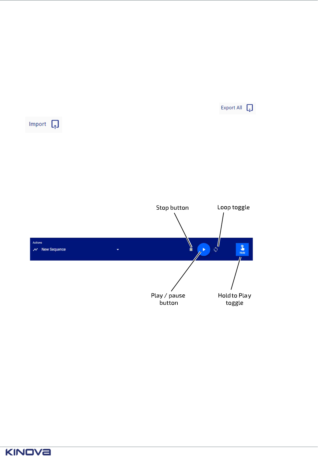
Kinova® Gen3 Ultra lightweight robot User Guide 162
6. Click the Teach button again to exit teaching mode.
7. Home the robot to return to a stable starting position, and then click play to play back the
sequence.
8. If desired, you can finetune the sequence by using the sequence editor to insert and configure
any needed delays in the sequence, or to add duration or speed constraints to sequence steps.
Importing and exporting actions or sequences
This section describes functionalities available on the Actions page for importing and exporitng actions or
sequences.
You can Export All defined actions or sequences as XML or JSON, to share with others. Similarly,
a JSON or XML action file can be imported from the computer. The Export All and
Import functions are available at the top of the main panel.
Playing back actions and sequences
Actions and sequences can be played back from the Actions page, and controls are provided to manage
playback.
When an action or sequence is selected by clicking on its card, the item is loaded in a playback bar at
the bottom of the page.
Figure 68: Actions playback bar
When the play button is pressed, the robot will move directly to execute the described action or
sequence.
The Hold to Play toggle (by default, activated) controls the playback. When the toggled on, the
playback will only continue as long as the play button is held down. When not toggled on, a single
press of the play button will suffice for the playback to execute completely.
The Play button plays the sequence.
The Pause button (the Play button changes to a Pause button while the sequence is playing) will
stop the playback while keeping the playhead at the same position. When the play button is pressed
again, the motion will continue exactly where it left off.
The Stop button will stop the movement and return the playhead to the beginning.
+1 514-277-3777 kinovarobotics.com
© 2022 Kinova inc. All rights reserved.
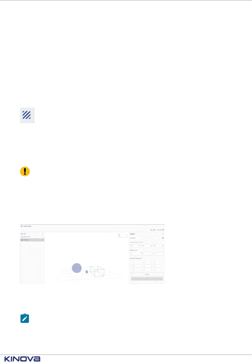
Kinova® Gen3 Ultra lightweight robot User Guide 163
In the case of a Cartesian pose, angular position, or gripper position, the robot (or gripper) will
interpolate linearly between the present position and the target position and move smoothly and
directly to the target position.
For a sequence, the robot will first go directly to the the first item in the sequence, and then
will trace out a path that goes through the positions on the sequence. A progress bar above the
playback bar shows the progress of the playback through the steps.
For sequences, an additional Loop toggle control can be toggled on or off. When toggled on, a
sequence will play through all the steps and then go directly to the pose of the first step. This is
useful for demonstrations.
Protection Zones
The Protection Zones page of the Web App allows users to define zones around the robot where movement is
prevented or limited.
The Protection Zones page allows user to define and activate multiple three-dimensional
geometric volumes around the robot where the robot:
• cannot go, and, optionally,
• the maximum speed is constrained
A protection zone is intended to limit the possibility of the robot running into either the user or
objects near the robot.
Important: Protection zones only work when controlling the robot in Cartesian mode; when
controlling the robot in Angular mode, they are ignored.
Zone Shapes
Three protection zone shapes are available:
• Rectangular prism
• Sphere
• Cylinder
Figure 69: Protection Zones page
The Protection Zones page allows for defining, configuring, and viewing protection zones.
Multiple protection zones can be active at the same time.
Note: The robot control library applies protection zones in the course of executing any
high-level motion commands. There are no hard limits to the number of simultaneous
active protection zones, but for best performance, we recommend activating at most four
protection zones at the same time.
+1 514-277-3777 kinovarobotics.com
© 2022 Kinova inc. All rights reserved.
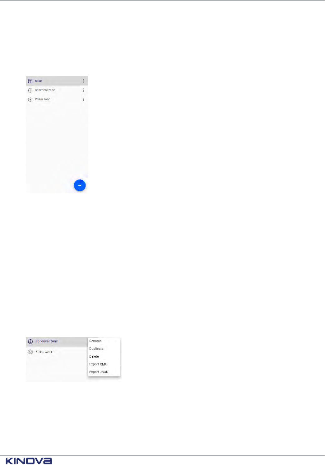
Kinova® Gen3 Ultra lightweight robot User Guide 164
The Protection Zones page is divided into three main sections:
• Zones panel
• Views panel
• Zones configuration panel
Zones panel
The zones panel is used to create new protection zones. It also lists the already defined zones and
allows users to rename, duplicate, and delete existing protection zones. It also allows users to
export individual protection zones as XML or JSON.
The panel lists the already defined protection zones. Clicking on a list entry selects that entry,
highlighting the zone in the list and:
• highlighting the zone in the views panel
• brings up a configuration form for that zone in the zones configuration panel
A 'more' icon made up of three vertical dots on the right side of each list entry brings up a menu
with the following options:
• Rename - enter a recognizable / meaningful name for the selected protection zone
• Duplicate - create a new zone that is a duplicate copy of the selected existing zone
• Delete - delete the selected zone
• Export XML - export the present saved configuration of the zone as XML
• Export JSON - export the present saved configuration of the zone as JSON
A new protection can be added by clicking the + sign icon at the bottom of the zone panel and
selecting from the list of protection zone types.
+1 514-277-3777 kinovarobotics.com
© 2022 Kinova inc. All rights reserved.
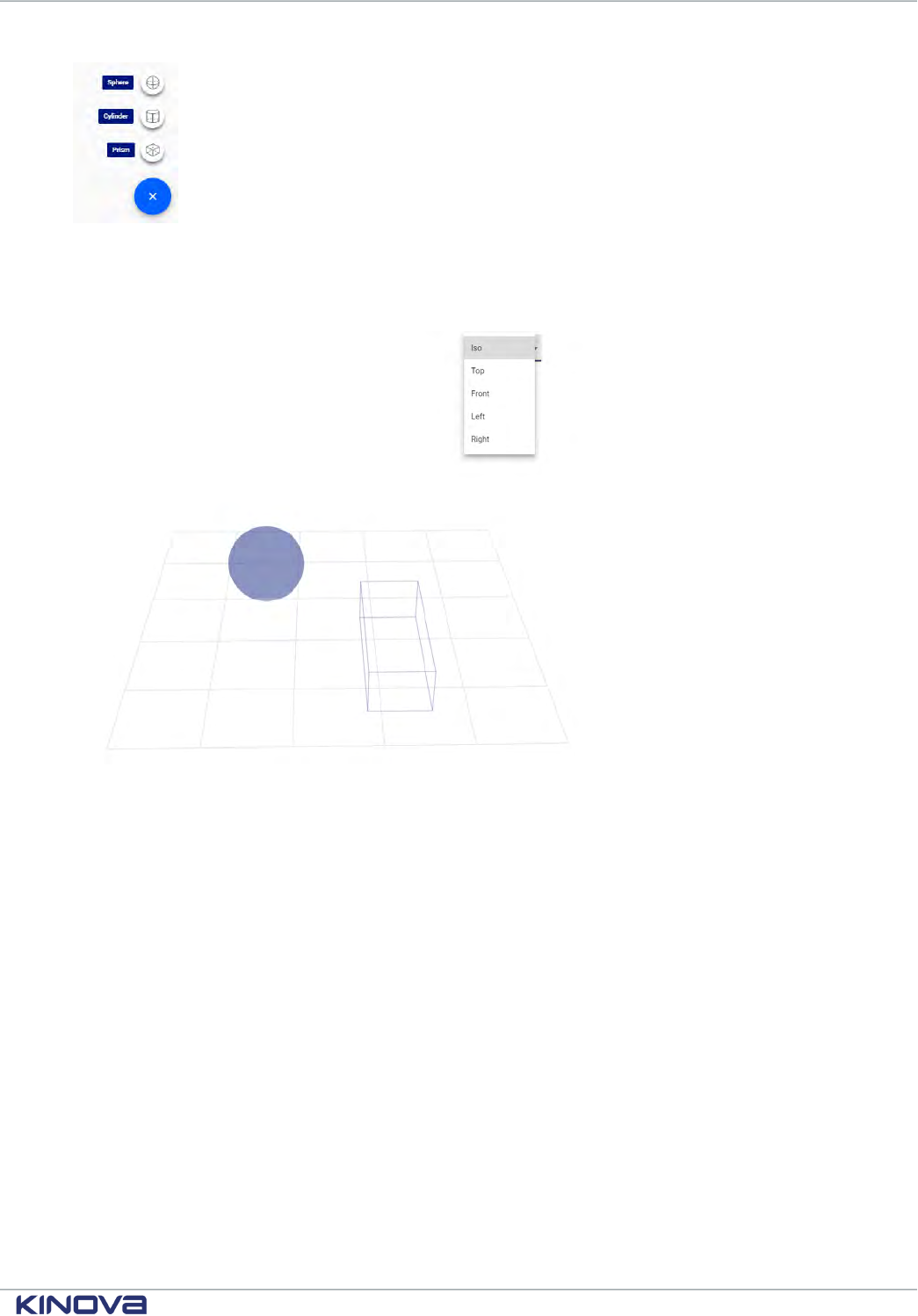
Kinova® Gen3 Ultra lightweight robot User Guide 165
This will create a new, empty protection zone for the selected type, and add an entry to the zone
panel list.
Views panel
The views panel offers a live visualization of the defined protection zones. The visualization can
display the zones in several different views:
• Iso (isometric) view
• Top view
• Front view
• Left view
• Right view
For the isometric view, you can drag on the screen to change the view angle. The other options
allow a view from a fixed perspective.
Zones configuration panel
+1 514-277-3777 kinovarobotics.com
© 2022 Kinova inc. All rights reserved.
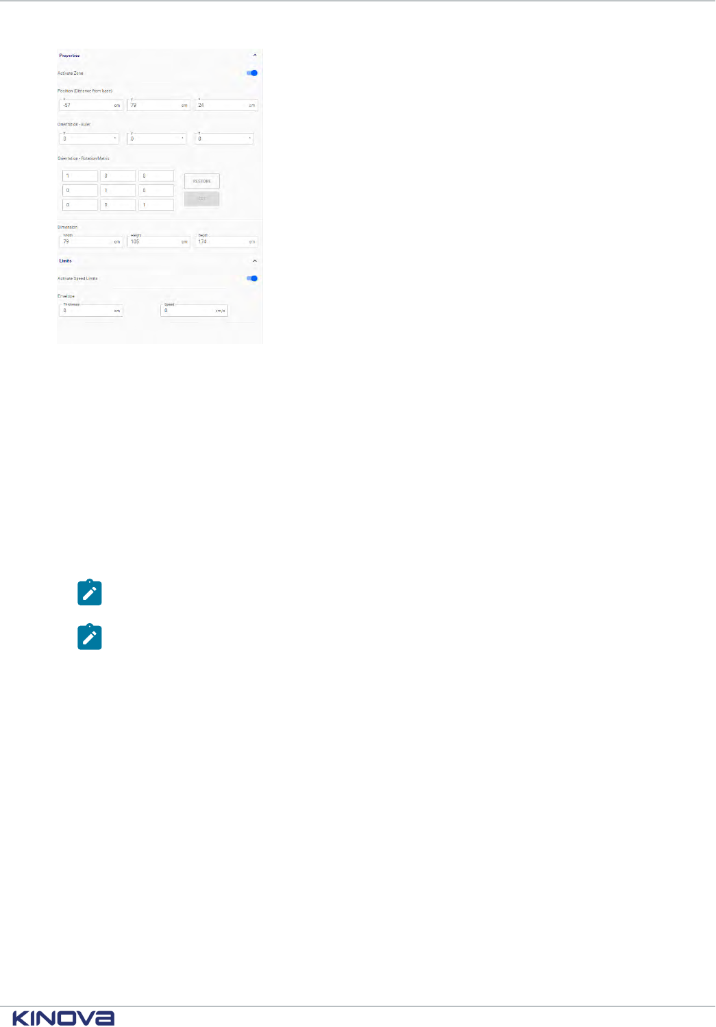
Kinova® Gen3 Ultra lightweight robot User Guide 166
The zones configuration panel allows you to configure the presently selected protection zone. The
panel is divided in two sections:
• Properties
• Limits
The properties section is for defining the area where the defined checkpoints on the robot cannot
go. This allows you to:
• Activate/deactivate a zone
• Set the position of the center of the zone in terms of the base frame
• Set the orientation of the protection zone, either as a set of three Euler angles or as a rotation
matrix
Note: Orientation is defined as rotations around a frame aligned with the base frame and
centered on the center of the protection zone
Note: Orientation can be set for prism and cylinder shapes only (spherical region
symmetric to rotations around its own center)
• Dimensions of the zone
The configurable dimensions of the zones are:
• Prism shape - height, width, and depth
• Cylinder shape - height and radius
• Sphere shape - radius
The limits section defines an envelope around the 'no-go' zone where the speed of the robot is
constrained. An envelope is a three dimensional region bounded by the outer boundary of the no-go
zone and a larger zone that is the same shape, but extending out a certain thickness beyond the no-
go zone. The limits section allows you to:
• Activate/deactivate limits
• Define an envelope thickness (in cm, between 0 and 200 cm)
• Define an envelop speed limit (in cm/s, between 0 and 10 cm/s)
Camera
The Camera page of the Web App allows users to view the live feed from the vision module color sensor.
+1 514-277-3777 kinovarobotics.com
© 2022 Kinova inc. All rights reserved.
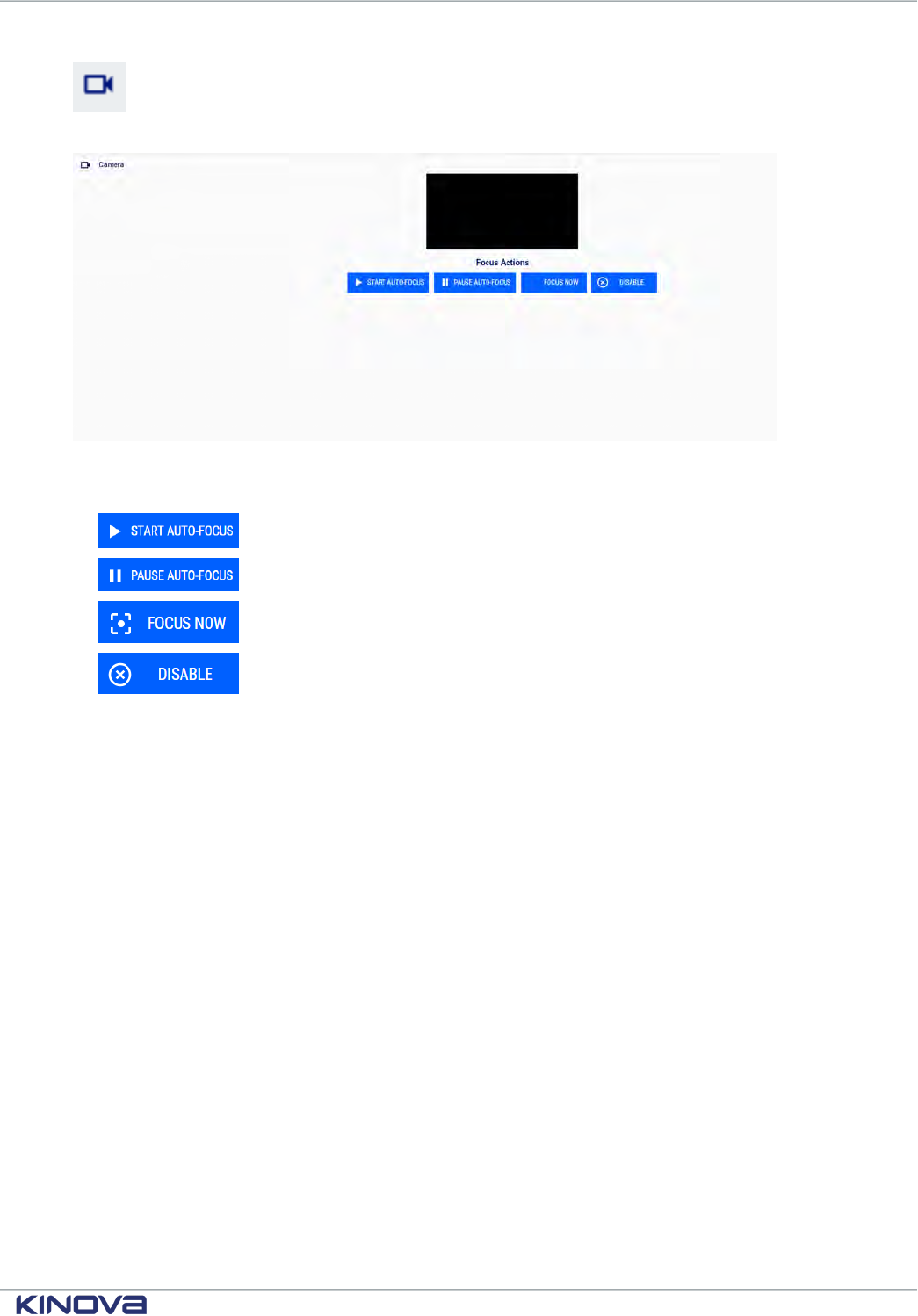
Kinova® Gen3 Ultra lightweight robot User Guide 167
The Camera page allows you to see the live feed from the color sensor of the installed vision
module.
Figure 70: Camera page
There are four controls available on this page:
•
Start auto-focus
•
Pause auto-focus
•
Focus now
•
Disable auto-focus
Systems page group
The Systems page group of the Web App groups together pages to update and view status and configiration
information for the system.
+1 514-277-3777 kinovarobotics.com
© 2022 Kinova inc. All rights reserved.
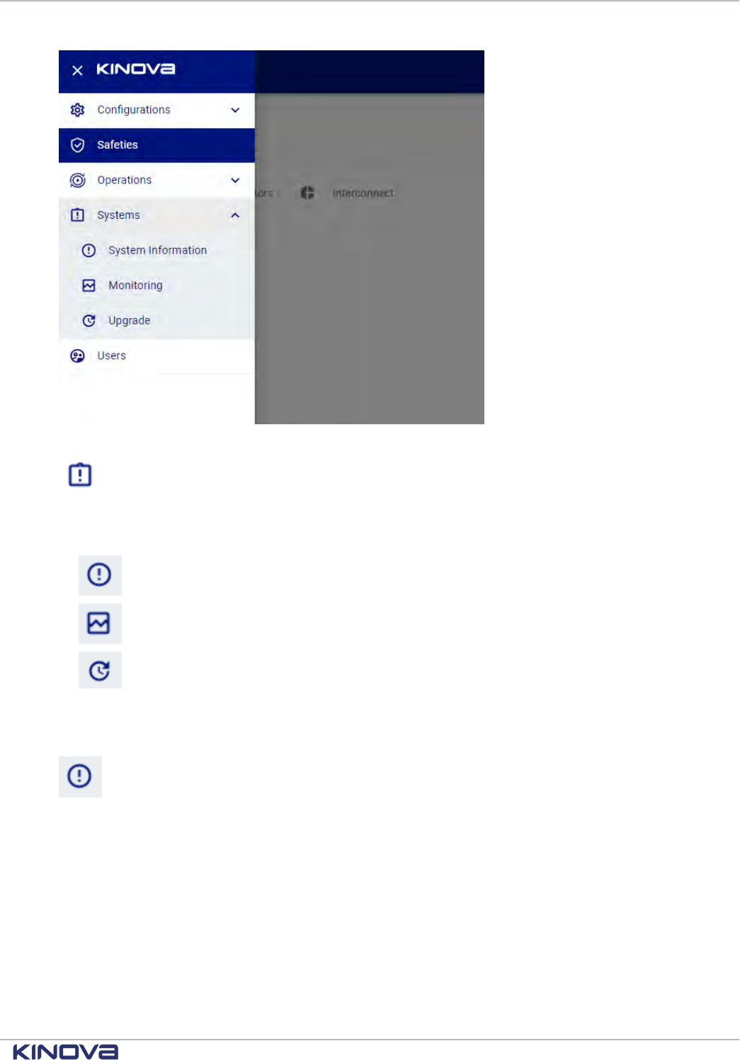
Kinova® Gen3 Ultra lightweight robot User Guide 168
Figure 71: Systems page group
The Systems page group contains pages for robot devices information, monitoring, and
software/firmware upgrades.
It contains the following pages:
•
System Information
•
Monitoring
•
Upgrade
System Information
The System Information page of the Web App provides high-level hardware and firmware details for the robot.
The System Information page gives a quick high level view of hardware and firmware
configuration details.
+1 514-277-3777 kinovarobotics.com
© 2022 Kinova inc. All rights reserved.
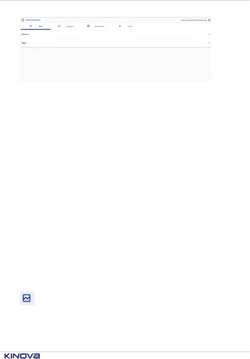
Kinova® Gen3 Ultra lightweight robot User Guide 169
Figure 72: System Information page
The information on the page is displayed within different tabs:
• Arm (product and base)
• Actuators (for each of the individual actuators in robot)
• Interconnect (interface module)
• Vision
For the base, actuators, interface module, vision module, information is given on:
• bootloader version
• device type
• firmware version
• MAC address
• part number, part number revision, and serial number
Product gives product-level information:
• KIN (Kinova information number)
• model ID
• model year
• assembly plant
• degrees of freedom
• base type
• end effector type
• vision module type
• interface module type
• arm laterality
• wrist type
Monitoring
The Monitoring page of the Web App allows users to view real-time monitoring information on the status and
performance of the robot.
The Monitoring page allows for real-time monitoring of status and performance information
for the robot. The monitoring page is the first page that opens when opening a new session using
the Web App.
+1 514-277-3777 kinovarobotics.com
© 2022 Kinova inc. All rights reserved.
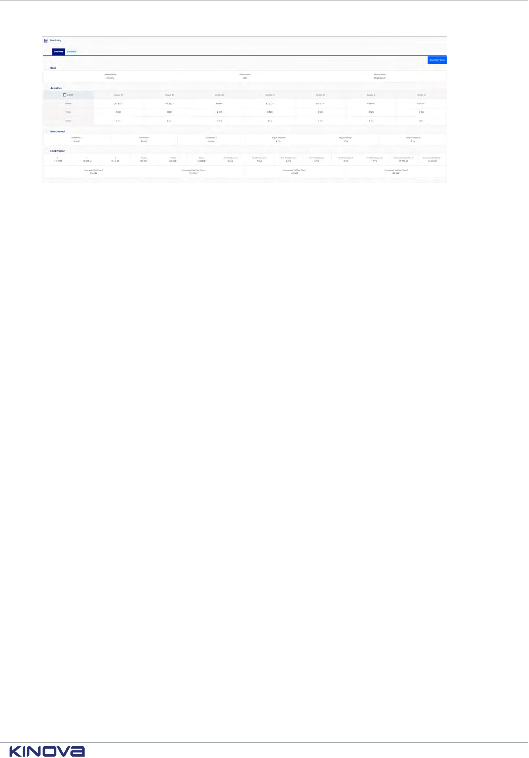
Kinova® Gen3 Ultra lightweight robot User Guide 170
Figure 73: Monitoring page
The monitoring information is divided into sections:
• Base
• Actuators
• Interconnect (interface module)
• End effector
There are two tabbed views available, selectable through three tabs at the top of the screen:
• Overview
• Detailed
Overview tab contents
The Overview tab shows the following information in each section:
• Base
º operating mode (maintenance, update, shutting down, run, in fault)
º control mode (angular joystick, Cartesian joystick, torque control, Cartesian admittance, joint
admittance, null space admittance)
º servoing mode (single level (high level), low level)
• Actuators - for each joint:
º measured position (°)
º measured torque (N·m)
º measured velocity (°/s)
• Interconnect (interface module)
º
acceleration - x, y, and z (m/s
2
)
º angular velocity x, y, and z of interconnect (°/s)
• End effector
º position and orientation - x, y, z, θ
x
, θ
y
, θ
z
º velocity - x, y, z, θ
x
, θ
y
, θ
z
º tool Twist - x, y, z, θ
x
, θ
y
, θ
z
º External tool wrench force - x, y, z
º External tool wrench torque - x, y, z
º Commanded tool pose - x, y, z, θ
x
, θ
y
, θ
z
Detailed tab contents
+1 514-277-3777 kinovarobotics.com
© 2022 Kinova inc. All rights reserved.

Kinova® Gen3 Ultra lightweight robot User Guide 171
The detailed tab shows the following information in each section:
• Base
º operating mode (maintenance, update, shutting down, run, in fault)
º control mode (angular joystick, Cartesian joystick, torque control, Cartesian admittance, joint
admittance, null space admittance)
º servoing mode (single level (high level), low level, bypass)
º arm voltage (V)
º arm current (A)
º CPU temperature (°C)
º ambient temperature (°C)
º
acceleration x, y, z of the base (m/s
2
)
º angular velocity x, y, z of base (°/s)
• Actuators - for each joint:
º measured position (°)
º measured velocity (°/s)
º measured torque (N·m)
º motor current (A)
º voltage (V)
º motor temperature (°C)
º core temperature (°C)
• Interconnect
º
acceleration x, y, z of interface (m/s
2
)
º angular velocity x, y, z of interface (°/s)
º voltage (V)
º core temperature (°C)
• End effector
º position and orientation - x, y, z, θ
x
, θ
y
, θ
z
º tool Twist - x, y, z, ω
x
, ω
y
,
z
º External tool wrench force - x, y, z
º External tool wrench torque - x, y, z
º Commanded tool pose - x, y, z, θ
x
, θ
y
, θ
z
Exporting a snapshot of monitoring data
It is possible to export a snapshot of the currenting monitoring data for the robot.
By pressing the snapshot data button ( ), you have the ability to save a dump of the
monitoring data locally on your computer to JSON format. This can be useful information to share
with Kinova support for troubleshooting purposes.
Upgrade
The Upgrade page of the Web App is used to update the software of the robot with a downloaded software
package.
The Upgrade page provides a simple interface to perform upgrades to the robot.
+1 514-277-3777 kinovarobotics.com
© 2022 Kinova inc. All rights reserved.
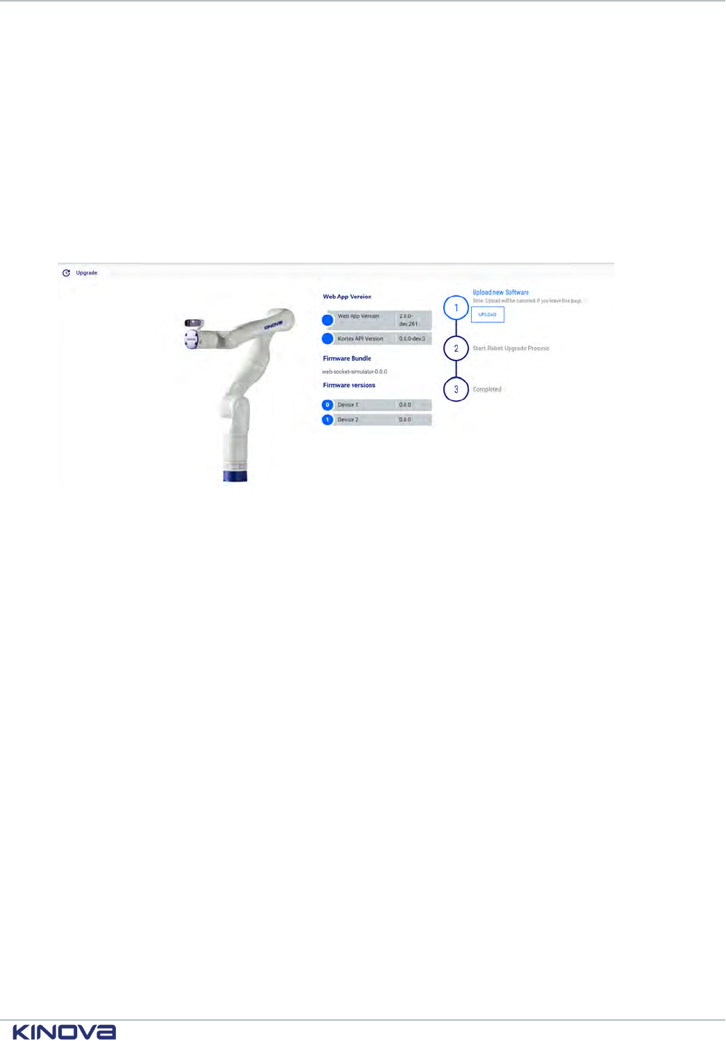
Kinova® Gen3 Ultra lightweight robot User Guide 172
Robot upgrade files are bundled as a package (.swu file).
The robot upgrade package includes:
• robot devices firmware updates:
º base controller
º actuators
º interface module
º vision module
• Web App upgrade package
•
Kinova
®
Kortex™ API upgrade package
Figure 74: Upgrade page
The upgrade page provides an interface to upload a new upgrade package and initiate the upgrade.
The page also provides information on the current Web App and Kinova
®
Kortex™ API versions, as
well as the current firmware versions of the robot devices.
Upgrading the robot firmware and software
This section describes how to upgrade the robot firmware and software using the Web App.
Before you begin
• A new robot update package needs to have been previously downloaded to the development
computer.
• The development computer needs to be connected to the robot, either via wired Ethernet
connection or via Wi-Fi.
• The user needs to have a Web App session open on the robot.
About this task
The Web App is used to upgrade the robot firmware and software using a new upgrade package on the
development computer. The upgrade package covers all devices in the arm, and all devices are upgraded as
part of this process.
Procedure
1. Browse to the Web App Upgrade page.
2. Click the Upload button on "Upload New Software."
3. Browse the development PC disk to select the new firmware package. The new package will
upload to the robot. If the upload is unsuccessful, you will receive an error message. If it is
successful, the process will continue.
+1 514-277-3777 kinovarobotics.com
© 2022 Kinova inc. All rights reserved.
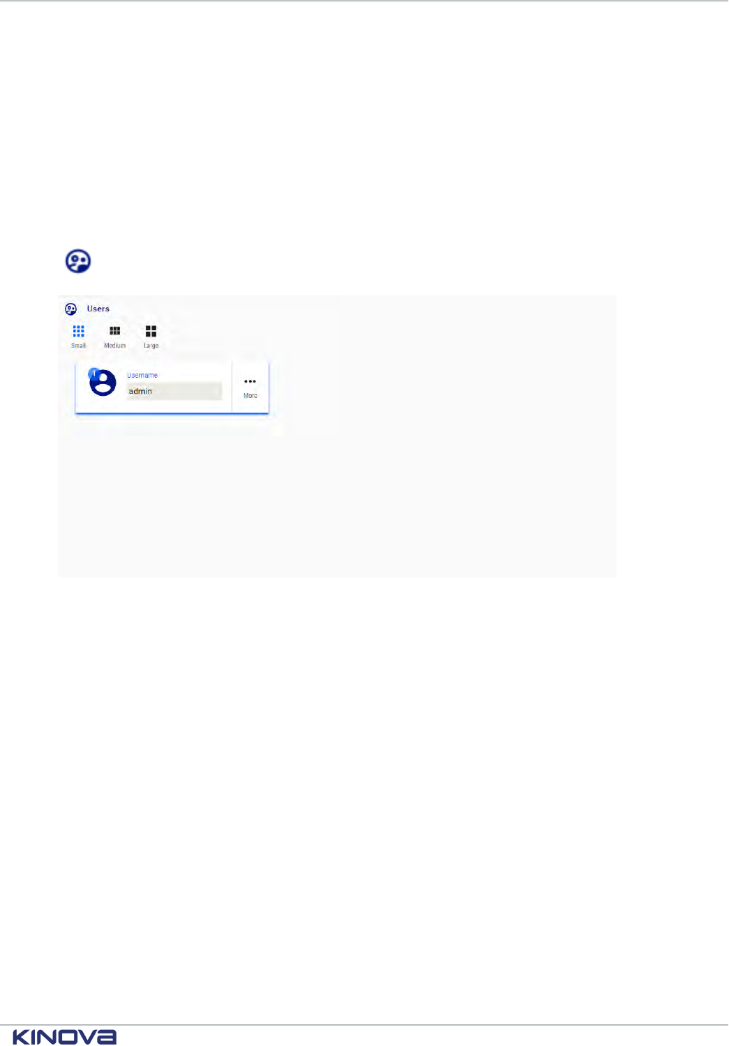
Kinova® Gen3 Ultra lightweight robot User Guide 173
4. Once the firmware package uploads successfully, you will be able to start the upgrade. The Web
App will refresh twice during the upgrade, and each time you will have to login again. If you login
during the upgrade, the Upgrade page will indicate that the upgrade is in progress.
Results
The LED on the base of the robot is green when the process is over. The Web App also indicates when the
process is finished.
Users
This section describes the Users page of the Web App allows for editing user profile information.
The Users page is used to define, set, and edit user profiles for the robot.
Figure 75: Users page
Defined profiles are displayed as information cards on the main information panel of the page. The
cards are in three different sizes:
• large
• medium
• small
Card sizes can be toggled using buttons on the upper right of the main information panel.
Large cards show a full set of information. The large card displays the user name and language.
Medium cards are slightly smaller.
Small cards show a more compact view. By clicking the More button, a pop-up menu is revealed to
allow you to View, Edit, Delete, or Duplicate the profile.
Clicking Edit brings you to an editing interface where it is possible to configure the profile.
+1 514-277-3777 kinovarobotics.com
© 2022 Kinova inc. All rights reserved.
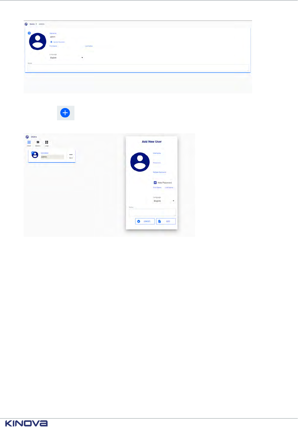
Kinova® Gen3 Ultra lightweight robot User Guide 174
Figure 76: Card editing interface
Click on the button in the lower right corner of the page to create a new user. This launches a
menu to add information for the new user.
Figure 77: Create new user
Creating a new user profile
This section describes how to create a new user profile in the Web App.
+1 514-277-3777 kinovarobotics.com
© 2022 Kinova inc. All rights reserved.
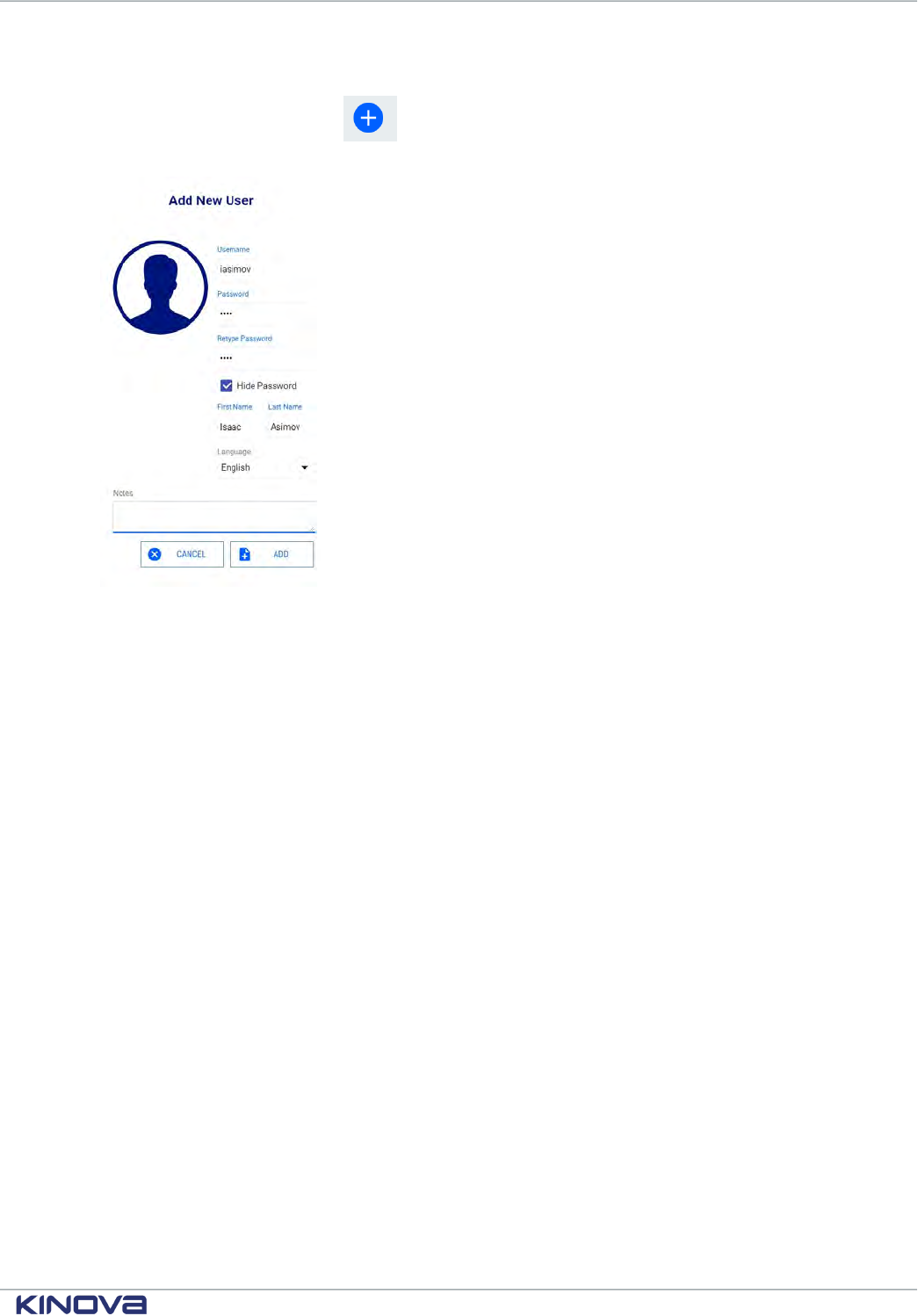
Kinova® Gen3 Ultra lightweight robot User Guide 175
Procedure
1.
On the Users page, press the button to add a new empty user profile. This will bring up a
window to enter information for the profile.
2. Enter the information for the user profile including name, user name, and password.
3. When you are done adding information, press ADD to create the new user profile.
Results
The new user profile will be created. The next time you log on to the Web App, you will be able to log in with
these credentials.
+1 514-277-3777 kinovarobotics.com
© 2022 Kinova inc. All rights reserved.

Kinova® Gen3 Ultra lightweight robot User Guide 176
Kinova® Kortex™ Developer Guide
Introduction
This section of the documentation provides guidance on developing custom software applications for the
robot.
Your robot is enabled by Kinova
®
Kortex™, the Kinova software framework and application
development platform. This growing and evolving framework will allow you to configure and
control the robot programmatically, adapting to your specific needs and supporting you in
integrating new Kinova products into robotics applications. The Kinova
®
Kortex™ API supports
multiple robot products from Kinova as a cross-hardware development framework.
Note: Some of the specific features of the API are hardware dependent and may not be
available on your robot.
APIs are currently provided for the following languages:
• C++
• Python
•
MATLAB
®
(simplified API supporting a subset of Kortex functionality)
Kinova also offers ROS packages covering most of the same functionalities.
The pages that follow describe the general philosophy and approach of the APIs.
The following GitHub respositories contain additional developer guidance and resources, including
detailed API documentation, setup instructions, and source code examples:
•
Kinova
®
Kortex™ API: kinovarobotics/kortex
•
Kinova
®
Kortex™ ROS: kinovarobotics/ros_kortex
•
Kinova
®
Kortex™ ROS Vision: kinovarobotics/ros_kortex_vision
•
Kinova
®
Kortex™ MATLAB
®
API: kinovarobotics/matlab_kortex
Tutorial videos are available on the Kinova
®
YouTube channel (https://www.youtube.com/watch?
v=zQewb08M4sA).
Devices and services
This section describes the concept of devices and services in the robot.
The API consists of services which define interfaces implemented and available on the various
robot devices.
The robot consists of several devices:
• base controller
• actuators (each actuator is a distinct device)
• interface module
• vision module
A service consists of methods and communication exchange data structures. The devices in the
robot each implement a particular set of services, some of which are available across multiple
devices. The methods available as part of a service on a device are accessed via remote procedure
calls (RPC).
+1 514-277-3777 kinovarobotics.com
© 2022 Kinova inc. All rights reserved.
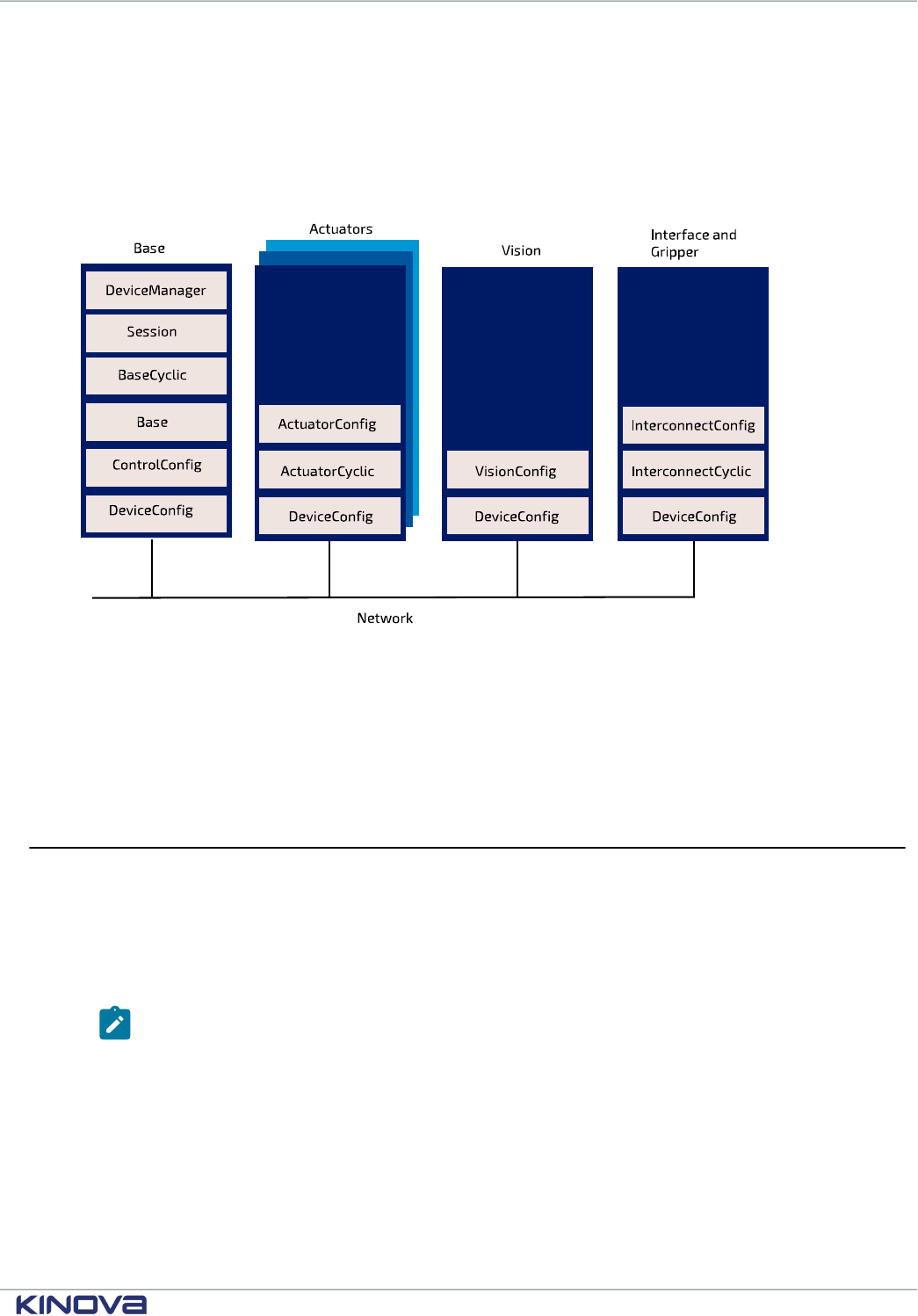
Kinova® Gen3 Ultra lightweight robot User Guide 177
Figure 78: Services on multiple devices
Available services
This section lists the available robot services for the robot.
Kinova makes available a number of services for developers, each of which includes functions and
data types supported for C++ and Python.
• Session - provides functions for opening and closing sessions with the robot. This service is
used at the beginning and end of every session with the robot to authenticate the user.
Note: In practice, end users will not use the Session service directly, but will use a
SessionManager object. See the GitHub documentation for more details.
• Base - broadly useful service. Provides functions for configuring a range of base-related
functionalities as well as high-level control for the robot.
• DeviceManager - provides a list of device information used for internal communication routing
purposes.
• Cyclic data communications (sending commands to devices and/or receiving status feedback on
a periodic or as-requested basis). Cyclic data communications are used with low-level or low-
+1 514-277-3777 kinovarobotics.com
© 2022 Kinova inc. All rights reserved.

Kinova® Gen3 Ultra lightweight robot User Guide 178
level bypass servoing, and are intended to be called by API clients as part of a user-defined 1 kHz
control loop via a UDPTransportClient on port 10001.
º For low-level servoing cyclic communication
• BaseCyclic- sending commands to actuators and gripper motors and obtain feedback
from base, actuators, wrist interface, and gripper motors.
º For low-level bypass servoing cyclic communication
• ActuatorCyclic - sending commands to an actuator and obtaining feedback from the
actuator
• InterconnectCyclic - sending commands to interface module and obtaining feedback
from the interface module
• Configuration related
º ControlConfig - get / set control library configuration
º ActuatorConfig - get / set actuator configuration
º DeviceConfig - get / set general device configuration
º InterconnectConfig - get / set interface expansion configuration
º VisionConfig - get / set Vision module configuration (for robots with integrated Vision
module)
For full details on available services, see the Kinova
®
Kortex™ GitHub repository.
Services, methods, and messages
This section describes the concept of messages used by functions within services.
The API services offer a set of RPC and pub/sub methods. The methods exchange data which are
structured as Google Protocol Buffer message objects.
Kinova
®
Kortex™ API and Google Protocol Buer
Describes the use of Google Protocol Buffer for the Kinova
®
Kortex™ API.
On Google Protocol Buer
The Kinova
®
Kortex™ API is based on the Google Protocol Buffer 3 mechanism for serializing
structured data. Using Protocol Buffer, the API is made available in C++ and Python languages.
Developers accustomed to Protocol Buffer can see .proto files on the Kinova
®
Kortex™ GitHub
repository. These files are published as a means to document the services and methods offered via
the API.
The API data structures are based on Google Protocol Buffer messages. Extensive documentation
has been made available by Google explaining the different mechanisms offered to:
• set a field in a message
• read a OneOf element in a message
• go through a nested object
• set a nested object
• get/set a collection
For more details on how the above works, check out the following documentation on the Google
Protocol Buffer website:
+1 514-277-3777 kinovarobotics.com
© 2022 Kinova inc. All rights reserved.

Kinova® Gen3 Ultra lightweight robot User Guide 179
• C++ tutorial: https://developers.google.com/protocol-buffers/docs/reference/cpp-generated
• Python tutorial: https://developers.google.com/protocol-buffers/docs/reference/python-
generated
Service client-server model
This section describes the client-server model for services.
Services operate on a client-server model. The server component of the service runs on the device
itself. The client component runs on the client computer.
Services offer a set of device functionalities which are transparently exposed to the end-user via
RPC and pub/sub methods.
The API is built on a transparent client/server communication protocol which allows an end-user
(client side) to call methods on robot devices.
Blocking and non-blocking calls
Remote procedure calls on the robot are generally available in both blocking and non-blocking forms. Non-
blocking calls are available using Future/Promise and by registering callback functions.
The API defines interfaces of methods to be executed on devices in the robot.
The methods can be one of two types, depending on what the client application does while waiting
for the response:
• blocking
• non-blocking
With a blocking call, the flow of the client application will pause and wait for the remote procedure
call to return a response before proceeding. With non-blocking call, the procedure call is sent, and
the flow of the application carries on while waiting for the response. When the response arrives, the
caller will handle the response.
For the Python API, only blocking calls are enabled.
In the context of C++, remote procedure calls in the API can in general be set as either blocking or
non-blocking.
There are two types of non-blocking calls available in the C++ API:
• Future/Promise
• Registered callback functions
For more information on how this works, see the API documentation on the Kinova
®
Kortex™
GitHub respository.
Users, connections and sessions
Describes the concept of connections and sessions in the API.
Introduction
A user has a connection with the robot when communication is established between the client
application and the robot.
A session is active when the user has used the connection to log in to the robot with credentials.
The default session credentials for the robot are:
+1 514-277-3777 kinovarobotics.com
© 2022 Kinova inc. All rights reserved.
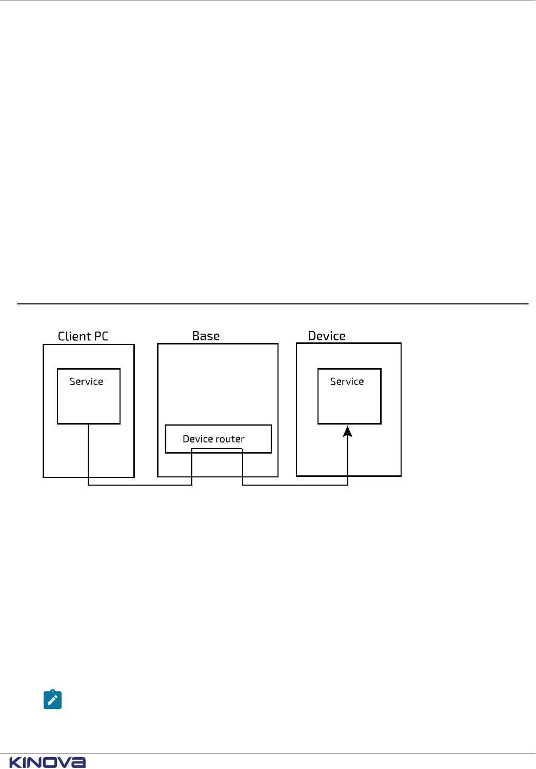
Kinova® Gen3 Ultra lightweight robot User Guide 180
• user: admin
• password: admin
A session is opened using a SessionManager object.
Sessions and robot control
Multiple users can connect to the same robot simultaneously, and have multiple sessions open on
the robot.
A session must be created before commands can be received by the base (otherwise they will be
discarded). Sessions are only supported for communications routed through the base. Sessions are
not supported for communications between a client computer and a device (i.e. low-level bypass
servoing).
Currently, high-level servoing for the robot only work in single-level servoing mode. Multi-level
servoing is not currently supported. What this means is that multiple sessions can be active on
the robot, and multiple users can pull data from the robot. However, only one session can actively
control the robot at any given time. Rules are in place on the robot base to manage which session
has control of the robot at any given time.
Device routing and transport
This section describes the concept of device routing and low-level transport.
Figure 79: Device routing
The API allows you to communicate with the robot devices. Using a device identifier the RPCs and
pub/sub methods of the API are routed by the robot base and directly bridged to the intended
device.
The routing from the client computer, through the base to a device is managed by a
RouterClient object in the API. A Session on the robot depends on a RouterClient object.
RouterClient objects depend, for low-level details of the transport of the routed methods, on
Transport objects. A Transport object uses a specific underlying network transport protocol.
The API defines two types of Transport objects, one using TCP as the protocol, and another using
UDP.
TCP Transport objects are used for high-level robot control and configuration.
UDP Transport object are used for low-level (real-time) cyclic communication with the robot.
Note: Since Sessions require a RouterClient, and a RouterClient is tied to a
Transport object using a specific protocol, separate Sessions must be created if high-level
control / configuration and low-level control are used in the same application.
+1 514-277-3777 kinovarobotics.com
© 2022 Kinova inc. All rights reserved.
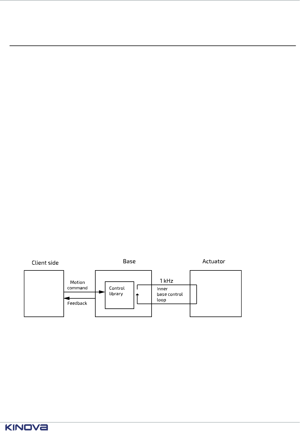
Kinova® Gen3 Ultra lightweight robot User Guide 181
For more details, see the API documentation on GitHub.
Robot servoing modes
This section describes the concept of servoing modes on the robot.
There are multiple servoing modes on the robot. A servoing mode is a modality through which
commands are transmitted to robot devices during operation. Depending on the servoing mode
chosen, the details involved in controlling via the API will be different.
There are two servoing modes:
• High-level
• Low-level
• Low-level bypass
High-level servoing
This section describes the concept of high-level servoing with the robot.
High-level servoing is the default servoing mode for the robot on bootup.
In high-level servoing, users connect to the base through the API (whether directly, or through
the Web App built on top of the API), sending command inputs. The base routes commands to the
actuators, and manages a 1 kHz control loop.
High-level servoing is the recommended servoing mode for non-advanced users.
High-level servoing allows a client to control the robot by sending it a target (angular or Cartesian)
position or velocity via an API method which is sent once (i.e. no high frequency client-controlled
communication between the client PC and the robot). High level API calls are redirected to the
robot control library to calculate inverse kinematics (breaking down the command into commands
for actuators) and apply limits (protection zones, singularity management, self-collision avoidance).
The base then manages the execution of the command via the 1 kHz communications with the
actuators.
Figure 80: High-level servoing
High-level servoing is the default servoing mode for the robot on bootup. In high-level servoing,
users connect to the base through the API (whether directly, or through the Web App built on top
of the API), sending command inputs. The base routes commands to the actuators, and manages a 1
kHz control loop.
High-level servoing is the recommended servoing mode for non-advanced users. High-level
servoing allows a client to control the robot by sending it a target (angular or Cartesian) position
or velocity via an API method which is sent once (i.e. no high frequency client-controlled
communication between the client PC and the robot).
+1 514-277-3777 kinovarobotics.com
© 2022 Kinova inc. All rights reserved.
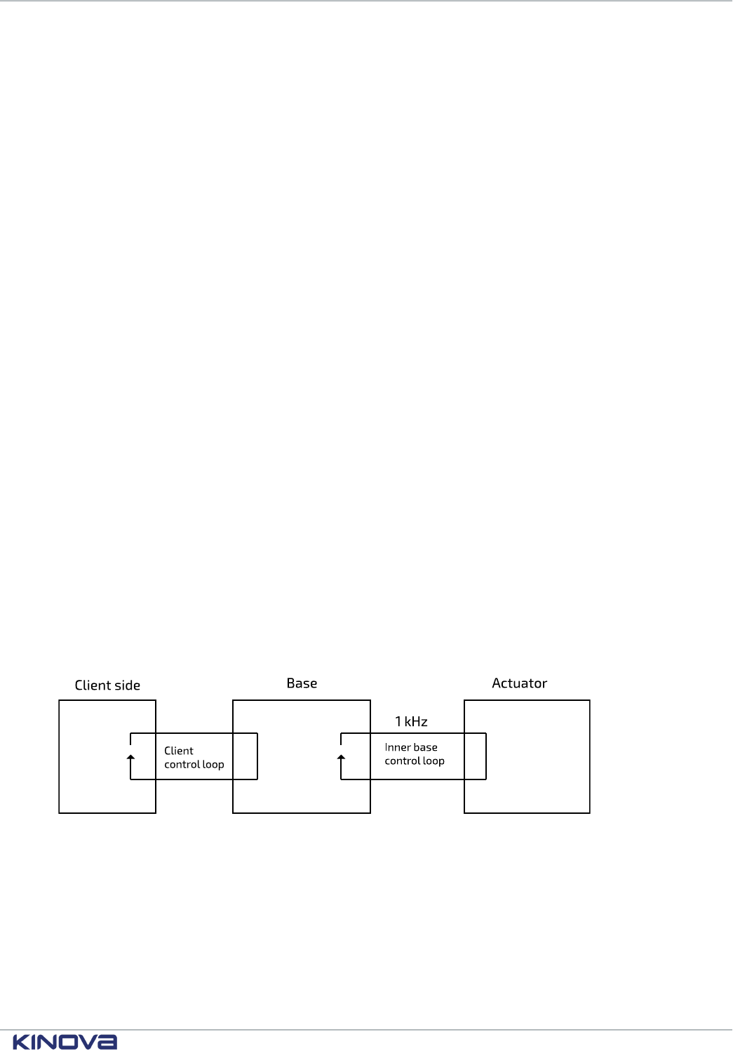
Kinova® Gen3 Ultra lightweight robot User Guide 182
High level API calls are redirected to the robot control library to calculate inverse kinematics
(breaking down the command into commands for actuators) and apply limits (protection zones,
singularity management, self-collision avoidance).
The base then manages the execution of the command via the 1 kHz communications with the
actuators.
Low-level servoing offer lighter and faster API methods, but at the cost of having to manage these
details yourself.
Sessions and control permissions
As soon as someone takes control of the robot by sending a control command (whether from API
calls, Web App session, or Xbox gamepad input) to the robot, the control mode changes from IDLE
to SERVOING. In this mode, control commands from other sessions sent via the Web App or API
methods will be blocked while the control mode is in SERVOING and this session has control.
However, after a predefined "grace period" of 7.5 seconds elapses with no new control commands
from the user, the robot control mode returns to IDLE and someone else can take control by
sending control inputs via the Web App or API calls.
Override by physical controls
Physical controls of the robot via a connected Xbox gamepad or the buttons on the robot wrist
override user session control of the robot via Web App or API calls. These physical controls always
take precedence immediately, without having to wait for the grace period to elapse.
Low-level servoing
This section describes the concept of low-level servoing with the robot.
In low-level servoing, the API client connects to the base and sends commands through the base for
routing.
The base ensures device routing and internal communications with the actuators at 1 kHz, but the
high-level functionalities for the base control loop (robot kinematics, trajectory management, etc.)
are no longer available.
Low-level servoing allows clients to control each actuator individually by sending command
increments at 1 kHz frequency (bypassing the kinematic control library).
Figure 81: Low-level servoing
Low-level bypass servoing
This section describes the concept of low-level bypass servoing for the robot.
In this mode, the client PC uses UDP communication directly with the different actuators - there
is no device routing involved. The client PC is able to communicate directly with the actuators
using their IP addresses. Since the control here bypasses the base completely, the client is fully
responsible for managing the control loop.
+1 514-277-3777 kinovarobotics.com
© 2022 Kinova inc. All rights reserved.
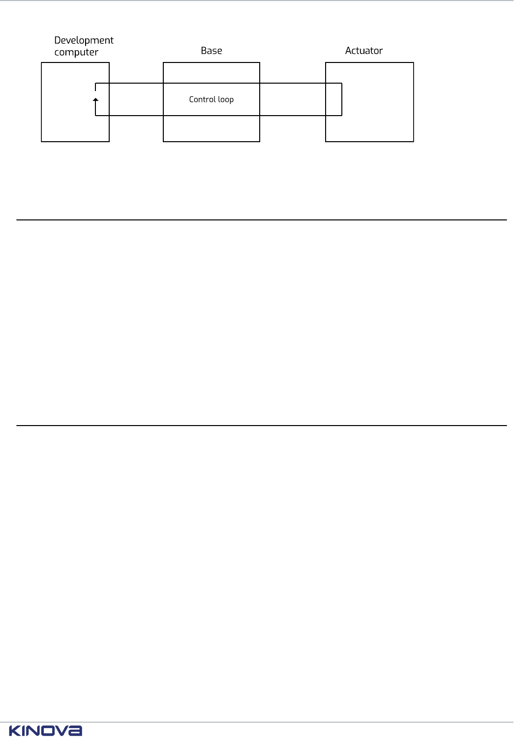
Kinova® Gen3 Ultra lightweight robot User Guide 183
Figure 82: Low-level bypass servoing
Low-level and low-level bypass servoing offer lighter and faster API methods, but at the cost of
having to manage these details yourself.
Notifications
This section describes the concept of notifications in the API.
The robot base can provide notifications on different topics as requested by a client application that
has a session open with the robot.
The robot base uses a Publish/Subscribe design pattern. That is, rather than needing to poll
periodically for updates, the client application subscribes to a list of Topics. Whenever a change
happens related to that topic, whether caused by the same client session, or another, a publisher
sends a notification to all subscribers. Notifications are surfaced to clients via the API, and are also
displayed in the Notifications page of the Web app.
Client applications can also unsubcribe from a topic.
Methods for subscribing and unsubscribing from notification topics are descrcibed in the API
documentation on the Kinova
®
Kortex™ GitHub respository.
Error management
This section describes the concept of error management with the robot.
When an API method is called, sometimes an error will result.
There are three main categories of errors:
• Protocol server errors
• Protocol client errors
• Device errors
The first two categories of errors include all errors relating to the the internal communication
protocol. (ex: invalid, unsupported or unknown calls, out of session call, etc.)
The other category is for errors coming from the target device.
For each high level category, there are also more detailed and specific errors.
For more information about the error codes that can be produced, see the Kinova
®
Kortex™ GitHub
documentation.
Error codes
This section describes the meaning of error codes used by the API.
+1 514-277-3777 kinovarobotics.com
© 2022 Kinova inc. All rights reserved.
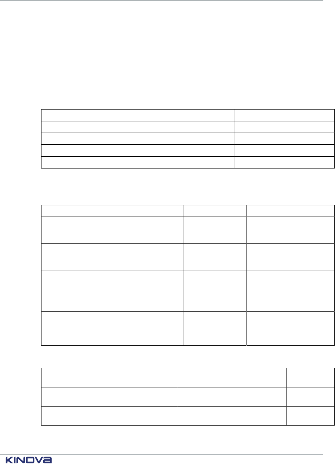
Kinova® Gen3 Ultra lightweight robot User Guide 184
Overview
Some API calls will result in errors. When an error occurs, an exception is thrown which includes
information about the type of error.
The error information includes at minimum an Error Code and a Sub-Error code.
The error code identifies the general type of error, while the sub-error code provides more detailed
information.
The following reference tables provide guidance in interpreting error codes.
Error codes description
Name Description
SUCCESS No errors
ERROR_PROTOCOL_SERVER Protocol buffer server error
ERROR_PROTOCOL_CLIENT Protocol buffer client error
ERROR_DEVICE Device error
Sub-Error codes description
Table 80: General (used when there are no more specific error codes available)
Name Description Why is error reported?
SUB_SUCCESS No errors Sub-error code is set to
sub-success when error
code is set to success
FAILED Failure Used to report an error
for which there is no more
specific sub-error code
UNIMPLEMENTED Unimplemented
method
Reports back that the
remote procedure call
is not implemented on
the robot, though it is
available through the service
INVALID_PARAM Invalid parameter The remote procedure call is
supported, but parameter is
considered invalid by the robot
(i.e. outside admissible range)
Table 81: Protocol Server (reported by the protocol server)
Name Description Where is error
reported?
UNSUPPORTED_SERVICE Service not recognized
by protocol server
Rx side
UNSUPPORTED_METHOD Function not recognized
by protocol server
Rx side
+1 514-277-3777 kinovarobotics.com
© 2022 Kinova inc. All rights reserved.

Kinova® Gen3 Ultra lightweight robot User Guide 185
Name Description Where is error
reported?
TOO_LARGE_ENCODED_FRAME_BUFFER Encoded frame larger than
what transport permits
Tx side
TOO_LARGE_ENCODED_PAYLOAD_BUFFER Encoded payload is larger
than what transport permits
FRAME_ENCODING_ERR Unable to encode frame Tx side
FRAME_DECODING_ERR Unable to decode frame Rx side
INCOMPATIBLE_HEADER_VERSION Frame header version differs from
what is expected by protocol server
Rx side
UNSUPPORTED_FRAME_TYPE Frame type not recognized
by protocol server
Rx side
UNREGISTERED_NOTIFICATION_RECEIVED Protocol server receiving
unregistered notification
PAYLOAD_DECODING_ERR Unable to decode payload
INVALID_SESSION Session not recognized
by protocol server
Rx side
INVALID_DEVICE Device ID when bridging is
not found or already in use.
Table 82: Protocol Client (reported by the protocol client)
Name Description Where is error
reported?
TOO_LARGE_ENCODED_FRAME_BUFFER Encoded frame larger than
what transport permits
Tx side
TOO_LARGE_ENCODED_PAYLOAD_BUFFER Encoded payload is larger
than what transport permits
FRAME_ENCODING_ERR Unable to encode frame Tx side
FRAME_DECODING_ERR Unable to decode frame Rx side
INCOMPATIBLE_HEADER_VERSION Frame header version differs from
what is expected by protocol client
Rx side
UNSUPPORTED_FRAME_TYPE Received frame type is not recognized
by the protocol client (or unexpected,
unknown, or unsupported)
Rx side
UNREGISTERED_NOTIFICATION_RECEIVED Protocol client received notification
for which it does not have a
registered notification to call back
PAYLOAD_DECODING_ERR Unable to decode payload
UNREGISTERED_FRAME_RECEIVED Client received a response that it
was not expecting (i.e. for which it
did not send a remote procedure call)
Robot - the following are sub-error codes that can be reported by the robot
+1 514-277-3777 kinovarobotics.com
© 2022 Kinova inc. All rights reserved.
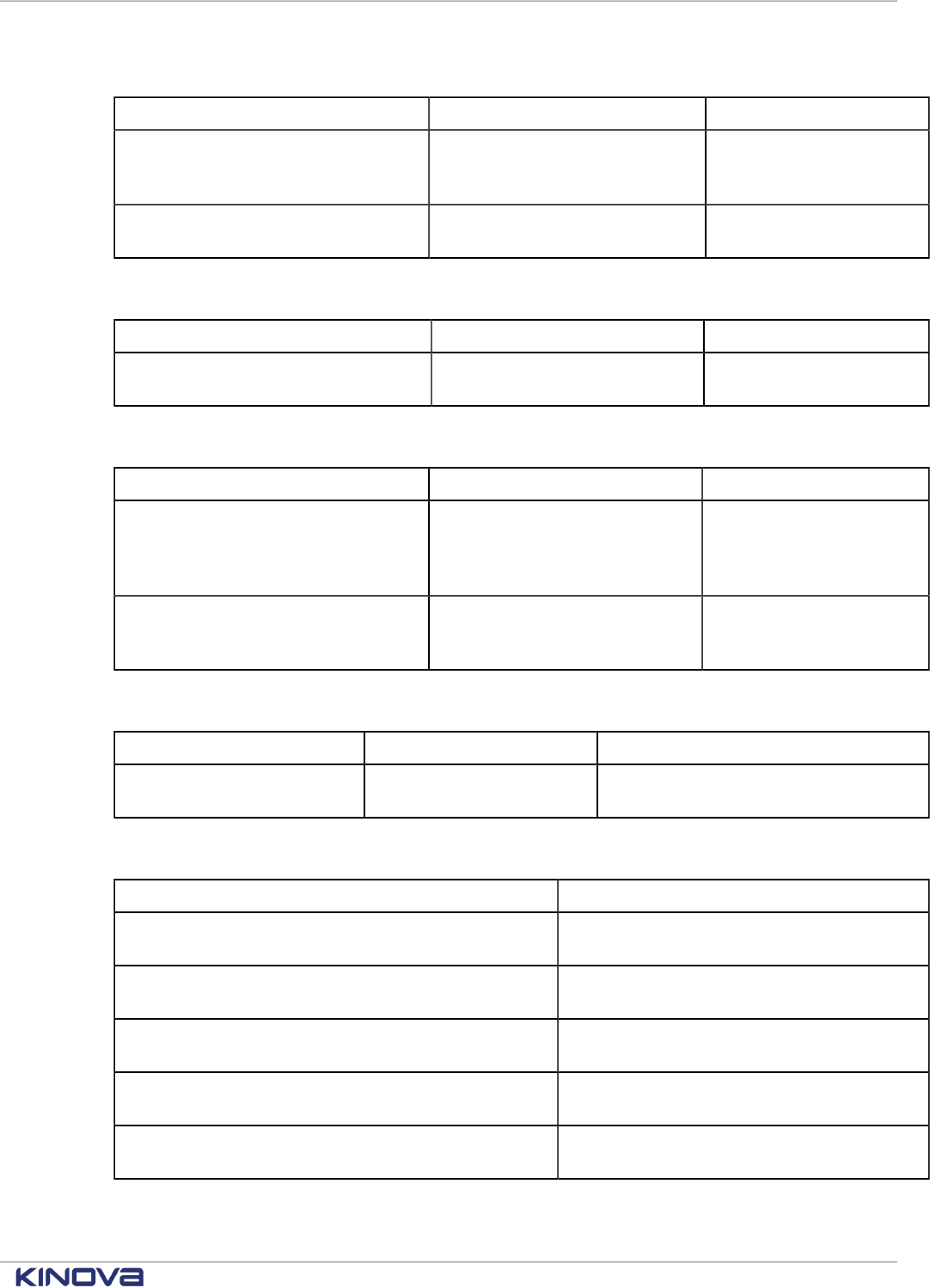
Kinova® Gen3 Ultra lightweight robot User Guide 186
Table 83: Session / users
Name Description When is error reported?
INVALID_PASSWORD Password does not
match specified user
createSession(),
changePassword()
function calls
USER_NOT_FOUND Unrecognized user createSession()
function call
Table 84: Configuration
Name Description When is error reported?
ENTITY_NOT_FOUND Operation failed because
could not retrieve entity
readX(), updateX(), and
deleteX() function calls
Table 85: Control / sequence
Name Description When is error reported?
ROBOT_MOVEMENT_IN_PROGRESS When robot refuses the new
control command because
robot movement is in progress
executeAction(),
playX(), sendTwistX(),
sendWrenchX()
function calls
ROBOT_NOT_MOVING When attempting to
stop a robot movement
when it is not yet moving
stopAction(), stop(),
pause(), pauseAction()
function calls
Table 86: Configuration backup
Name Description When is error reported?
NO_MORE_STORAGE_SPACE Unable to execute action
because no storage left
createConfigurationBackup()
function call
Table 87: Operating mode
Name Description
ROBOT_NOT_READY When sending a command while the
robot initialization is not complete
ROBOT_IN_FAULT When sending a command
while the robot is in a fault
ROBOT_IN_MAINTENANCE When sending a command while
the robot is in maintenance
ROBOT_IN_UPDATE_MODE When sending a command
while the robot is in update
ROBOT_IN_EMERGENCY_STOP When the robot was manually
put into an emergency stop
+1 514-277-3777 kinovarobotics.com
© 2022 Kinova inc. All rights reserved.
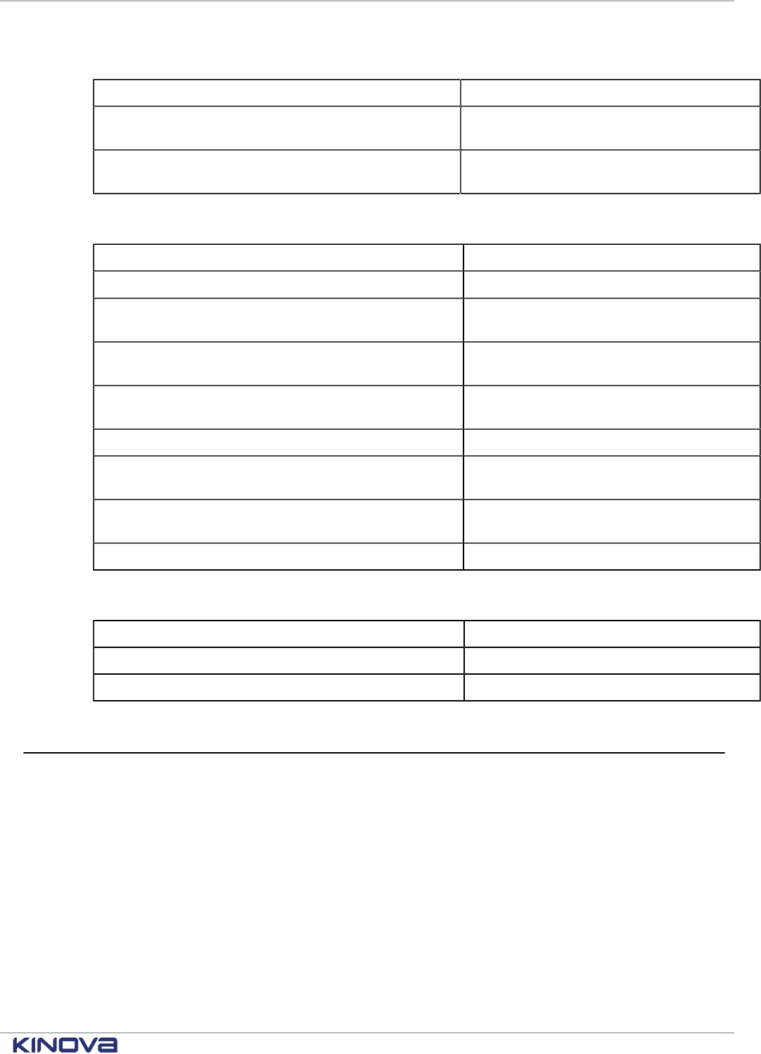
Kinova® Gen3 Ultra lightweight robot User Guide 187
Table 88: Servoing
Name Description
SINGLE_LEVEL_SERVOING A second client is attempting to control the
robot while it is in single-level servoing mode
LOW_LEVEL_SERVOING Attempting to send high-level control to the
robot while it is in low-level servoing mode
Table 89: Mapping
Name Description
MAPPING_GROUP_NON_ROBOT Trying to add non-root MapGroup to Mapping
MAPPING_INVALID_GROUP Trying to add invalid or non-
existent MapGroup to Mapping
MAPPING_INVALID_MAP Trying to add invalid or non-
existent Map to Mapping
MAP_GROUP_INVALID_MAP Trying to add invalid or non-
existent Map to MapGroup
MAP_GROUP_INVALID_PARENT Trying to add MapGroup under invalid parent
MAP_GROUP_INVALID_CHILD Trying to add invalid or non-
existent child to MapGroup
MAP_GROUP_INVALID_MOVE Trying to change MapGroup's
parent: move not supported
MAP_IN_USE Deleting a Map used in Mapping or MapGroup
Table 90: Network
Name Description
WIFI_CONNECT_ERROR Unable to connect to Wi-Fi network
UNSUPPORTED_NETWORK_TYPE Unsupported network type
Kinova
®
Kortex™ GitHub repository
This section describes the contents of the Kinova
®
Kortex™ GitHub repository.
For more detailed information about developing applications using the API visit the Kinova
®
Kortex™ GitHub repository at: github.com/kinovarobotics/kortex
The repository offers access to a number of resources for developers.
• setup instructions and release notes
• detailed API documentation by language
• code examples
+1 514-277-3777 kinovarobotics.com
© 2022 Kinova inc. All rights reserved.

Kinova® Gen3 Ultra lightweight robot User Guide 188
Kinova
®
Kortex™ ROS packages and GitHub repository overview
This section describes the contents of the ROS packages for the robot (and all other products enabled by
Kinova
®
Kortex™).
Introduction
Kinova
®
Kortex™ ROS is the official repository containing ROS packages to interact with Kortex
and related products. It consists of a number of ROS packages built on top of the client Kortex API.
These ROS packages are designed to work with ROS Melodic Morenia and ROS Noetic Ninjemys.
ROS Melodic is compatible with Ubuntu 18.04 (Bionic)
Methods provided by the underlying API are offered as ROS services and topics, depending on the
method.
• RPC methods are exposed via ROS services
• pub/sub methods are exposed via ROS topics
The ROS Messages correspond to the message type definitions of the underlying API.
The ROS interface can be accessed using either Python (rospy) or C++ (roscpp).
Support is included for Gazebo and MoveIt.
Detailed documentation of the packages is available on the Kinova ros_kortex GitHub
repository at github.com/kinovarobotics/ros_kortex
The repository includes various packages related to ROS development:
• setup instruction and release notes
• kortex_api (package containing header files and libraries needed to use the C++ Kortex API)
• kortex_control (package contains configuration files for the ros_control controllers used to
control the simulated robot
• kortex_description (package contains URDF and STL files of the robot)
• kortex_driver (ROS node package to allow direct communication with the robot base)
• kortex_examples (examples needed to understand the basics of ros_kortex)
• kortex_gazebo (package contains files to simulate the robot)
• kortex_moveit_config (contains all the auto-generated MoveIt! configuration ROS
packages)
Important: Low-level control is not available through ROS because ROS is not capable of
handling the required 1 kHz communication rate.
Kinova
®
Kortex™ MATLAB
®
API and GitHub repository overview
Describes the contents of the Kinova
®
Kortex™ MATLAB API and GitHub repository.
The Kinova
®
Kortex™ MATLAB
®
API provides a wrapper giving access, via MATLAB
®
and
Simulink
®
to a subset of the Kortex API functionality.
The package also includes integration of the vision module with the MATLAB
®
Image Acquisition
Toolbox™.
This package has been tested on Ubuntu 16.04 (64-bit) and Windows 10.
+1 514-277-3777 kinovarobotics.com
© 2022 Kinova inc. All rights reserved.

Kinova® Gen3 Ultra lightweight robot User Guide 189
More detailed information is available on the matlab_kortex GitHub repository at github.com/
kinovarobotics/matlab_kortex.
Working with camera streams using GStreamer
The vision module camera streams can be processed programmatically using the GStreamer framework.
GStreamer offers a pipeline-base framework for image-processing.
GStreamer
Kinova recommends that developers use the GStreamer framework for handling the camera's
sensor streams. GStreamer offers a pipeline-based framework that allows you to link together
plugins for image-processing workflows.
Requirements:
• GStreamer version: 1.8.3 and above
• Supported operating systems:
º Windows 7 and later
º Ubuntu 16.04 and later
Using GStreamer
GStreamer pipelines can be called from the command line using the gst-launch-1.0 utility.
For integration with applications, GStreamer offers a number of language bindings, which include
both C++ and Python.
Official documentation for the GStreamer framework, including installation instructions,
application development guidance, and tutorials can be accessed here: https://
gstreamer.freedesktop.org/documentation/
Windows command examples
Examples of using GStreamer with the robot vision module camera streams on the Windows command line.
Color stream CLI example: command to display the color stream
gst-launch-1.0.exe rtspsrc location=rtsp://192.168.1.10/color
latency=30 ! rtph264depay ! avdec_h264 ! autovideosink
Unpacking the example:
• gst-launch-1.0.exe: launch GStreamer
• rtspsrc location=rtsp://192.168.1.10/color latency=30: connect to the RTSP
server at the color stream URL with latency of 30 ms.
• rtph264depay: Extract H.264 video payload from RTP packets
• avdec_h264: decode H.264 video
• autovideosink: search computer registry for video sink (player) and plays decoded video
stream.
Depth stream CLI example: command to display the depth stream
gst-launch-1.0.exe rtspsrc location=rtsp://192.168.1.10/depth
latency=30 ! rtpgstdepay ! videoconvert ! autovideosink
Unpacking the example:
• gst-launch-1.0.exe: launch GStreamer
+1 514-277-3777 kinovarobotics.com
© 2022 Kinova inc. All rights reserved.

Kinova® Gen3 Ultra lightweight robot User Guide 190
• rtspsrc location=rtsp://192.168.1.10/depth latency=30: connect to the RTSP
server at the color stream URL with latency of 30 ms.
• rtpgstdepay: extract GStreamer buffers from RTP packets
• videoconvert: automatically convert the video to a format understandable to the chosen
video sink in the next step
• autovideosink: search computer registry for video sink (player) and plays decoded video
stream.
Linux command examples
Examples of using GStreamer with the robot vision module camera streams on the Linux command line.
Color stream CLI example: command to display the color stream
gst-launch-1.0 rtspsrc location=rtsp://192.168.1.10/color latency=30 !
rtph264depay ! avdec_h264 ! autovideosink
Unpacking the example:
• gst-launch-1.0: launch GStreamer
• rtspsrc location=rtsp://192.168.1.10/color latency=30: connect to the RTSP
server at the color stream URL with latency of 30 ms.
• rtph264depay: extract H.264 video payload from RTP packets
• avdec_h264: decode H.264 video
• autovideosink: search computer registry for video sink (player) and play decoded video
stream.
Depth stream CLI example: command to display the depth stream
gst-launch-1.0 rtspsrc location=rtsp://192.168.1.10/depth latency=30 !
rtpgstdepay ! videoconvert ! autovideosink
Unpacking the example:
• gst-launch-1.0: launch GStreamer
• rtspsrc location=rtsp://192.168.1.10/depth latency=30: connect to the RTSP
server at the color stream URL with latency of 30 ms.
• rtpgstdepay: extract GStreamer buffers from RTP packets
• videoconvert: automatically convert the video to a format understandable to the chosen
video sink in the next step
• autovideosink: search computer registry for video sink (player) and play decoded video
stream.
Kinova
®
Kortex™ ROS vision module package and Github
overview
Describes the ROS vision module package for the robot.
The Kinova
®
Kortex™ ROS vision module package provides helper methods and launch scripts to
access the Gen3 Ultra lightweight robot vision module depth and color sensor streams within ROS.
For more details, including documentation, see the Kinova ros_kortex_vision GitHub repository at
github.com/kinovarobotics.com/ros_kortex_vision.
+1 514-277-3777 kinovarobotics.com
© 2022 Kinova inc. All rights reserved.
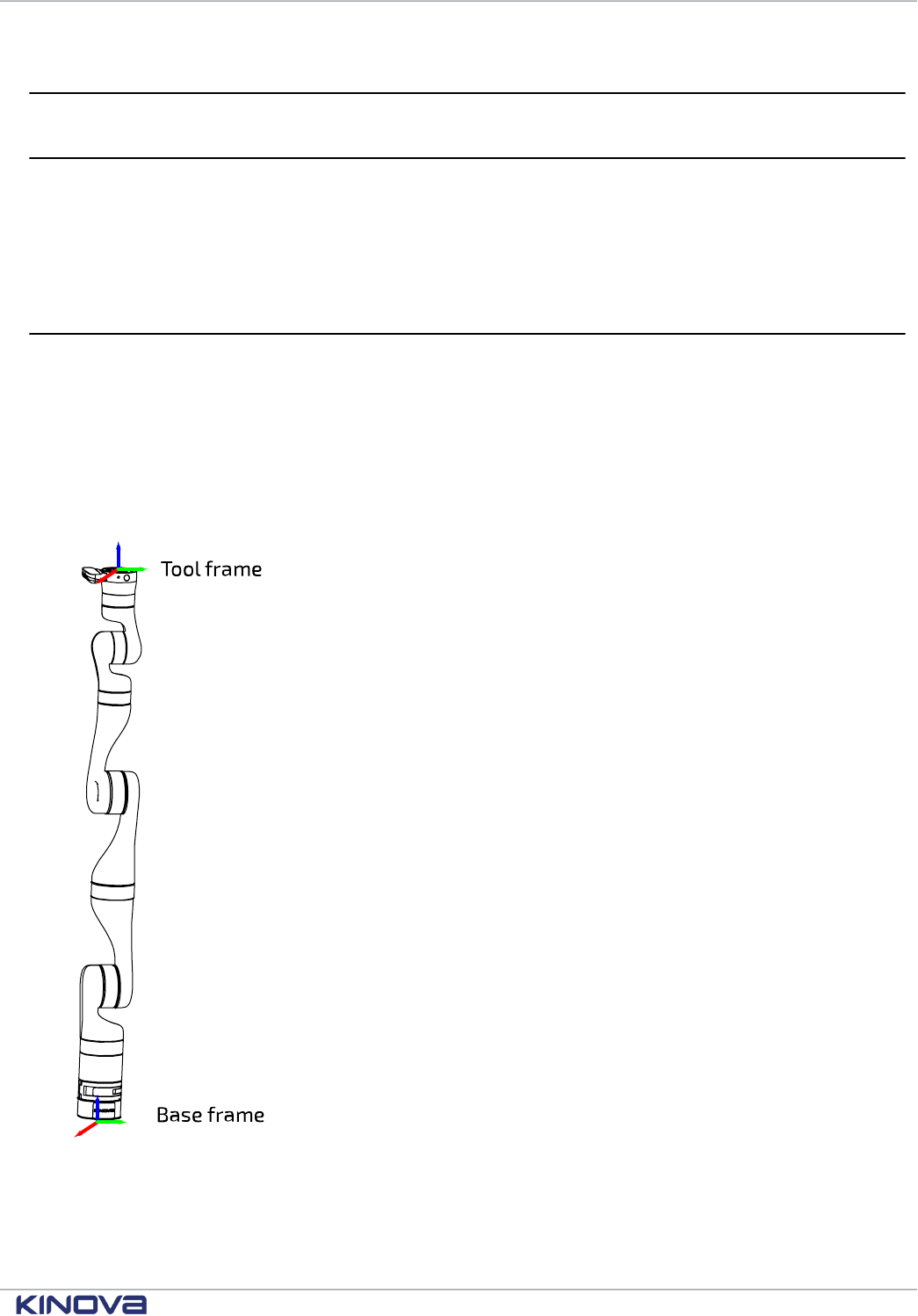
Kinova® Gen3 Ultra lightweight robot User Guide 191
Guidance for advanced users
Overview
The advanced guidance section gathers together reference information on topics useful to advanced users of
the robot.
Introduction
The following contents are intended for advanced users.
Reference frames and transformations
Standard robot frames
Describes the standard frames of the robotic arm.
The robot has two standard frames:
• base frame (base reference frame)
• rotating frame (actuator 1 reference frame)
• tool frame (end-effector reference frame)
Figure 83: Two standard frames
Different control modes make use of different frames.
+1 514-277-3777 kinovarobotics.com
© 2022 Kinova inc. All rights reserved.
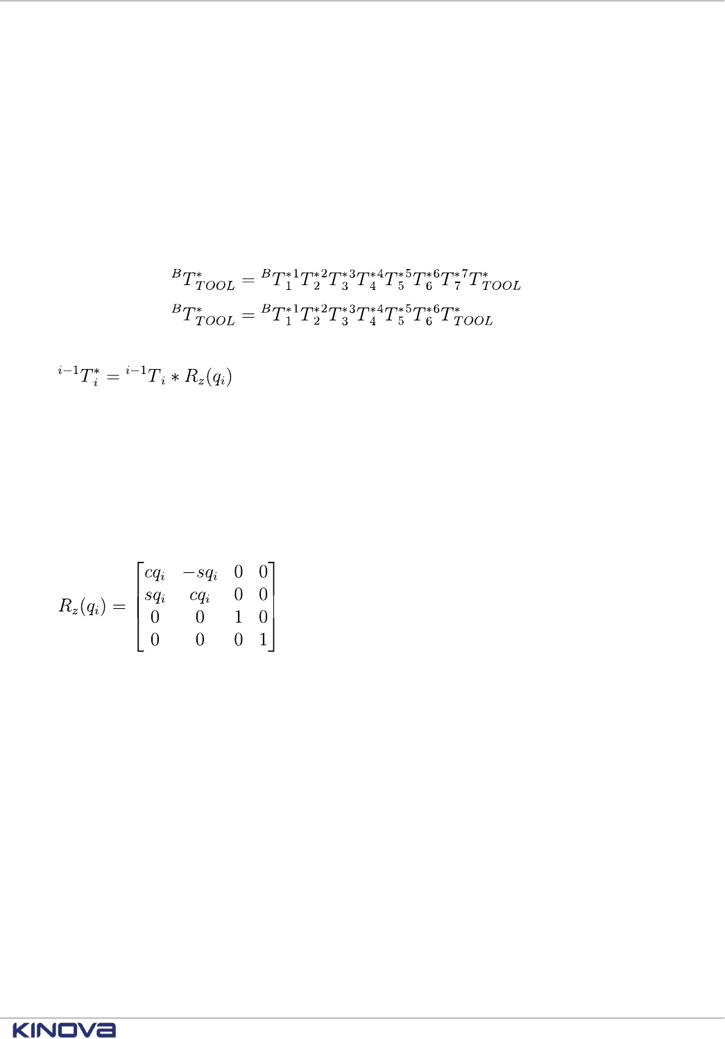
Kinova® Gen3 Ultra lightweight robot User Guide 192
Homogeneous transforms
Homogeneous transforms for the robot are provided. Homogeneous transforms define transformations
between successive reference frames in the robot, allowing coordinates in one frame to be expressed in
terms of another.
Introduction
The forward kinematics of the robot are determined by homogeneous transform matrices. These
matrices represent the transformations from one frame (base, joint, or interface) to the next along
the kinematic chain. These transformations allow for the coordinates in one frame to be expressed
in terms of another.
The overall transformation from the base frame to the tool frame is given by:
For 7 DoF robot:
For 6 DoF robot:
Here:
Where:
i-1
T
*
i
is the matrix for the general transformation matrix from frame [i-1] to frame [i].
i-1
T
i
is the transform from the previous frame [i-1] to the current frame [i] when q
i
, the angle for
joint i, is 0 (Here, q
i
is the angle in radians).
R
z
(q
i
) is the transformation matrix for a rotation of q
i
around joint i (the z axis for the joint frame is
always defined to be along the joint axis of rotation.):
cq
i
= cos(q
i
) and sq
i
= sin(q
i
)
Homogeneous transform matrices - 7 DoF spherical wrist
Homogeneous transform matrices for the 7 DoF spherical wrist robot.
+1 514-277-3777 kinovarobotics.com
© 2022 Kinova inc. All rights reserved.
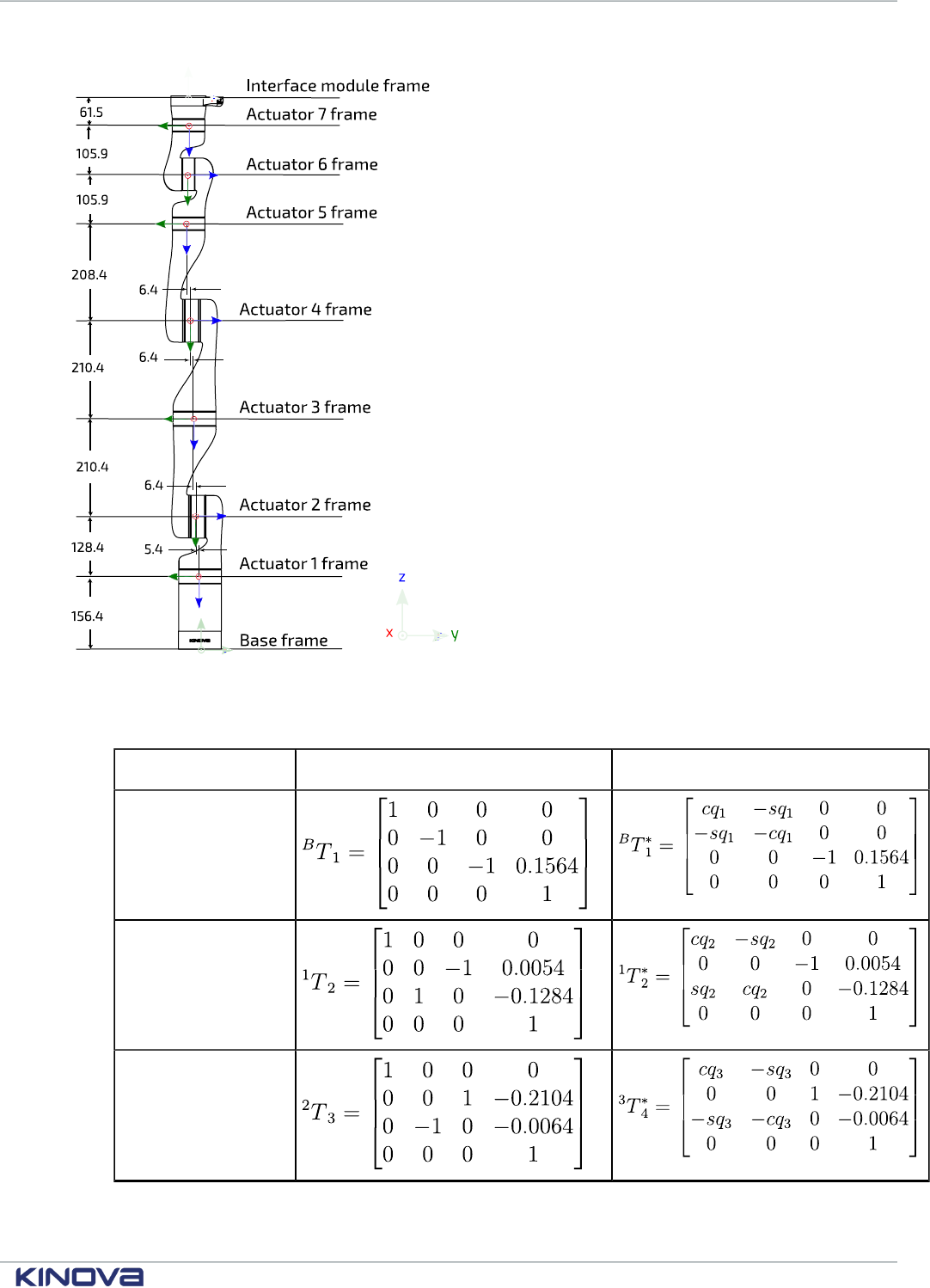
Kinova® Gen3 Ultra lightweight robot User Guide 193
Figure 84: 7DoF robot frame definitions and dimensions (all joints at 0 position, dimensions in mm)
Table 91: 7 DoF homogeneous transformation matrices
Transformation
i-1
T
i
i-1
T
*
i
Base to frame 1
Frame 1 to frame 2
Frame 2 to frame 3
+1 514-277-3777 kinovarobotics.com
© 2022 Kinova inc. All rights reserved.
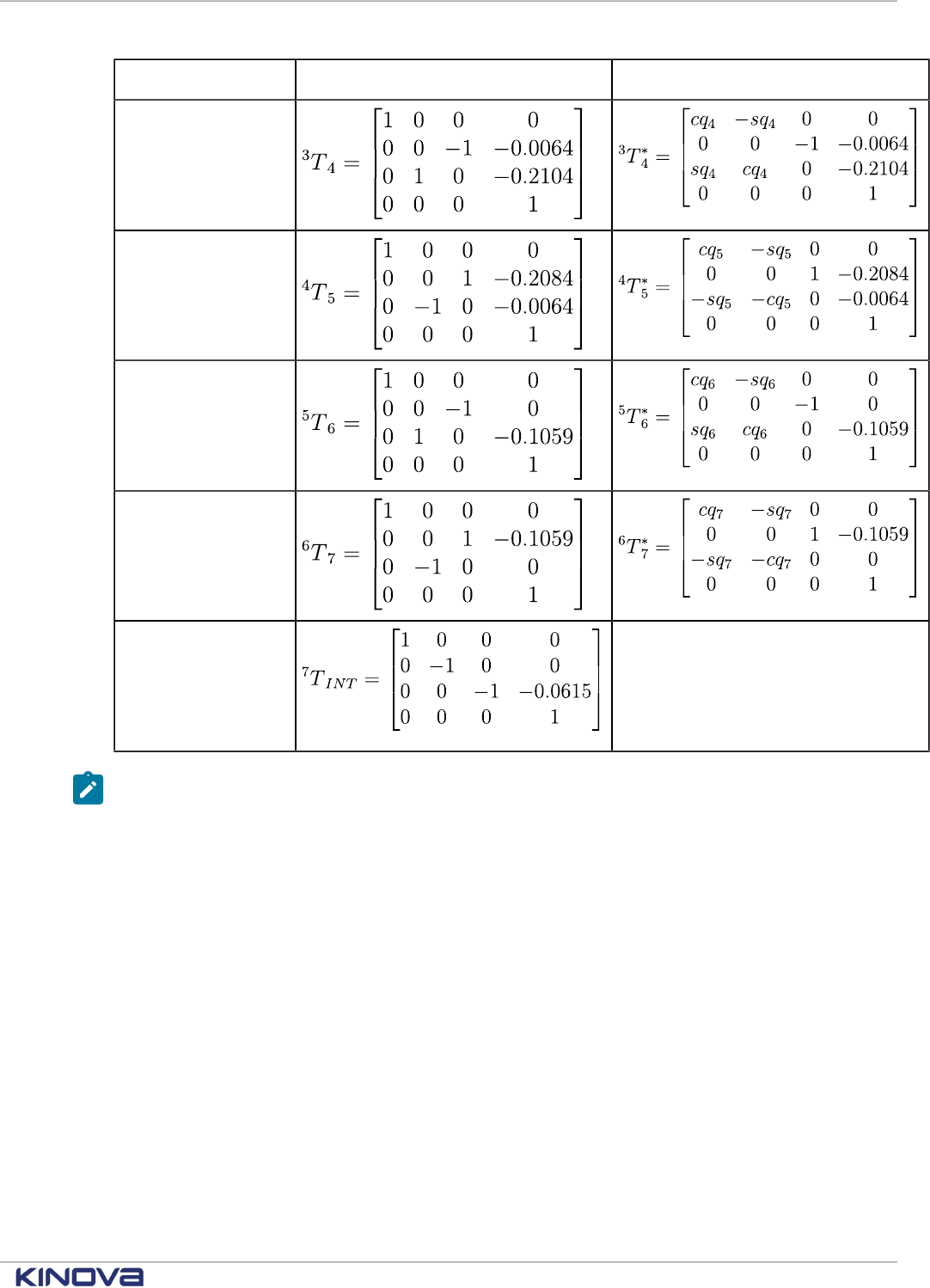
Kinova® Gen3 Ultra lightweight robot User Guide 194
Transformation
i-1
T
i
i-1
T
*
i
Frame 3 to frame 4
Frame 4 to frame 5
Frame 5 to frame 6
Frame 6 to frame 7
Frame 7 to interface
module
Note: units are in meters for homogeneous transform translations in the right-hand column
of each matrix.
Homogeneous transform matrices - 6 DoF spherical wrist
Homogeneous transform matrices for the 6 DoF spherical wrist robot.
+1 514-277-3777 kinovarobotics.com
© 2022 Kinova inc. All rights reserved.
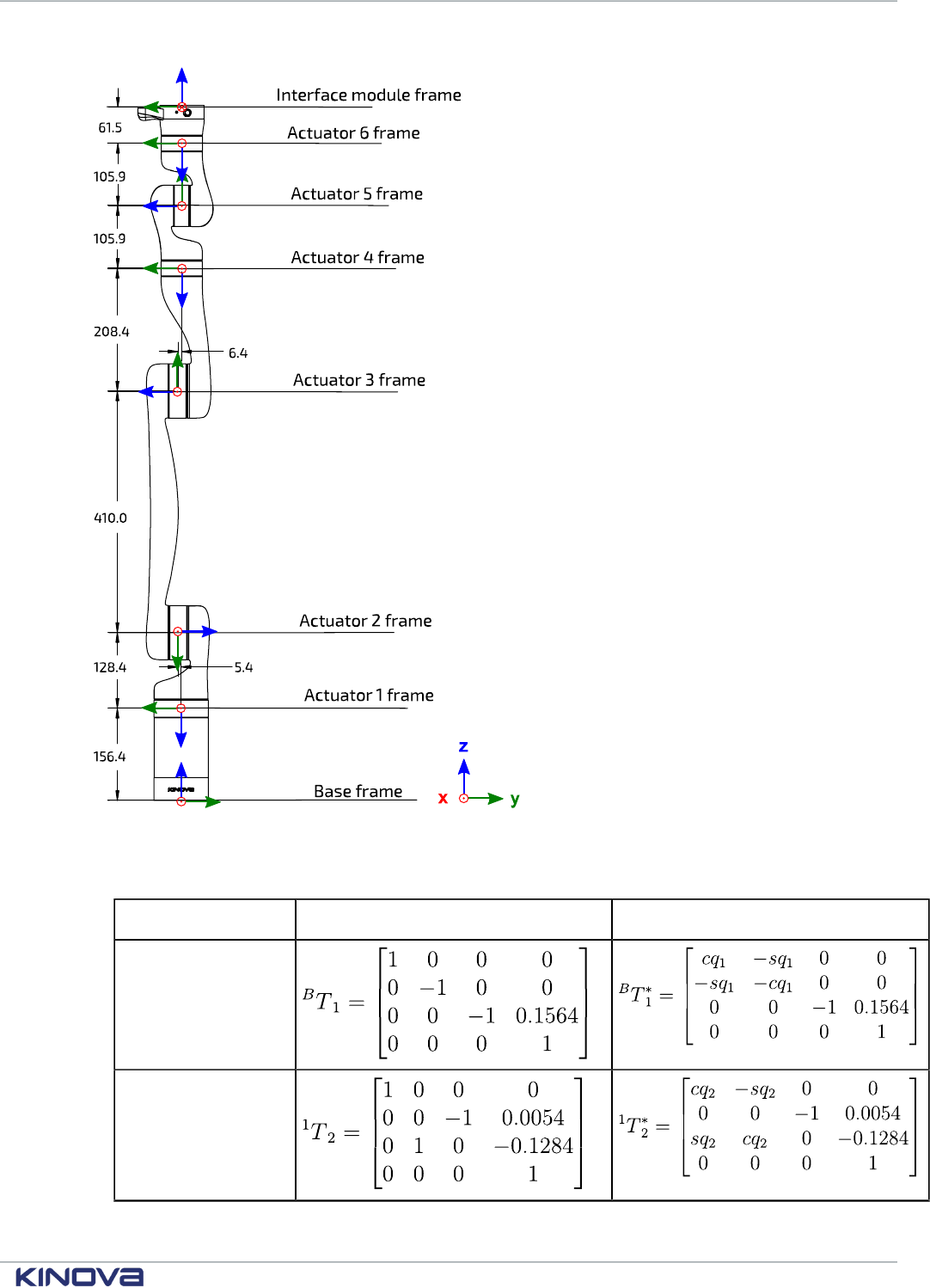
Kinova® Gen3 Ultra lightweight robot User Guide 195
Figure 85: 6 DoF robot frame definitions and dimensions (all joints at 0 position, dimensions in mm)
Table 92: 6 DoF homogeneous transformation matrices
Transformation
i-1
T
i
i-1
T
*
i
Base to frame 1
Frame 1 to frame 2
+1 514-277-3777 kinovarobotics.com
© 2022 Kinova inc. All rights reserved.
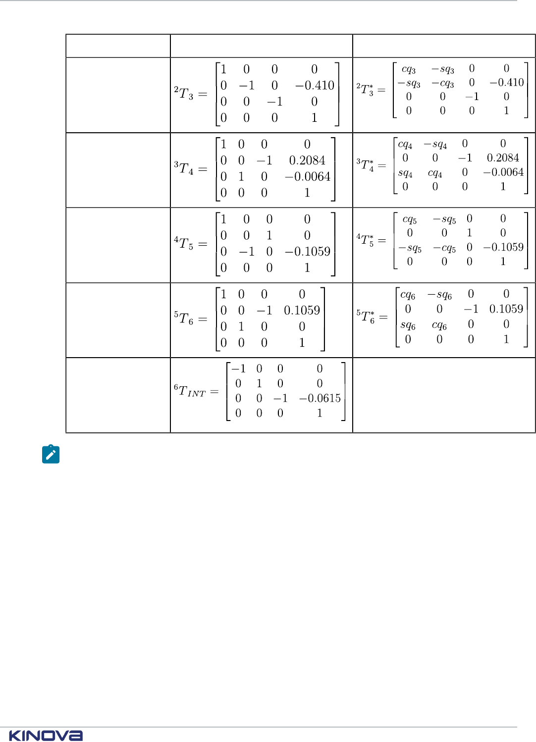
Kinova® Gen3 Ultra lightweight robot User Guide 196
Transformation
i-1
T
i
i-1
T
*
i
Frame 2 to frame 3
Frame 3 to frame 4
Frame 4 to frame 5
Frame 5 to frame 6
Frame 6 to interface
module
Note: units are in meters for homogeneous transform translations in the right-hand column
of each matrix.
Vision module sensors reference frames
Homogeneous transforms defining the reference frames of the video module sensors in terms of the interface
module frame. These are useful in correlating data from the color and depth sensors.
Overview
The vision module captures data about the environment of the robot via two sensors:
• color sensor
• depth sensor
Developing vision applications and vision-based control of the robot will require correlating the
data from these two sensors with each other and with the position of the end effector.
+1 514-277-3777 kinovarobotics.com
© 2022 Kinova inc. All rights reserved.
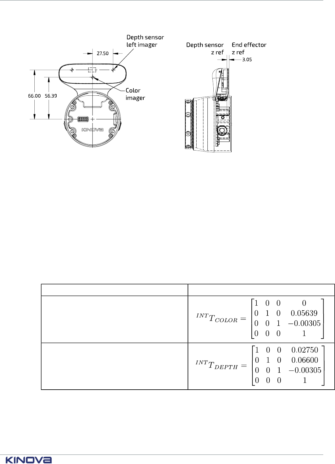
Kinova® Gen3 Ultra lightweight robot User Guide 197
Camera frames
Figure 86: Vision sensors
Color sensor
The reference frame for the color sensor has the same orientation as that of the end effector, but
with an offset of (dx, dy, dz) = (0 mm, 56.39 mm, -3.05 mm).
Depth sensor
The origin for the depth center frame of reference is defined at the center of the left imager,
directly in front of the lens of the left imager. The z offset for the depth sensor reference frame is
the same as for the color sensor reference frame, and the y offset is 66.00 mm. Because the left
imager is used as a reference, there is also an x offset of 27.50 mm.
The matrices for the reference frame transformations from end effector frame to vision sensor
frame are shown in the table below.
Table 93: Reference frame transformations from end effector to sensors (displacement units in meters)
Transformation Transformation matrix
End effector to color sensor
End effector to depth sensor
Denavit-Hartenberg (DH) parameters
DH parameters the robot are provided.
+1 514-277-3777 kinovarobotics.com
© 2022 Kinova inc. All rights reserved.
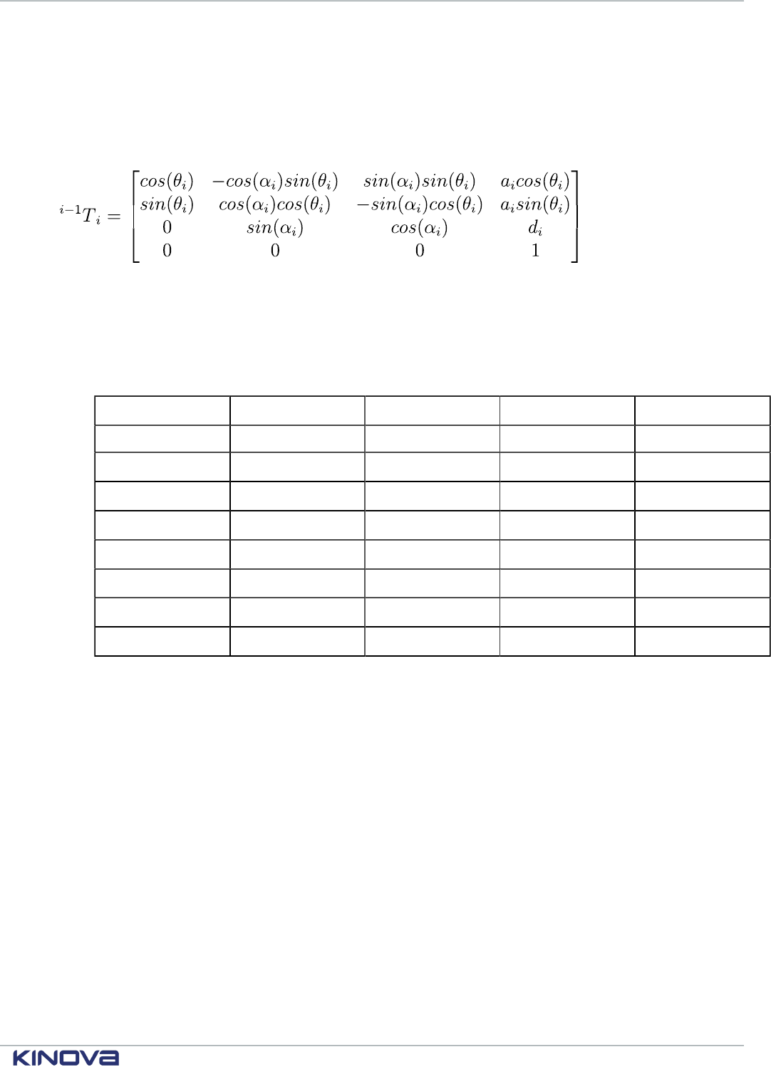
Kinova® Gen3 Ultra lightweight robot User Guide 198
DH parameters
Denavit-Hartenberg (DH) parameters offer another convenient way to specify the reference frame
transformations for the robot kinematic chain.
The Classical DH parameters convention transformation expresses a frame in terms of the previous
as:
Figure 87: DH parameters Classical frames transformations
Denavit-Hartenberg (DH) parameters - 7 DoF spherical wrist
DH parameters for the 7 DoF spherical wrist robot.
Table 94: 7 DoF spherical Classical DH parameters
i α
i
(radians) a
i
(m) d
i
(m) θ
i
(radians)
0 (from base) π 0.0 0.0 0
1 π/2 0.0 - (0.1564 + 0.1284) q
1
2 π/2 0.0 - (0.0054 + 0.0064) q
2
+ π
3 π/2 0.0 - (0.2104 + 0.2104) q
3
+ π
4 π/2 0.0 - (0.0064 + 0.0064) q
4
+ π
5 π/2 0.0 - (0.2084 + 0.1059) q
5
+ π
6 π/2 0.0 0.0 q
6
+ π
7 (to interface) π 0.0 - (0.1059 + 0.0615) q
7
+ π
Here q
1
, q
2
... refers to the joint angles.
The figures in the chart are based on the following frames definitions:
+1 514-277-3777 kinovarobotics.com
© 2022 Kinova inc. All rights reserved.
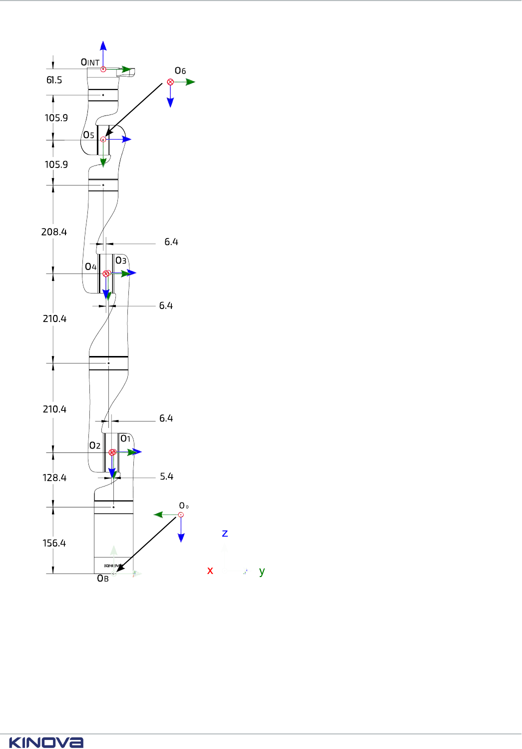
Kinova® Gen3 Ultra lightweight robot User Guide 199
Figure 88: Denavit-Hartenberg frames definitions
Denavit-Hartenberg (DH) parameters - 6 DoF spherical wrist
DH parameters for the 6 DoF spherical wrist robot.
+1 514-277-3777 kinovarobotics.com
© 2022 Kinova inc. All rights reserved.
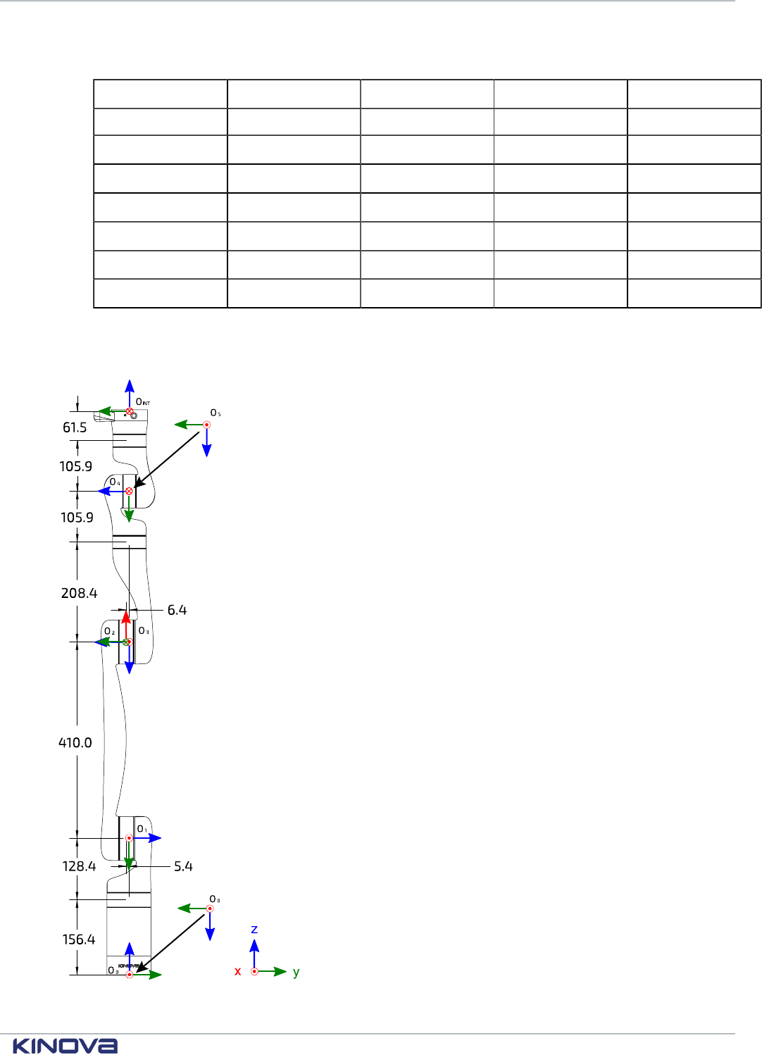
Kinova® Gen3 Ultra lightweight robot User Guide 200
Table 95: 6 DoF spherical Classical DH parameters
i α
i
(radians) a
i
(m) d
i
(m) θ
i
(radians)
0 (from base) 0.0 0.0 π 0.0
1 0.0 -(156.43 + 128.38) π/2 q
1
2 410.0 -5.38 π q
2
- π/2
3 0.0 -6.38 π/2 q
3
- π/2
4 0.0 -(208.43+105.93) π/2 q
4
+ π
5 0.0 0.0 π/2 q
5
+ π
6 (to interface) 0.0 -(105.93+61.53) π q
6
+ π
Here q
1
, q
2
... refers to the joint angles.
The figures in the chart are based on the following frames definitions:
Figure 89: Denavit-Hartenberg frames definitions
+1 514-277-3777 kinovarobotics.com
© 2022 Kinova inc. All rights reserved.
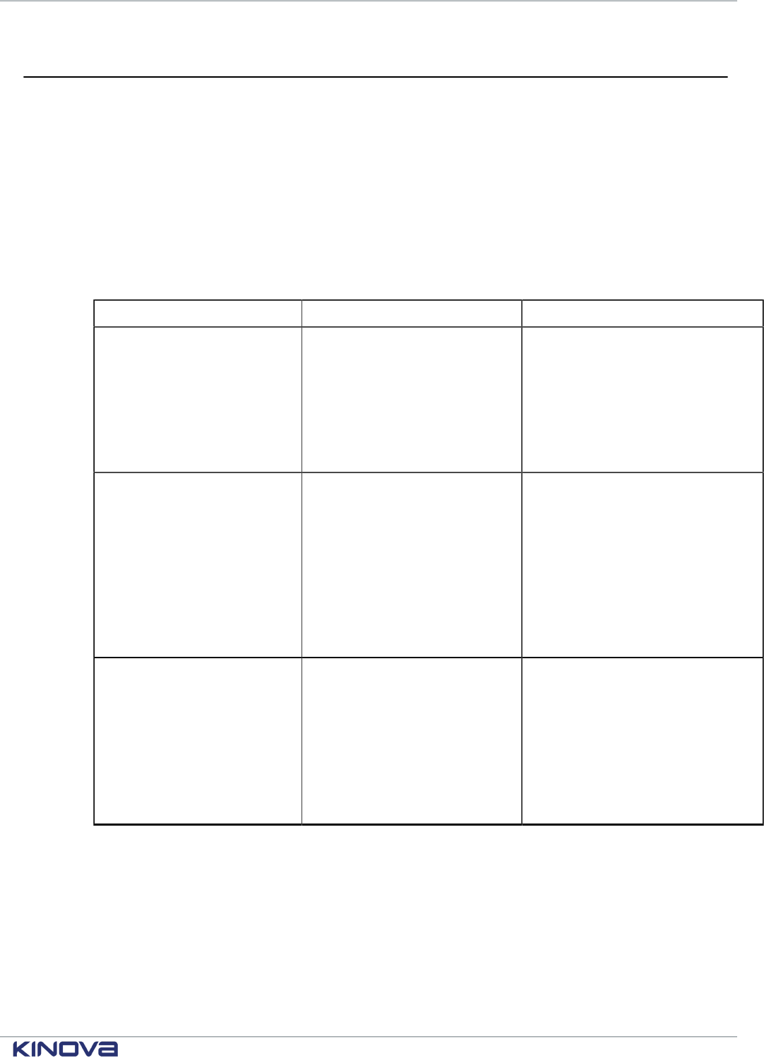
Kinova® Gen3 Ultra lightweight robot User Guide 201
7 DoF singular configurations
Description of the singular configurations of the 7 DoF robot.
Singular configurations overview
Singularities generally occur when a particular angular configuration of the robot causes axes to be
aligned. This causes the robot to lose degrees of freedom and experience limitations in movement
in some directions while operating the robot in Cartesian mode. There are many ways that this
could potentially happen, and an exhaustive listing would be difficult. The following table highlights
some important singular configurations for the 7 DoF robot, explaining how they occur and how the
robot behavior is altered near the singularity while in Cartesian mode.
Table 96: Selected singular configurations description
Singularity Definition Description
Boundary singularity The arm is at full reach. Joint 4
(elbow) is at 0°. The arm cannot
move any farther in the direction
it is currently reaching out.
The robot will slowly try to reach
a straight position. If you try to
move the robot purely in the x or y
direction starting from this position,
you will not be able to. The robot
will follow the command as best as
possible. It will move in x and y while
going down in the z direction.
Joints 2 and 3 singularity Joint 2 is at 0° so joints 1 and 3
are perfectly aligned and have the
same effect.
Joint 3 is at 90° or at 270° so
that the axes of joint 2 and
joint 4 are perpendicular.
The robot can no longer
move purely along an axis in
translation.
Due to singularity crossing algorithm,
the robot will make a minor deviation
from a straight line trajectory when
going through this pose in Cartesian
mode.
Joints 2 and 6 singularity Joint 2 is at 0° so that joints 1 and
3 are perfectly aligned and have
the same effect.
Joint 6 is at 0° so that joints 5
and 7 are perfectly aligned and
have the same effect. The hand
cannot rotate in one direction
anymore.
Due to singularity crossing algorithm,
the robot will make a minor deviation
from a straight line trajectory when
going through this pose in Cartesian
mode.
+1 514-277-3777 kinovarobotics.com
© 2022 Kinova inc. All rights reserved.
Kinova® Gen3 Ultra lightweight robot User Guide 202
Singularity Definition Description
Joints 5 and 6 singularity Joint 6 is at 0° so that joints 5 and
7 are perfectly aligned and have
the same effect.
Joint 5 is at 90° or at 270° so
that the axes of joint 4 and
joint 6’s axis are perpendicular.
The robot can no longer
complete pure rotations
around an axis.
Due to singularity crossing algorithm,
the robot will make a minor deviation
from a straight line trajectory when
going through this pose in Cartesian
mode.
Joints 1 and 7 singularity Joints 2-5 are positionned so
that joints 1 and 7 are perfectly
aligned and have the same effect
(infinite possibilities of joint
combinations).
Due to singularity crossing algorithm,
the robot will make a minor deviation
from a straight line trajectory when
going through this pose in Cartesian
mode.
6 DoF singular configurations
This section describes the singularity configurations of the 6 DoF robot.
Singularity configurations overview
Singularities generally occur when a particular angular configuration of the robot causes axes to be
aligned, causing the robot to lose degrees of freedom and experience limitations in movement in
some directions while operating the robot in Cartesian mode. There are many ways that this could
potentially happen, and an exhaustive listing would be difficult. The following table highlights some
important singularities for the 6 DoF robot, explaining how they occur and how the robot behavior
is altered near the singularity while in Cartesian mode.
Table 97: Selected singular configurations description
Singularity Definition Description
Boundary singularity The robot is at full extension.
The robot will slowly try to reach
a straight position. If you try
tovmove the robot purely in
thevx or y direction starting
from this position, you will not be
able to. The robot will follow the
command as best as possible. It
will move in x and y while going
down in the z direction.
Joints 1 and 4 singularity Joints 2 and 3 are at 0° so that
joints 1 and 4 are aligned.
Due to singularity crossing algorithm,
the robot will make a minor deviation
from a straight line trajectory when
giong through this pose in Cartesian
mode.
+1 514-277-3777 kinovarobotics.com
© 2022 Kinova inc. All rights reserved.
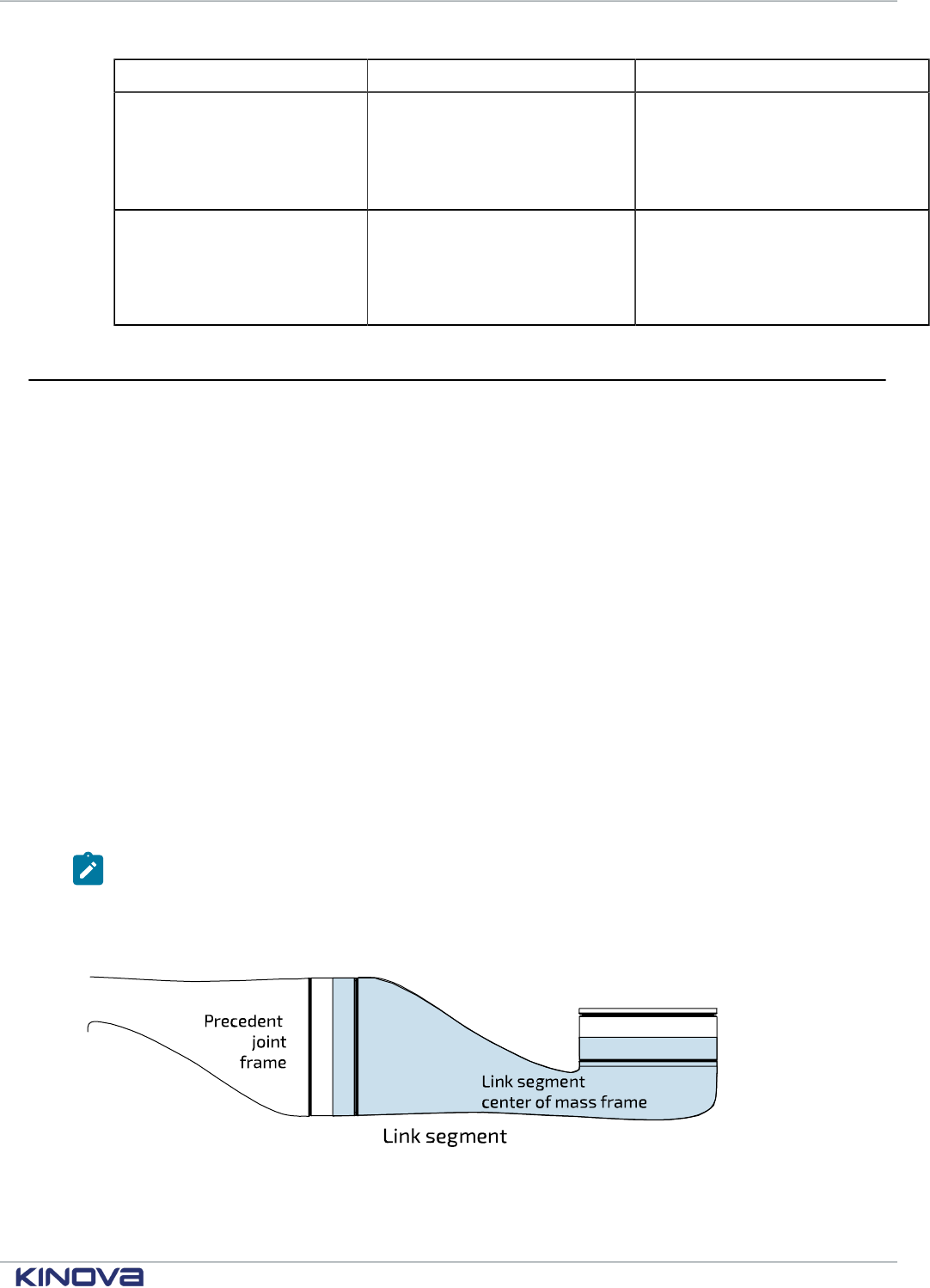
Kinova® Gen3 Ultra lightweight robot User Guide 203
Singularity Definition Description
Joints 1 and 6 singularity Joints 2, 3, and 5 are at a position
such that Joints 1 and 6 are
aligned and have the same effect.
Happens if θ
2
+ θ
3
+ θ
5
= 0 if θ is
defined between ± π.
Due to singularity crossing algorithm,
the robot will make a minor deviation
from a straight line trajectory when
going thorugh this pose in Cartesian
mode.
Joints 4 and 6 singularity Joint 5 is at 0° so joints 4 and 6
are perfectly aligned and have the
same effect.
Due to singularity crossing algorithm,
the robot wil make a minor deviation
from a straight line trajectory when
going through this pose in Cartesian
mode.
Inertial parameters definition
Inertial parameters are provided for the robot.
Overview
The following tables describe the key inertial parameters of each independently moving rigid link
segment of the 7 robot. This includes:
• mass in kg
• centers of masses in meters
•
moments of inertia in kg * m
2
The six distinct moments of inertia (Ixx, Ixy, Ixz, Iyy, Iyz, Izz) are presented in tabular form.
Conventions used
The following conventions are used:
1. The center of mass of a link is always expressed in terms of the reference frame of the precedent
joint.
2. The mass of a link segment includes the shell and portions of the actuators at each end of the
link (as applicable) that are enclosed within the link and move rigidly with the link.
3. The moments of inertia of the link segments are taken in a frame defined at the center of mass of
the link segment and aligned with the precedent joint frame.
Note: These conventions align with those used in URDF files in the <inertial> section of
<link> definitions.
Figure 90: Inertial parameters conventions
+1 514-277-3777 kinovarobotics.com
© 2022 Kinova inc. All rights reserved.
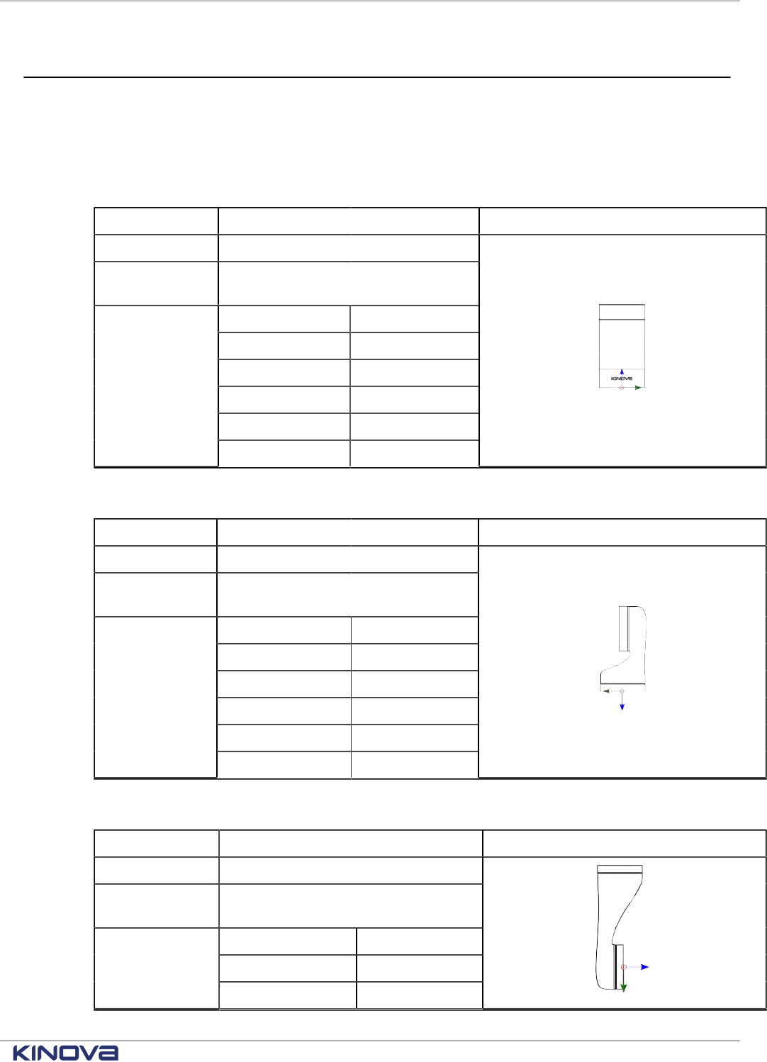
Kinova® Gen3 Ultra lightweight robot User Guide 204
Inertial parameters of the 7 DoF robot
Inertial parameters of the 7 DoF robot.
Overview
The following tables describe the key inertial parameters of the link segments of the 7 DoF robot.
Table 98: Base
Physical quantity Value
mass (kg) 1.697
center of mass
coordinates (m)
[-0.000648, -0.000166, 0.084487]
Ixx 0.004622
Ixy 0.000009
Ixz 0.000060
Iyy 0.004495
Iyz 0.000009
moments of
inertia (kg · m
2
)
Izz 0.002079
Table 99: Link 1
Physical quantity Value
mass (kg) 1.377
center of mass
coordinates (m)
[-0.000023, -0.010364, -0.073360]
Ixx 0.004570
Ixy 0.000001
Ixz 0.000002
Iyy 0.004831
Iyz 0.000448
moments of
inertia (kg · m
2
)
Izz 0.001409
Table 100: Link 2
Physical quantity Value
mass (kg) 1.1636
center of mass
coordinates (m)
[-0.000044, -0.099580, -0.013278]
Ixx 0.011088
Ixy 0.000005
moments of
inertia (kg · m
2
)
Ixz 0.000000
+1 514-277-3777 kinovarobotics.com
© 2022 Kinova inc. All rights reserved.
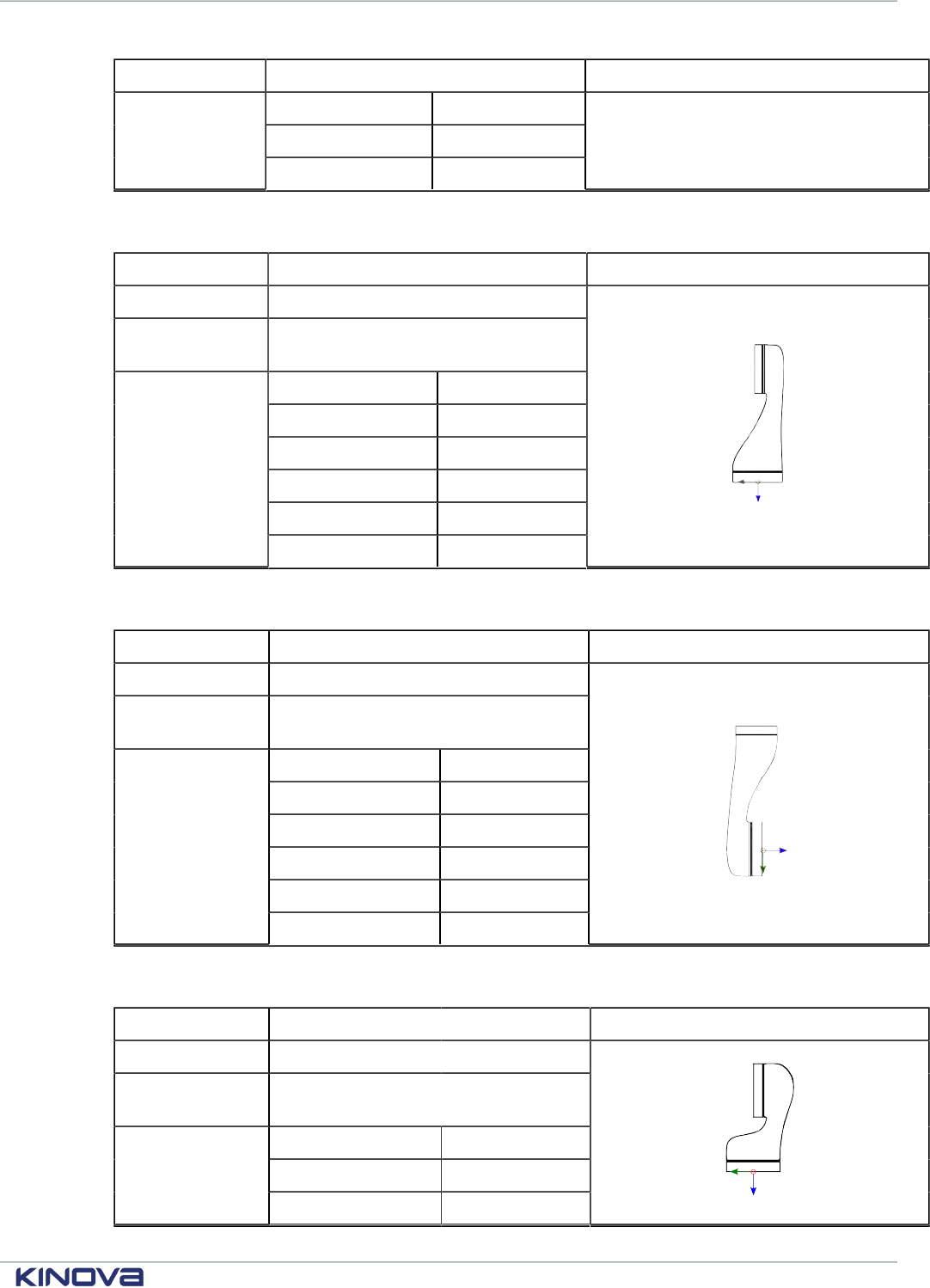
Kinova® Gen3 Ultra lightweight robot User Guide 205
Physical quantity Value
Iyy 0.001072
Iyz -0.000691
Izz 0.011255
Table 101: Link 3
Physical quantity Value
mass (kg) 1.1636
center of mass
coordinates (m)
[-0.000044, -0.006641, -0.117892]
Ixx 0.010932
Ixy 0.000000
Ixz -0.000007
Iyy 0.011127
Iyz 0.000606
moments of
inertia (kg · m
2
)
Izz 0.001043
Table 102: Link 4
Physical quantity Value
mass (kg) 0.930
center of mass
coordinates (m)
[-0.000018, -0.075478, -0.015006]
Ixx 0.008147
Ixy -0.000001
Ixz 0.000000
Iyy 0.000631
Iyz -0.000500
moments of
inertia (kg · m
2
)
Izz 0.008316
Table 103: Link 5
Physical quantity Value
mass (kg) 0.678
center of mass
coordinates (m)
[0.000001, -0.009432, -0.063883]
Ixx 0.001596
Ixy 0.000000
moments of
inertia (kg · m
2
)
Ixz 0.000000
+1 514-277-3777 kinovarobotics.com
© 2022 Kinova inc. All rights reserved.
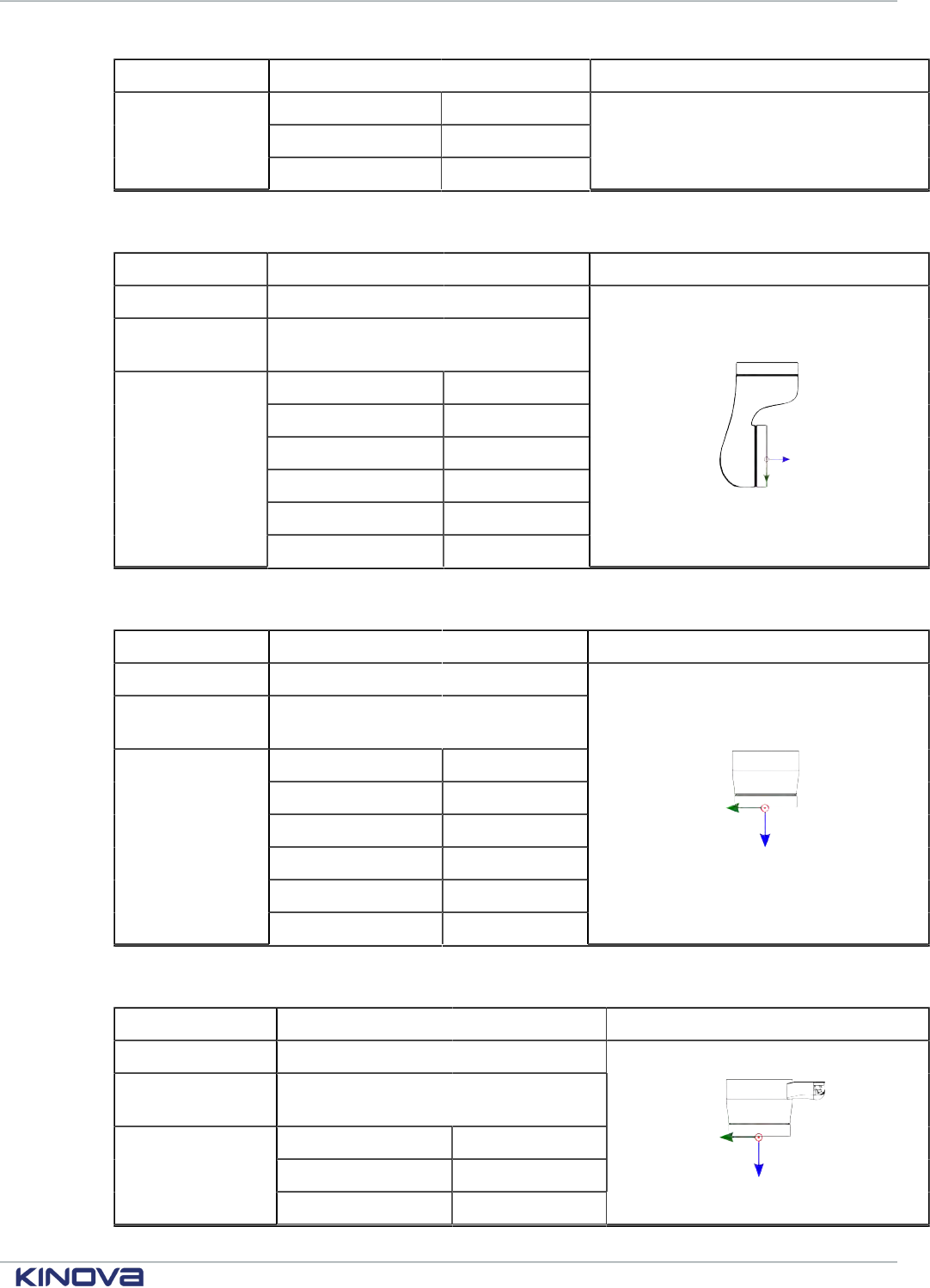
Kinova® Gen3 Ultra lightweight robot User Guide 206
Physical quantity Value
Iyy 0.001607
Iyz 0.000256
Izz 0.000399
Table 104: Link 6
Physical quantity Value
mass (kg) 0.678
center of mass
coordinates (m)
[0.000001, -0.045483, -0.009650]
Ixx 0.001641
Ixy 0.000000
Ixz 0.000000
Iyy 0.000410
Iyz -0.000278
moments of
inertia (kg · m
2
)
Izz 0.001641
Table 105: Interface module without vision module
Physical quantity Value
mass (kg) 0.364
center of mass
coordinates (m)
[-0.000093, 0.000132, -0.022905]
Ixx 0.000214
Ixy 0.000000
Ixz 0.000001
Iyy 0.000223
Iyz -0.000002
moments of
inertia (kg · m
2
)
Izz 0.000240
Table 106: Interface module with vision module
Physical quantity Value
mass (kg) 0.500
center of mass
coordinates (m)
[-0.000281, -0.011402, -0.029798]
Ixx 0.000587
Ixy 0.000003
moments of
inertia (kg · m
2
)
Ixz 0.000003
+1 514-277-3777 kinovarobotics.com
© 2022 Kinova inc. All rights reserved.
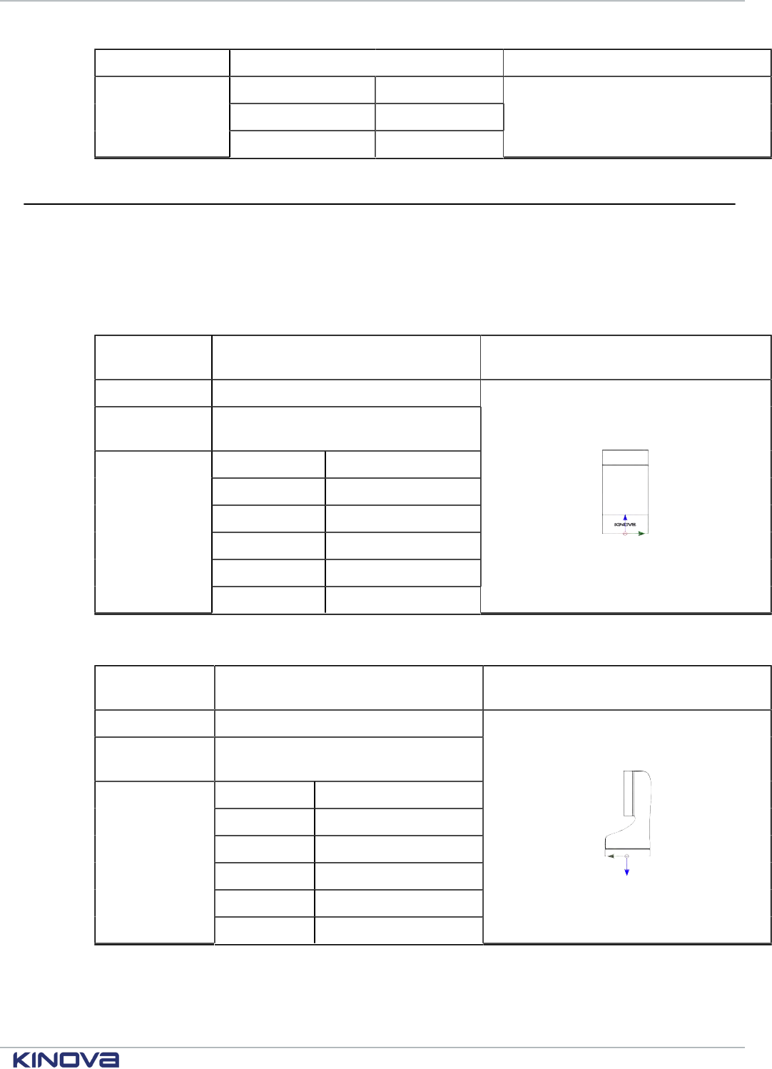
Kinova® Gen3 Ultra lightweight robot User Guide 207
Physical quantity Value
Iyy 0.000369
Iyz 0.000118
Izz 0.000609
Inertial parameters of the 6 DoF robot
Inertial parameters of the 6 DoF robot.
Overview
The following tables describe the key inertial parameters of the link segments of the 6 DoF robot.
Table 107: Base
Physical
quantity
Value Image
mass (kg) 1.697
center of mass
coordinates (m)
[-0.000648, -0.000166, 0.084487]
Ixx 0.004622
Ixy 0.000009
Ixz 0.000060
Iyy 0.004495
Iyz 0.000009
moments of
inertia (kg · m
2
)
Izz 0.002079
Table 108: Link 1
Physical
quantity
Value Image
mass (kg) 1.377
center of mass
coordinates (m)
[-0.000023, -0.010364, -0.073360]
Ixx 0.004570
Ixy 0.000001
Ixz 0.000002
Iyy 0.004831
Iyz 0.000448
moments of
inertia (kg · m
2
)
Izz 0.001409
+1 514-277-3777 kinovarobotics.com
© 2022 Kinova inc. All rights reserved.
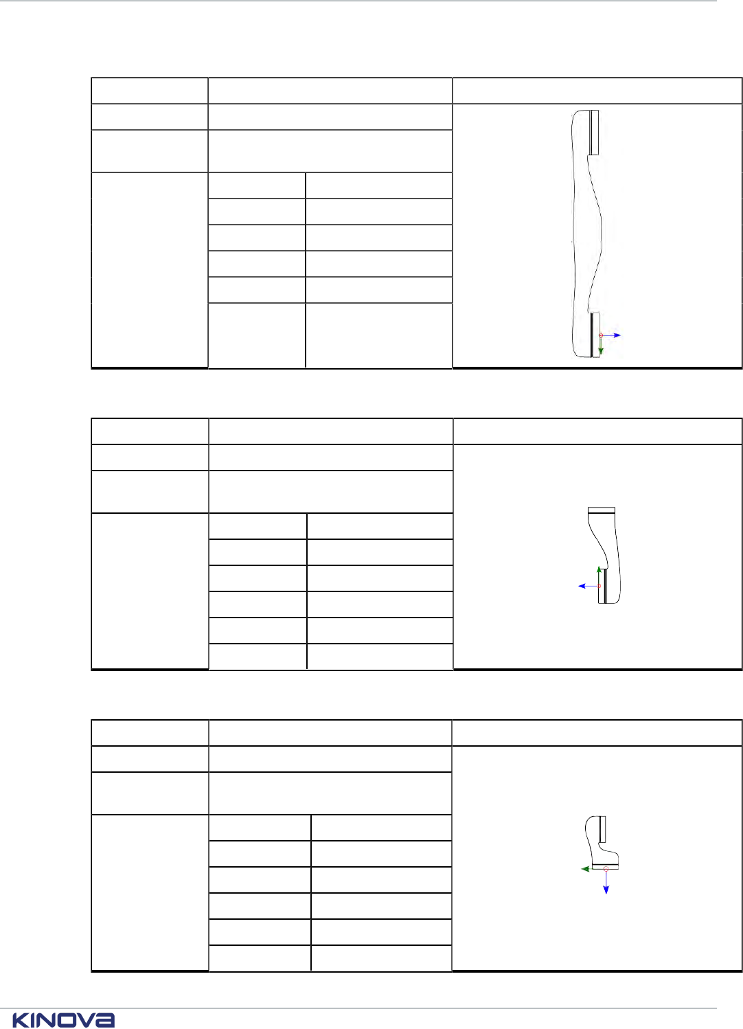
Kinova® Gen3 Ultra lightweight robot User Guide 208
Table 109: Link 2
Physical quantity Value Image
mass (kg) 1.262 kg
center of mass
coordinates (m)
[0.000035, -0.208207, -0.018890]
Ixx 0.046752
Ixy -0.000009
Ixz 0.000000
Iyy 0.000850
Iyz -0.000098
moments of
inertia (kg · m
2
)
Izz 0.047188
Table 110: Link 3
Physical quantity Value Image
mass (kg) 0.930
center of mass
coordinates (m)
[0.000018, 0.076168, -0.013970]
Ixx 0.008292
Ixy -0.000001
Ixz 0.000000
Iyy 0.000628
Iyz 0.000432
moments of
inertia (kg · m
2
)
Izz 0.008464
Table 111: Link 4
Physical quantity Value Image
mass (kg) 0.678
center of mass
coordinates (m)
[-0.000001, 0.008466, -0.062937]
Ixx 0.001645
Ixy 0.000000
Ixz 0.000000
Iyy 0.001666
Iyz -0.000234
moments of
inertia (kg · m
2
)
Izz 0.000389
+1 514-277-3777 kinovarobotics.com
© 2022 Kinova inc. All rights reserved.
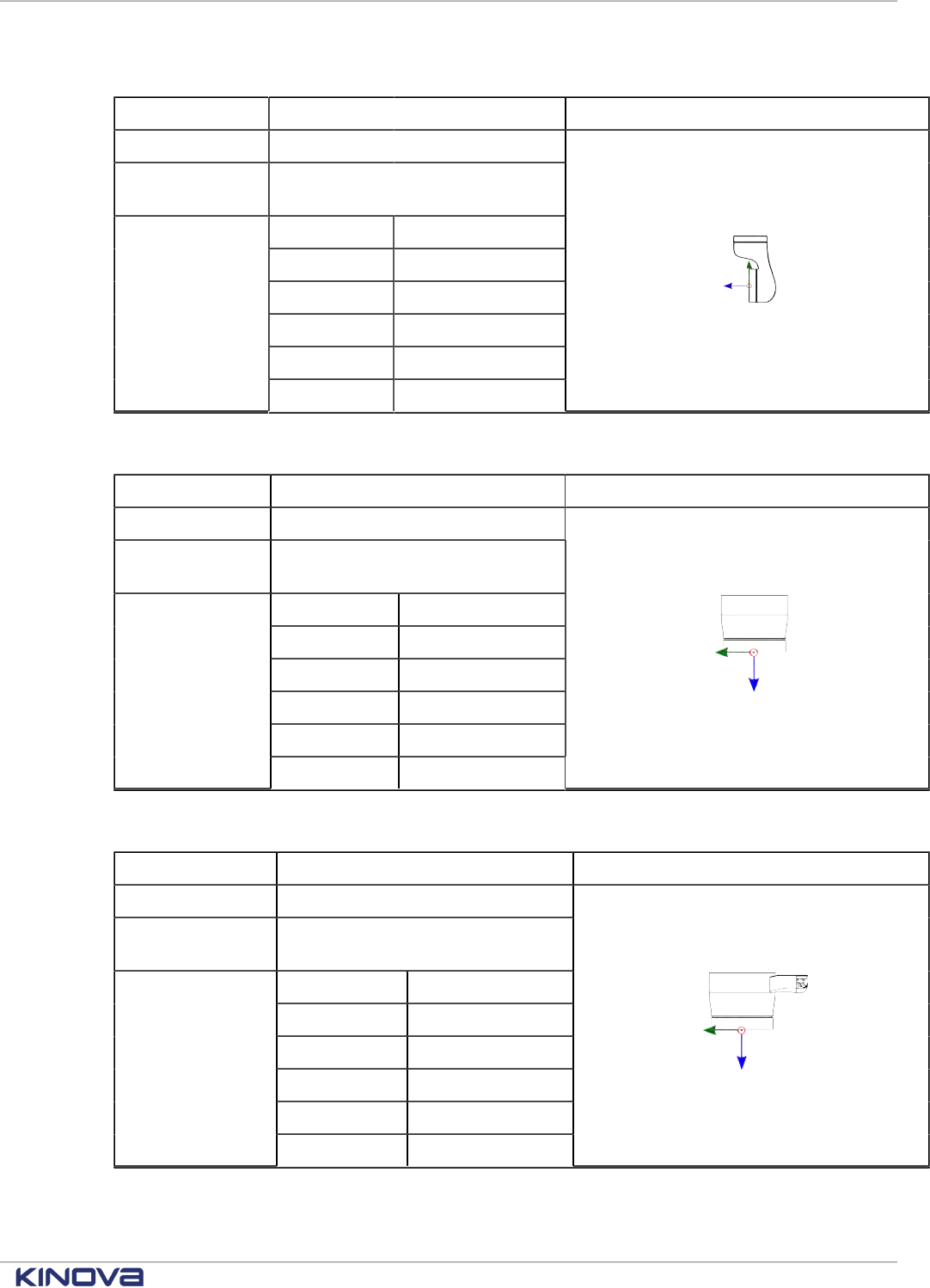
Kinova® Gen3 Ultra lightweight robot User Guide 209
Table 112: Link 5
Physical quantity Value Image
mass (kg) 0.678
center of mass
coordinates (m)
[-0.000001, 0.046429, -0.008704]
Ixx 0.001685
Ixy 0.000000
Ixz 0.000000
Iyy 0.000400
Iyz 0.000255
moments of
inertia (kg · m
2
)
Izz 0.001696
Table 113: Interface module without vision module
Physical quantity Value
mass (kg) 0.364
center of mass
coordinates (m)
[-0.000093, 0.000132, -0.022905]
Ixx 0.000214
Ixy 0.000000
Ixz 0.000001
Iyy 0.000223
Iyz -0.000002
moments of
inertia (kg · m
2
)
Izz 0.000240
Table 114: Interface module with vision module
Physical quantity Value Image
mass (kg) 0.500
center of mass
coordinates (m)
[0.000281, 0.011402, -0.029798]
Ixx 0.000587
Ixy 0.000003
Ixz 0.000003
Iyy 0.000369
Iyz -0.000118
moments of
inertia (kg · m
2
)
Izz 0.000609
+1 514-277-3777 kinovarobotics.com
© 2022 Kinova inc. All rights reserved.
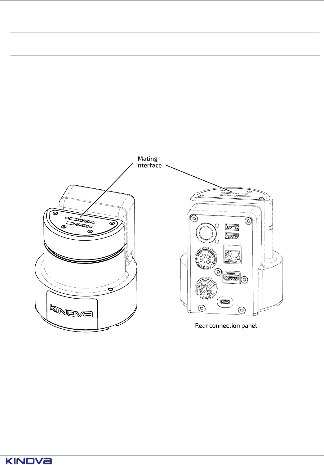
Kinova® Gen3 Ultra lightweight robot User Guide 210
Maintenance and troubleshooting
Maintenance
Overview of maintenance tasks for the robot.
Maintenance overview
Currently, none of the components of the robot are field replaceable. Contact Kinova for assistance
in the case of any component breakdown or malfunction.
Preventive Maintenance
Some preventive maintenance tasks are helpful for protecting your robot and getting the most out
it over time:
• Cleaning contacts on base controller - keep contacts clear of dust and contamination, wiping
electrical contacts regularly with a soft moistened cloth.
+1 514-277-3777 kinovarobotics.com
© 2022 Kinova inc. All rights reserved.
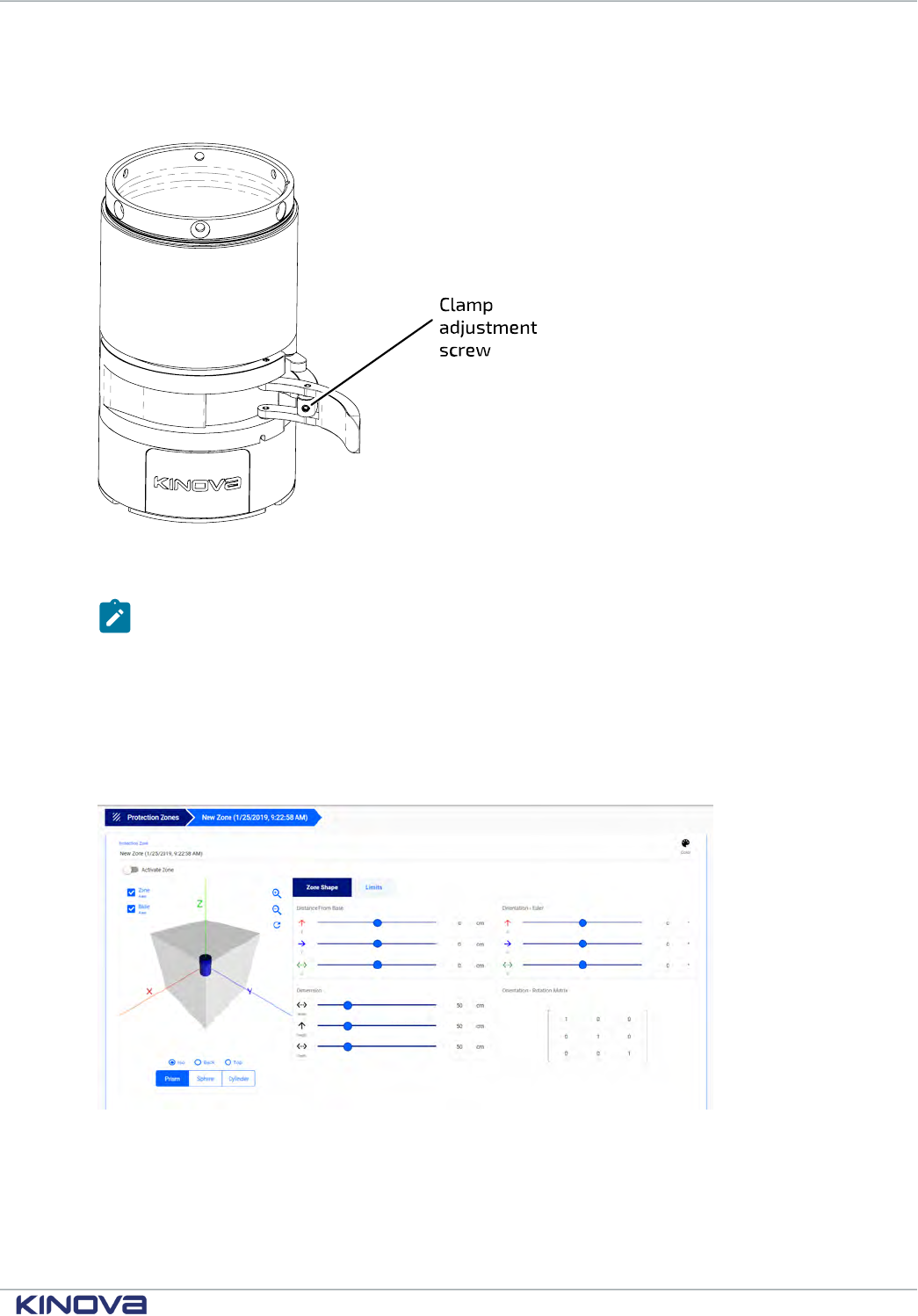
Kinova® Gen3 Ultra lightweight robot User Guide 211
• Fine adjustment of base clamp - Some adjustment may be needed for the base clamp to ensure
that the robot is firmly clamped onto the base controller. Within the clamp is an adjustment
screw which can be adjusted to tighten the clamp as needed.
To tighten the clamp turn the screw clockwise using a 2 mm hex key in small, ¼ turn increments,
testing the clamp after each increment.
Note: Overtightening the clamp can damage the clamp and base. Always make sure that
the clamp can be closed using a reasonable amount of force.
• Cleaning glass on vision module - the cameras on the vision module are covered in glass. For
best results, keep the glass clear of contamination that could block the view of the sensors. Wipe
the glass regularly with a soft moistened cloth and wipe dry with a soft dry cloth.
• Setting protection zones - volumetric protection zones should be established around the robot
to protect it from potential damage caused by collisions with known obstacles. Protection zones
can be set using the Kinova
®
Kortex™ Web App.
• Updating robot firmware - Kinova will periodically release software upgrade packages to
fix known bugs and expand the capabilities of the robot. For best results, it is recommended
to regularly update robot software using the Web App. The most up to date upgrade
+1 514-277-3777 kinovarobotics.com
© 2022 Kinova inc. All rights reserved.
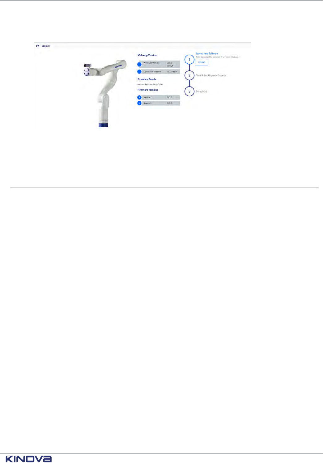
Kinova® Gen3 Ultra lightweight robot User Guide 212
package is available for download via the Kinova website product technical resources page:
kinovarobotics.com/knowledge-hub/gen3-ultra-lightweight-robot
•
Updating development packages - Kinova will periodically release updates for the Kinova
®
Kortex™, Kinova
®
Kortex™ ROS, and Kinova
®
Kortex™ ROS vision packages on the
kinovarobotics/kortex, kinovarobotics/ros_kortex, and kinovarobotics/ros_kortex_vision GitHub
repositories. These updates will fix known bugs and expand the capabilities of the robot.
Troubleshooting
Tips for troubleshooting robot issues.
If the robot loses a part (for example a shell due to impact) or if a part breaks, shut down the robot
safely and leave it off. Contact Kinova technical support.
Troubleshooting resources
There are several resources that can be used to help diagnose issues when they occur:
•
Kinova
®
Kortex™ Web App notifications
• Web App monitoring - the monitoring page provides useful status information on the robot
components, including the base, all actuators, and the interface. Notably, currents, voltages, CPU
core temperatures and motor temperatures from the sensors are updated in real-time on the
monitoring page
• Web App safeties page - when a safety item's warning or error threshold is exceeded, the safety
item will be highlighted in the Robot Configurations Safety page.
• Base controller LED indicators - LEDs on the robot base controller connector panel provide
visual feedback on the robot status
• API errors
• GitHub - information on known issues and workarounds
• release notes
General tips for troubleshooting issues with the robot
When the robot enters a fault state, the robot will become unresponsive until the fault is cleared.
The Xbox gamepad can be used to clear faults - press the left bumper once and proceed.
Consult the Web App:
• Check the Monitoring page for high-level status information on various components.
• Check the Notifications page for any recent notifications.
+1 514-277-3777 kinovarobotics.com
© 2022 Kinova inc. All rights reserved.
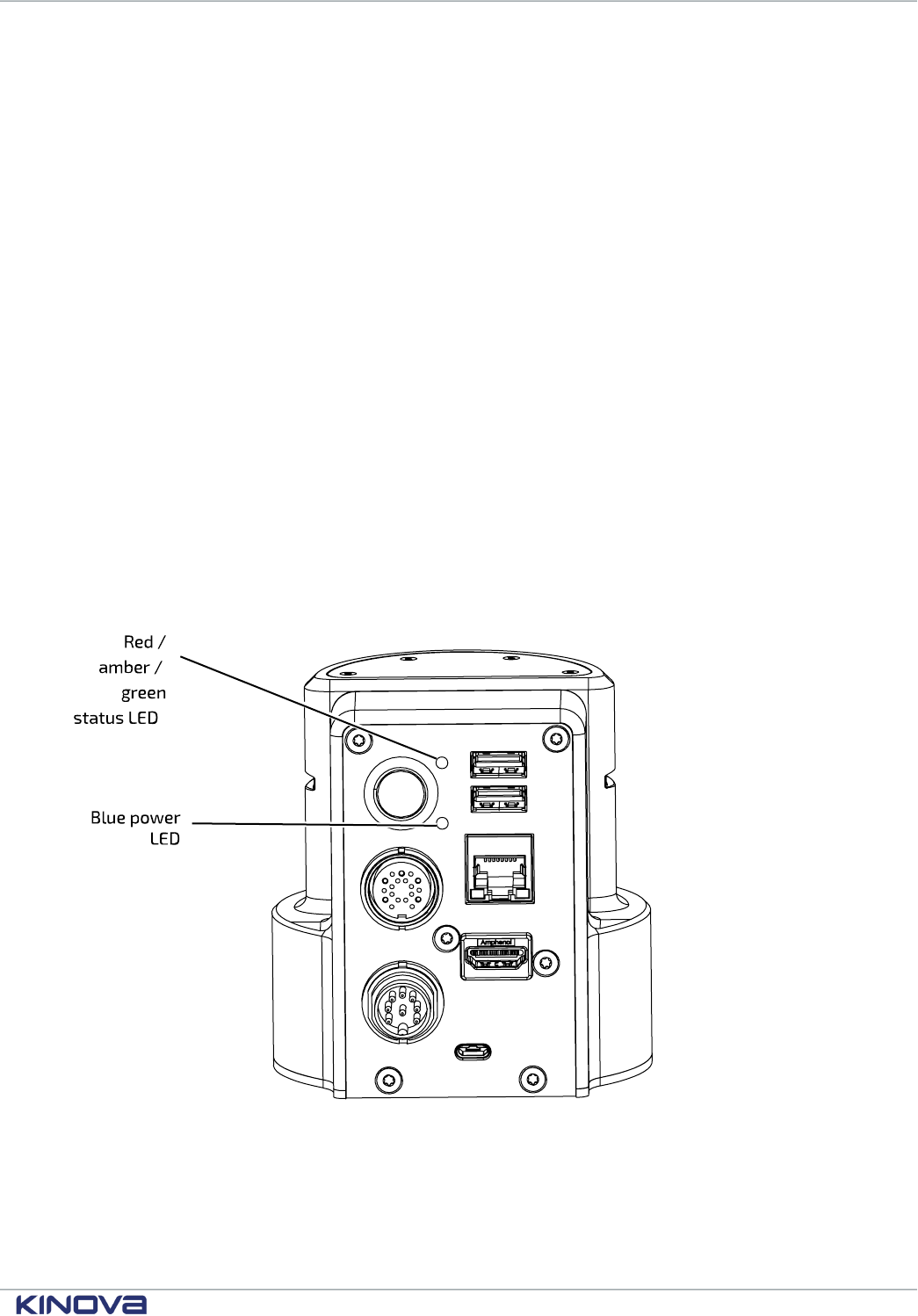
Kinova® Gen3 Ultra lightweight robot User Guide 213
• Check the Safeties page to see if the robot has passed a warning or error threshold. If any safety
us triggered, the safety item will be Look up the information on the safety for guidance on
handling.
Remember that the behavior of the robot will change as the robot nears singularities or enters the
envelope of protection zones. If robot behavior deviates from what you expect, verify whether one
of these two cases applies.
For API-related errors, check the reference tables for guidance on the source of the error and how
to deal with it.
Kinova recommends updating robot firmware and Kinova
®
Kortex™ API packages regularly to keep
up with the latest bug fixes and ensure optimal performance.
As part of periodic software updates, Kinova will publish release notes on the Kinova website.
These notes describe known issues, limitations, and workarounds, as well as information about new
features and previous bugs fixed in the release.
If all else fails, try rebooting the robot.
If you're still experiencing issues, contact Kinova support via the website.
Base LEDs interpretation
Interpretation of the meanings of LED indicators on the robot base.
Overview
The base controller has two LEDs, one blue and one red / green.
Figure 91: Base controller LEDs
Base controller LED details
+1 514-277-3777 kinovarobotics.com
© 2022 Kinova inc. All rights reserved.
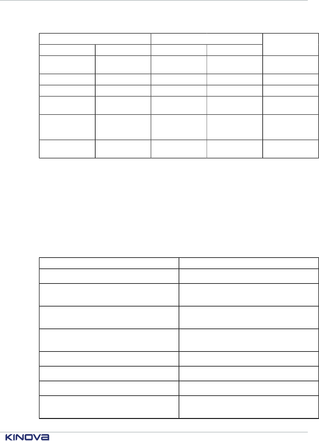
Kinova® Gen3 Ultra lightweight robot User Guide 214
Table 115: LED interpretation
Power LED Status LED
color status color status
Description
n/a off n/a off system not
powered
blue blinking n/a off system booting
blue solid amber solid system initializing
n/a off green solid
system operating
normally
blue blinking amber solid
system currently
updating at least
one component
blue solid red solid system in
error state
How to respond to safety warnings and errors
Guidance on probable causes for safety warnings and error states experiened when operating the robot.
Overview
The robot has a number of warning and error thresholds set for safety purposes. These are
viewable (and in some case configurable) in the Web application. The following tables give more
guidance as to the source of the problem when a safety threshold is triggered.
Safeties handling details
Table 116: Base safeties handling
Safety Most Probable Cause
Incompatible Firmware version • Firmware issue
Firmware Update Failure
• Firmware issue
• Communication issue
Maximum Ambient Temperature
• CPU heat sink issue
• Unknown thermal issue
Maximum Core Temperature
• CPU heat sink issue
• Unknown thermal issue
Joint Fault • Joint error / warning state
Joint Detection Error • Communication issue
Network Initialization Error • Base CPU board issue
Maximum Current
• Shorted phases on a joint
• Payload exceeded
+1 514-277-3777 kinovarobotics.com
© 2022 Kinova inc. All rights reserved.
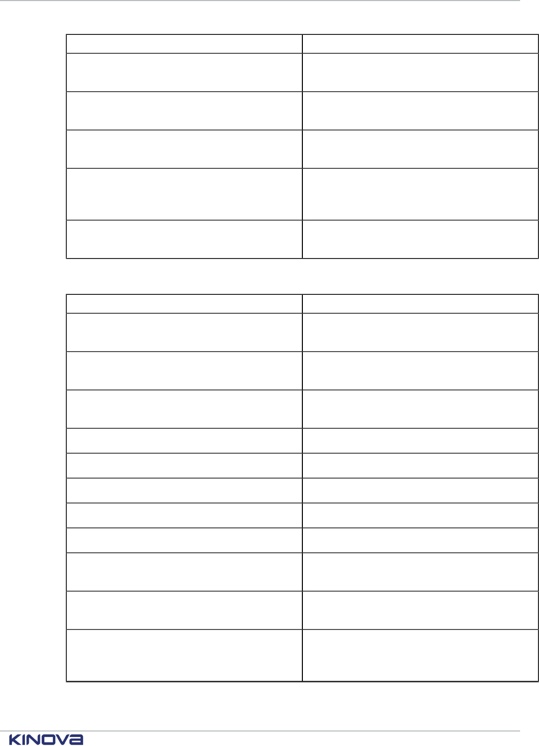
Kinova® Gen3 Ultra lightweight robot User Guide 215
Safety Most Probable Cause
Maximum Voltage
• Power supply issue
• Electronic component failure
Minimum Voltage
• Power supply issue
• Electronic component failure
Emergency Stop Activated
• XBox gamepad emergency stop button clicked
• Web application emergency stop button clicked
Emergency Line Asserted
• Joint not programmed
• Joint in a boot loop
• Electrical component failure
Inrush Current Limiter Fault
• Payload exceeded
• Electrical component failure
Table 117: Actuators safeties handling
Safety Most Probable Cause
Following error
• Communication issue
• Firmware issue
Maximum velocity
• Communication issue
• Firmware issue
Maximum torque
• Strain gauge improperly soldered
• Incorrect torque calibration
Magnetic position • Magnet improperly glued
Hall position • Hall sensor major malfunction
Hall sequence • Hall sensor major malfunction(s)
Input encoder Hall mismatch • Dirt and/or particles on encoder disk
Input encoder index mismatch • Dirt and/or particles on encoder disk
Input encoder magnetic mismatch
• Dirt and/or particles on encoder disk
• Detached magnet on magnetic encoder
Maximum motor current
• Shorted phases
• Bad motor
Non-volatile memory corrupted
• Incomplete calibration(s
• No system information entered
• No torque calibration
+1 514-277-3777 kinovarobotics.com
© 2022 Kinova inc. All rights reserved.
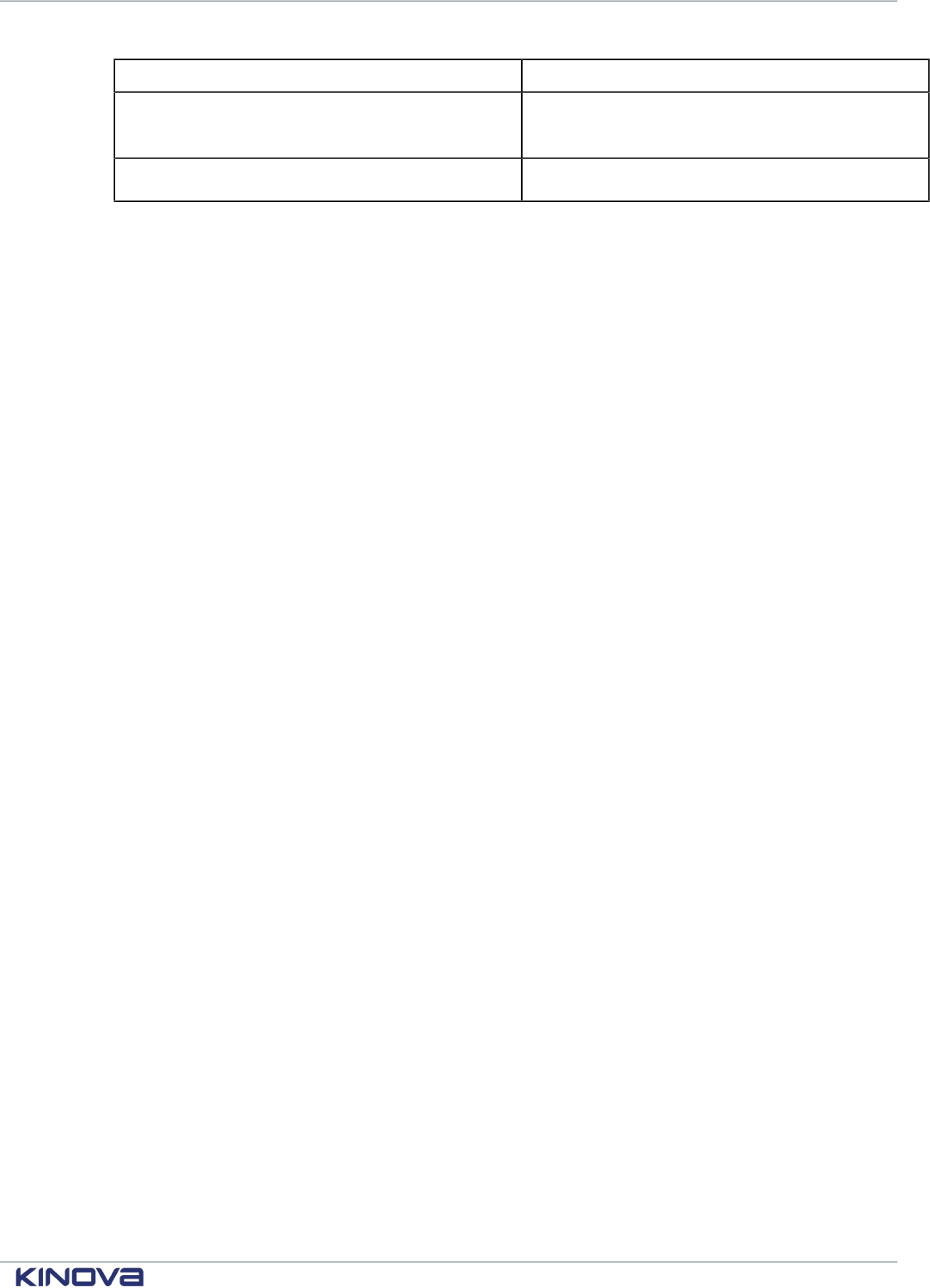
Kinova® Gen3 Ultra lightweight robot User Guide 216
Safety Most Probable Cause
Motor driver fault
• Shorted phases
• Hall sensor issue
Watchdog triggered • Firmware issue
Contacting Kinova support
Here is where to turn for related support and advice.
For support and advice on hardware related issues, please don't hesitate to contact us through the
support form on our website:
www.kinovarobotics.com/support
For development guidance and software-related questions, check out our GitHub repositories:
•
Kinova
®
Kortex™ GitHub: github.com/kinovarobotics/kortex
•
Kinova
®
Kortex™ ROS GitHub: github.com/kinovarobotics/ros_kortex
•
Kinova
®
Kortex™ ROS vision GitHub: github.com/Kinovarobotics/ros_kortex_vision
•
Kinova
®
Kortex™ MATLAB API GitHub: https://github.com/Kinovarobotics/matlab_kortex
+1 514-277-3777 kinovarobotics.com
© 2022 Kinova inc. All rights reserved.
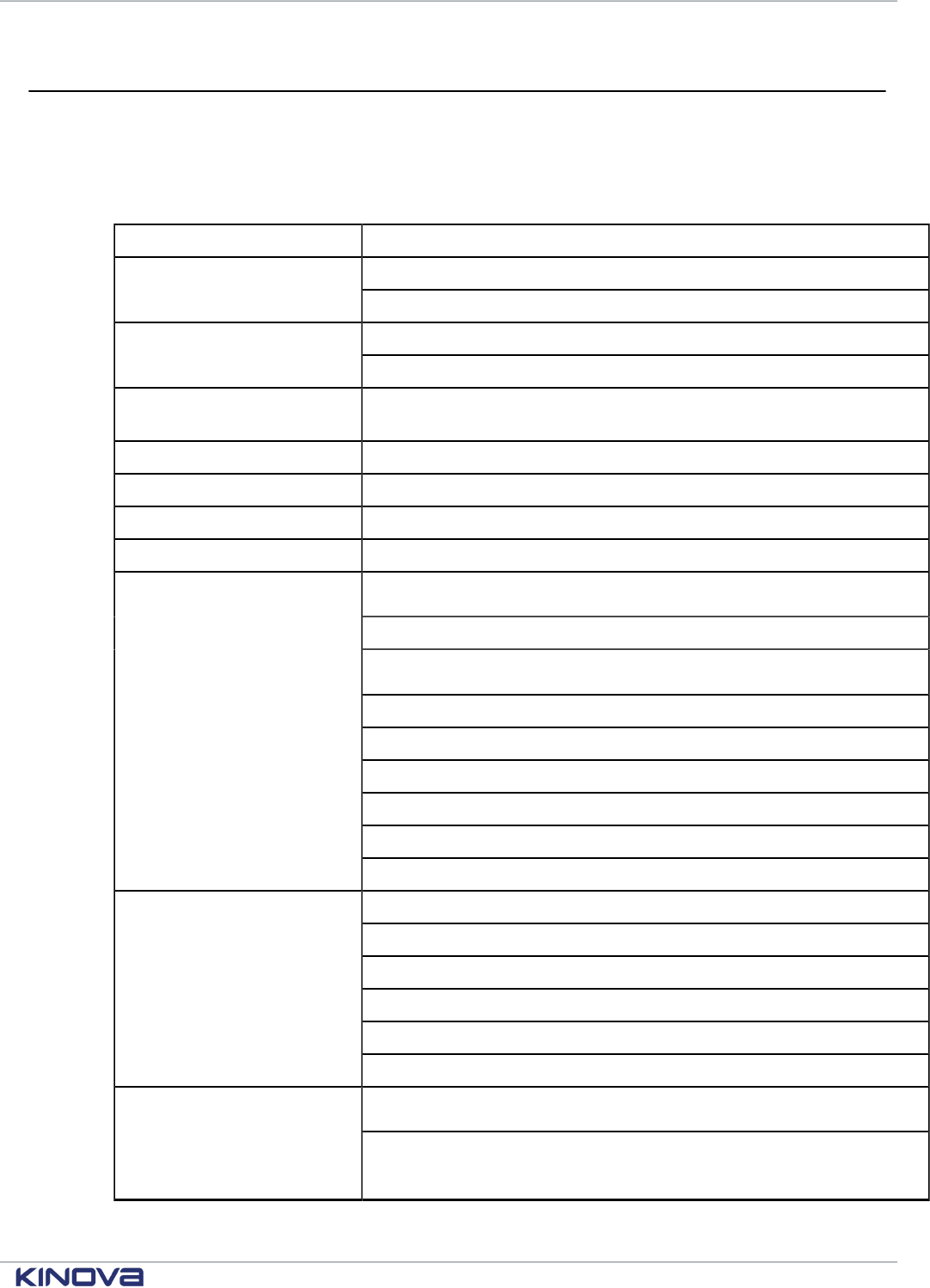
Kinova® Gen3 Ultra lightweight robot User Guide 217
Harmonized Standards, Declarations and Certificates
The following sections provides a list of harmonized standards, declarations and certificates for the Security
arm.
Table 118: Applicable Standards
Item Detail
CISPR 11/24 (equivalent to EN 55011/55024)
EMI / EMC
FCC class B (CFR 47 part 15)
UL94-V0 (shell, PCB)
Flame retardance
UL94-V1 (cables)
Laser
21 CFR 1040.10 (except for deviations in Laser Notice No. 50
2007-06-24)
Universal Serial Bus USB 2.0
Ethernet IEEE 802.3az-2010
Wi-Fi IEEE 802.11a/b/g/n/ac
Bluetooth TBD
ISO 10218-1 Industrial robots
ISO 12100 Safety of machinery
ISO 13849 Safety-related parts of control systems
ISO 14539 Vocabulary only
ISO / TS 15066 Collaborative robots
IEC 60204-1 Safety of machinery – Electrical
IEC 60825-1 Class 1 laser hardware limitation
IEC 60950-1 IT equipment - Safety
ISO / IEC
IEC 61000-6-1/6-3 EMI / EMC
2002/96/EC WEEE
2006/42/EC Machinery directive
2011/65/EU ROHS
2014/30/EU EMC
2014/35/EU LVD
CE
2014/53/EU Radio Equipment directive
OSHA 1910.211 Definitions (To be confirmed)
USA
OSHA 1910.212 General requirements for all machines (To be
confirmed)
+1 514-277-3777 kinovarobotics.com
© 2022 Kinova inc. All rights reserved.
Kinova® Gen3 Ultra lightweight robot User Guide 218
Item Detail
OSHA 1910.214 Cooperage machinery (To be confirmed)
AU AS 2939—1987 Industrial robot systems - Safe design and usage
CA CAN/CSA-Z434-14 Safety
+1 514-277-3777 kinovarobotics.com
© 2022 Kinova inc. All rights reserved.

www.kinovarobotics.com
Kinova inc. (HQ)
4333, boulevard de la Grande-Allée
Boisbriand (QC) J7H 1M7
Canada
+1 (514) 277-3777
Kinova Europe GmbH
Innovation
Großkitzighofer Straße 7 a
86853 Langerringen,
Germany
T.: +49 (0)8248 8887928
Kinova Europe
GmbH
Assistive Technologies
Vorderbreitenthann 150
91555 Feuchtwangen
Germany
T: 0800 5466822
Support: [email protected]
EN-UG-014-r7-202207
