EN50199
EN50192
Plasma Arc
Cutting System
Operator Manual
802900 Rev. 0
®

Plasma Arc Cutting System
Operator Manual
IM-290
(P/N 802900)
Hypertherm, Inc.
P.O. Box 5010
Hanover, New Hampshire 03755-5010
Tel.: 603 643-3441
Fax: 603 643-5352
http://www.hypertherm.com
© Copyright 1997 Hypertherm, Inc.
All Rights Reserved
HYPERTHERM and POWERMAX are trademarks of Hypertherm, Inc. and may be
registered in the United States and/or other countries.
Revision 0 July, 1997
®
Hypertherm Offices Worldwide
:
Hypertherm, Inc.
Etna Road, P.O. Box 5010
Hanover, NH 03755 USA
Tel.: (603) 643-3441 (Main Office)
Fax: (603) 643-5352 (All Departments)
Tel.: (800) 643-9878 (Technical Service)
Tel.: (800) 737-2978 (Customer Service)
Hypertherm Plasmatechnik GmbH
Technologiepark Hanau
Rodenbacher Chaussee 6
D–63457 Hanau-Wolfgang, Germany
Tel.: 49 6181 58 2100
Fax: 49 6181 58 2134
European Technical Support Organization (ETSO)
Technologiepark Hanau
Rodenbacher Chaussee 6
D–63457 Hanau-Wolfgang, Germany
Tel.: 49 6181 58 2100
Fax: 49 6181 58 2134
Hypertherm Singapore Pte Ltd
No. 19 Kaki Bukit Road 2
K.B. Warehouse Complex
Singapore 417847, Republic of Singapore
Tel.: 65 841 2489
Fax: 65 841 2490
Hypertherm U.K.
9 Berkeley Court • Manor Park
Runcorn, Cheshire, England WA7 1TQ
Tel.: 44 1928 579 074
Fax: 44 1928 579 604
Hypertherm France
10, Allée de I’lsara
F-95000 Cergy-Pontoise, France
Tel.: 33 1 34 24 03 05
Fax: 33 1 34 25 09 64
Hypertherm Italy
Via Torino 2
20123 Milan, Italy
Tel.: 39 02 725 46 312
Fax: 39 02 725 46 400

i
Operator Manual
E
LECTROMAGNETIC
C
OMPATIBILITY
EMC INTRODUCTION
The 115/230V CE power supply has been
built in compliance with standard
EN50199. To ensure that the equipment
works in a compatible manner with other
radio and electronic systems, the
equipment should be installed and used in
accordance with the information below to
achieve electromagnetic compatibility.
The limits required by EN50199 may not
be adequate to completely eliminate
interference when the affected equipment
is in close proximity or has a high degree
of sensitivity. In such cases it may be
necessary to use other measures to
further reduce interference.
This plasma equipment should be used
only in an industrial environment. It may
be difficult to ensure electromagnetic
compatibility in a domestic environment.
INSTALLATION AND USE
The user is responsible for installing and
using the plasma equipment according to
the manufacturer's instructions. If
electromagnetic disturbances are
detected then it shall be the responsibility
of the user to resolve the situation with the
technical assistance of the manufacturer.
In some cases this remedial action may be
as simple as earthing the cutting circuit,
see
Earthing of Workpiece
. In other cases
it could involve constructing an
electromagnetic screen enclosing the
power source and the work complete with
associated input filters. In all cases
electromagnetic disturbances must be
reduced to the point where they are no
longer troublesome.
ASSESSMENT OF AREA
Before installing the equipment the user
shall make an assessment of potential
electromagnetic problems in the
surrounding area. The following shall be
taken into account:
a. Other supply cables, control cables,
signalling and telephone cables; above,
below and adjacent to the cutting
equipment.
b. Radio and television transmitters and
receivers.
c. Computer and other control equipment.
d. Safety critical equipment, for example
guarding of industrial equipment.
e. Health of the people around, for
example the use of pacemakers and
hearing aids.
f. Equipment used for calibration or
measurement.
g. Immunity of other equipment in the
environment. User shall ensure that
other equipment being used in the
environment is compatible. This may
require additional protection measures.
h. Time of day that cutting or other
activities are to be carried out.
The size of the surrounding area to be
considered will depend on the structure of
the building and other activities that are
taking place. The surrounding area may
extend beyond the boundaries of the
premises.
METHODS OF REDUCING
EMISSIONS
Mains Supply
Cutting equipment should be connected
to the mains supply according to the
manufacturer's recommendations. If
interference occurs, it may be necessary
to take additional precautions such as
filtering of the mains supply.
Consideration should be given to
shielding the supply cable of permanently
installed cutting equipment, in metallic
conduit or equivalent. Shielding should
be electrically continuous throughout its
length. The shielding should be
connected to the cutting mains supply so
that good electrical contact is maintained
between the conduit and the cutting
power source enclosure.
Maintenance of Cutting Equipment
The cutting equipment should be
routinely maintained according to the
manufacturer's recommendations. All
access and service doors and covers
should be closed and properly fastened
when the cutting equipment is in
operation. The cutting equipment should
not be modified in any way except for
those changes and adjustments covered
in the manufacturer's instructions. In
particular, the spark gaps of arc striking
and stabilizing devices should be
adjusted and maintained according to the
manufacturer's recommendations.
Cutting Cables
The cutting cables should be kept as
short as possible and should be
positioned close together, running at or
close to the floor level.
Equipotential Bonding
Bonding of all metallic components in the
cutting installation and adjacent to it
should be considered. However, metallic
components bonded to the workpiece will
increase the risk that the operator could
receive a shock by touching these
metallic components and the electrode at
the same time. The operator should be
insulated from all such bonded metallic
components.
Earthing of Workpiece
Where the workpiece is not bonded to
earth for electrical safety, nor connected
to earth because of its size and position,
for example, ship's hull or building
steelwork, a connection bonding the
workpiece to earth may reduce
emissions in some, but not all instances.
Care should be taken to prevent the
earthing of the workpiece increasing the
risk of injury to users, or damage to other
electrical equipment. Where necessary,
the connection of the workpiece to earth
should be made by a direct connection to
the workpiece, but in some countries
where direct connection is not permitted,
the bonding should be achieved by
suitable capacitances selected
according to national regulations.
Note: The cutting circuit may or may not
be earthed for safety reasons. Changing
the earthing arrangements should only
be authorized by a person who is
competent to assess whether the
changes will increase the risk of injury, for
example, by allowing parallel cutting
current return paths which may damage
the earth circuits of other equipment.
Further guidance is given in IEC TC26
(sec)94 and IEC TC26/108A/CD Arc
Welding Equipment Installation and Use.
Screening and Shielding
Selective screening and shielding of
other cables and equipment in the
surrounding area may alleviate problems
of interference. Screening of the entire
plasma cutting installation may be
considered for special applications.

ii
Operator Manual
W
ARRANTY
GENERAL
HYPERTHERM, Inc. warrants that Products shall be free from defects in materials and workmanship,
under proper and normal use for which such Equipment is recommended, for a period of two (2) years,
except only with respect to the Torch, for which the warranty period shall be one (1) year, from the date
of its delivery to you.
HYPERTHERM, at its sole option, shall repair, replace, or adjust, free of charge, any Products covered
by this warranty which shall be returned with HYPERTHERM's prior authorization (which shall not be
unreasonably withheld), properly packed, to HYPERTHERM's place of business in Hanover, New
Hampshire, all costs, insurance and freight prepaid, and which examination proves not to be free from
defects in materials and workmanship. HYPERTHERM shall not be liable for any repairs, replace-
ments, or adjustments of Products covered by this warranty, except those made pursuant to this para-
graph or with HYPERTHERM's written consent. This warranty shall not apply to any Product which has
been mishandled, incorrectly installed, modified or assembled by you or any other person. HYPER-
THERM shall be liable for breach of this warranty only if it receives written notice of such breach within
the applicable warranty period specified herein above. THE FOREGOING SHALL CONSTITUTE THE
SOLE REMEDY TO DISTRIBUTORS OR THEIR CUSTOMERS FOR ANY BREACH BY HYPER-
THERM OF ITS WARRANTY.
PATENT INDEMNITY
Except only in cases of Products not manufactured by HYPERTHERM or manufactured by a person
other than HYPERTHERM not in strict conformity with HYPERTHERM's specifications, and in cases of
designs, processes, formulae or combinations not developed or purported to be developed by HYPER-
THERM, HYPERTHERM agrees to indemnify, protect and hold harmless Distributors and their custom-
ers against any and all liability or claims in any manner imposed upon or accruing against Distributors
and their customers because of the use in or about the construction or operation of Equipment or any
design, system, formula, combination, article or material which infringes or alleges to infringe on any
patent or other right. Distributors shall notify HYPERTHERM promptly upon learning of any action or
threatened action in connection with any such alleged infringement, and each party may appoint its own
counsel for any such action or threatened action.
DISCLAIMER OF OTHER WARRANTIES
HYPERTHERM MAKES NO WARRANTIES REGARDING PRODUCTS MANUFACTURED BY IT OR
OTHERS (INCLUDING WITHOUT IMPLIED LIMITATION WARRANTIES AS TO MERCHANTABILITY
OR FITNESS FOR A PARTICULAR PURPOSE), EITHER EXPRESS OR IMPLIED, EXCEPT AS
PROVIDED HEREIN. This warranty is in lieu of any and all warranties, express or implied, by law or
otherwise; and Distributors are not authorized to give any other warranty purporting to be binding upon
HYPERTHERM upon resale of Products to their customers. IN NO EVENT shall HYPERTHERM be
liable for incidental or consequential damages or injury to the person or property of anyone by reason of
any defect in any Equipment sold hereunder.
WARNING
Genuine Hypertherm parts are the factory-recommended replacement parts for your
Hypertherm system. Any damage caused by the use of other than genuine
Hypertherm parts may not be covered by the Hypertherm warranty.

TABLE OF CONTENTS
Operator Manual
ELECTROMAGNETIC COMPATIBILITY .............................................................................................. i
WARRANTY ..........................................................................................................................................ii
SECTION 1 SAFETY .................................................................................................................... 1-1
About Notes, Cautions & Warnings .................................................................................................... 1-1
Safety Instructions.............................................................................................................................. 1-2
Eye Protection .............................................................................................................................. 1-2
Skin Protection ............................................................................................................................. 1-2
Toxic Fume Protection.................................................................................................................. 1-2
Fire Prevention ............................................................................................................................. 1-2
Electric Shock Prevention ............................................................................................................ 1-2
Explosion Prevention ................................................................................................................... 1-3
Noise Protection ........................................................................................................................... 1-4
Grounding .................................................................................................................................... 1-4
Safety Reminders......................................................................................................................... 1-4
Electronic Health Support Equipment .......................................................................................... 1-4
SECTION 1A SÉCURITÉ ............................................................................................................. 1a-1
Au sujet des Notes, Attention et avertissement................................................................................ 1a-1
Consignes de sécurité...................................................................................................................... 1a-2
Protection des yeux.................................................................................................................... 1a-2
Protection de la peau ................................................................................................................. 1a-2
Prévention des vapeurs toxiques ............................................................................................... 1a-2
Prévention des incendies ........................................................................................................... 1a-2
Prévention des chocs électriques .............................................................................................. 1a-2
Prévention des explosions ......................................................................................................... 1a-3
Protection contre le bruit ............................................................................................................ 1a-4
Mise à la masse et à la terre ...................................................................................................... 1a-4
Rappels de sécurité ................................................................................................................... 1a-4
Prothèses électroniques............................................................................................................. 1a-4
SECTION 2 SPECIFICATIONS ...................................................................................................... 2-1
Introduction ........................................................................................................................................ 2-2
Specifications ..................................................................................................................................... 2-2
Power Supply ............................................................................................................................... 2-2
PAC110 Torch.............................................................................................................................. 2-3
S Mark ............................................................................................................................................. 2-4
IEC Symbols Used ............................................................................................................................. 2-4
SECTION 3 SETUP........................................................................................................................ 3-1
Upon Receipt ..................................................................................................................................... 3-2
Claims ................................................................................................................................................ 3-2
Locating Power Supply ...................................................................................................................... 3-2
115/215 Voltage Configurations ......................................................................................................... 3-2
Input Voltage Selector Switch ...................................................................................................... 3-2
Power Cord Plugs ........................................................................................................................ 3-2
Grounding .......................................................................................................................................... 3-4
Work Cable and Clamp ...................................................................................................................... 3-4
Plasma Air Supply .............................................................................................................................. 3-4
iii

TABLE OF CONTENTS
Operator Manual
iv
Additional Air Filtration ................................................................................................................. 3-5
Air Hose Connection .......................................................................................................................... 3-5
SECTION 4 OPERATION ............................................................................................................. 4-1
Controls and Indicators ...................................................................................................................... 4-2
Operating Instructions ........................................................................................................................ 4-3
Operating Tips.................................................................................................................................... 4-4
Changing Consumable Parts ....................................................................................................... 4-4
Cutting .......................................................................................................................................... 4-5
Piercing ........................................................................................................................................ 4-6
Operating Data - 25A Consumables .................................................................................................. 4-7
Common Cutting Faults ..................................................................................................................... 4-8
Duty Cycle and Overheating .............................................................................................................. 4-8
SECTION 5 MAINTENANCE/PARTS........................................................................................... 5-1
Introduction ........................................................................................................................................ 5-2
Routine Maintenance ......................................................................................................................... 5-2
Trouble LED Indicators ...................................................................................................................... 5-3
Pressure ....................................................................................................................................... 5-3
Torch Cap .................................................................................................................................... 5-3
Over-Temp ................................................................................................................................... 5-3
PAC110 Torch Repair ........................................................................................................................ 5-4
Parts and Required Tools ............................................................................................................ 5-4
Remove Torch Main Body ............................................................................................................ 5-4
Install New Torch Main Body ....................................................................................................... 5-4
Basic Troubleshooting........................................................................................................................ 5-6
Technical Questions........................................................................................................................... 5-8
Parts ................................................................................................................................................... 5-8
Powermax350 Hand Systems ...................................................................................................... 5-8
Consumable Parts........................................................................................................................ 5-8
PAC110 Torch Assembly and 15 Ft (4.5 M) Torch Lead, 25A ..................................................... 5-9
PAC110 Torch Assembly and 25 Ft (7.6 M) Torch Lead, 25A ..................................................... 5-9
ILLUSTRATIONS
Figure 2-1 Powermax350 Hand Plasma Cutting System............................................................. 2-3
Figure 2-2 PAC110 Torch with Dimensions .................................................................................. 2-3
Figure 3-1 Repositioning Input Voltage Selector Switch .............................................................. 3-3
Figure 3-2 Changing Power Cord Plugs ...................................................................................... 3-3
Figure 3-3 Proper Work Clamp Connection ................................................................................. 3-4
Figure 3-4 Recommended Three-Stage Air Filtration System ..................................................... 3-5
Figure 3-5 Air Supply Connection ................................................................................................ 3-5
Figure 4-1 Powermax350 Controls and Indicators....................................................................... 4-2
Figure 4-2 Proper Work Clamp Connection ................................................................................. 4-3
Figure 4-3 Consumables Parts .................................................................................................... 4-4
Figure 4-4 Starting a Cut.............................................................................................................. 4-5
Figure 4-5 Dragging the Torch ..................................................................................................... 4-5
Figure 4-6 Cutting a Circle ........................................................................................................... 4-6
Figure 4-7 Piercing....................................................................................................................... 4-6
Figure 5-1 Trouble LED Indicators ............................................................................................... 5-3
Figure 5-2 PAC110 Torch Repair ................................................................................................. 5-5
Figure 5-3 Consumable Parts ...................................................................................................... 5-8
Figure 5-4 PAC110 Assembly and Lead...................................................................................... 5-9
SAFETY
HYPERTHERM Plasma Systems
1-1
5-98
About Notes, Cautions and Warnings
Notes: Throughout this manual, useful information for operating the plasma system is presented in “notes”,
such as shown in this paragraph.
Cautions: Information in bold type and surrounded by a box describes a situation that may cause
damage to the plasma system.
Before using this plasma arc system. . . .
Each person who will operate this equipment, perform
service or maintenance, or supervise its use must read
the safety instructions and warnings in this manual and
the labels on the equipment.
WARNINGS
Warnings describe situations that present a physical danger to the operator, and advice to avoid or
correct the situation. Each type of warning includes applicable danger symbols, such as a hand burn,
electrical shock, fire, explosion, etc.
WARNING — Electric Shock
• Never touch the torch body, workpiece or the water in
a water table when operating the plasma system.
• When using a water table, be sure that it is correctly
connected to earth ground.
• Operating the plasma system completes an electrical
circuit between the torch and the workpiece and
anything touching the workpiece. The workpiece is part
of the electrical circuit.
WARNING — Instant-On
Torches
Instant-on torches produce a plasma
arc immediately after the torch switch
is
pushed.
Always hold a hand torch away from
your body as a precaution against
accidental torch firing. Be aware of
this hazard, which has potential for
serious bodily injury.
In this section:
About Notes, Cautions and Warnings ..................... 1-1
Safety Instructions................................................... 1-2
Eye Protection .................................................. 1-2
Skin Protection ................................................. 1-2
Toxic Fume Prevention..................................... 1-2
Fire Prevention ................................................. 1-2
Electric Shock Prevention................................. 1-2
Explosion Prevention ........................................ 1-3
Compressed Gas Cylinders .......................... 1-3
Section 1 SAFETY
Pressure Regulators...................................... 1-3
Hoses ............................................................ 1-3
Noise Protection .................................................. 1-4
Grounding ............................................................ 1-4
Input Power ................................................... 1-4
Work Cable.................................................... 1-4
Work Table .................................................... 1-4
Safety Reminders ................................................ 1-4
Electronic Health Support Equipment .................. 1-4
HYPERTHERM Plasma Systems
SAFETY
1-2
Eye Protection
• Wear dark safety glasses or goggles with side
shields, or a welding helmet, in accordance with
applicable national or local codes, to protect eyes
against the plasma arc’s ultraviolet and infrared rays.
Lens Shade
Arc Current AWS (USA) ISO-4850
Up to 100 A No. 8 No. 11
100–200 A No. 10 No. 11-12
200–400 A No. 12 No. 13
Over 400 A No. 14 No. 14
• Replace the glasses, goggles or helmet when the lens
becomes pitted or broken.
• Warn other people in the area not to look directly at
the arc unless they are wearing glasses, goggles or a
helmet.
• Prepare the cutting area in a manner that reduces the
reflection and transmission of ultraviolet light:
– Paint walls and other surfaces with dark colors to
reduce reflection.
– Install protective screens or curtains to reduce
ultraviolet transmission.
Skin Protection
• Wear protective clothing to protect against burns
caused by ultraviolet light, sparks and hot metal:
– Gauntlet gloves, safety shoes and hat.
– Flame-retardant clothing which covers all
exposed areas.
– Cuffless trousers to prevent entry of sparks and
slag.
Toxic Fume Prevention
• Keep the cutting area well ventilated.
• Remove all chlorinated solvents from the cutting area
before cutting. Certain chlorinated solvents
decompose when exposed to ultraviolet radiation to
form phosgene gas.
• Wear proper breathing mask and use proper
ventilation when cutting galvanized metal.
• Do not cut containers with toxic materials inside.
Clean containers that have held toxic materials
thoroughly before cutting.
WARNING — Toxic Fumes
Do not cut metal or painted metals
containing zinc, lead, cadmium or beryllium
unless the operator, or anyone else subjected
to the fumes, wears respiratory equipment or
an air-supplied helmet.
5-98
Fire Prevention
• Make fire extinguishers available in the
cutting area.
• Remove all combustible materials from the immediate
cutting area to a distance of at least 35 feet (10 m).
• Quench freshly cut metal or allow metal to cool
before handling it or bringing it into contact with
combustible materials.
• Never use a plasma system to cut containers with
potentially flammable materials inside. Such
containers must be thoroughly cleaned prior to
cutting.
• Ventilate potentially flammable atmospheres before
cutting with a plasma system. When cutting with
oxygen as the plasma gas, an exhaust ventilation
system is required.
• Never operate the plasma system in an atmosphere
which contains heavy concentrations of dust,
flammable gas or combustible liquid vapors unless
properly vented.
Electric Shock Prevention
All Hypertherm plasma systems use high
voltage (up to 300 VDC) to initiate the plasma
arc. Take the following precautions when
operating the plasma system:
• Wear insulated gloves and boots, and keep body and
clothing dry.
• Do not stand, sit or lie on—or touch—any wet surface
when using the plasma system.
• Maintain proper insulation against electrical shock. If
you must work in or near a damp area, use extreme
caution.
• Provide a wall-mounted disconnect switch with
properly sized fuses close to the power supply. This
switch allows the operator to turn the power supply off
quickly in an emergency situation.
• Conform to all local electrical codes for primary wiring
sizes and types.
• Inspect the primary power cord frequently for damage
or cracking of the cover. Bare wiring can kill. Do not
use a system with a damaged power cord. Replace a
damaged power cord immediately.
• Inspect the torch leads. Replace if frayed or
damaged.
• Do not pick up the workpiece, including the waste
cutoff, while you cut. Leave the workpiece in place or
on the workbench with the work cable attached during
the cutting process.
SAFETY
HYPERTHERM Plasma Systems
1-3
• Never use a cylinder that is not upright and secured
in place.
• Never move or transport a cylinder without its
protective valve cover in place.
• Never use a gas cylinder or its contents for any
purpose other than that for which it is intended.
• Never lubricate cylinder valves with oil or grease.
• Never allow electrical contact between the plasma arc
and a cylinder.
• Never expose cylinders to excessive heat, sparks,
slag or open flame.
• Never use hammers, wrenches or other tools to open
stuck cylinder valves.
Pressure Regulators
• Be certain that all pressure regulators are in proper
working condition.
• Never use a regulator for any gas other than that for
which it is intended.
• Never use a regulator that leaks, creeps excessively
or is physically damaged in any way.
• Never attempt to lubricate a regulator with oil or
grease.
WARNING — Hydrogen Detonation
with Aluminum Cutting
When cutting aluminum underwater, or with the
water touching the underside of the aluminum,
free hydrogen gas may collect under the
workpiece and detonate during plasma cutting
operations.
Installing an aeration manifold on the floor of the
water table is an effective way to eliminate the
possibility of hydrogen detonation when cutting
aluminum. Refer to the Appendix section of this
manual for instructions on how to fabricate an
aeration manifold.
Hoses
• Label and color-code all gas hoses in order to clearly
identify the type of gas in each hose. Consult
applicable national or local codes.
• Never use the oxygen hose for any gas other than
oxygen.
• Examine hoses at regular intervals for leaks, wear,
loose connections or other hazard.
• Replace hose that is damaged in any way.
Electric Shock Prevention (continued)
• Before changing the torch parts, disconnect the main
power or unplug the power supply. After changing
torch parts and replacing the retaining cap, plug in the
power supply again.
• Never bypass or shortcut the safety interlocks.
• Before removing a power supply cover for
maintenance, disconnect the main power at the wall
disconnect switch or unplug the power supply. To
avoid exposure to severe electrical hazard, wait five
minutes after disconnecting the main power to allow
capacitors to discharge.
• Never operate the plasma system unless the power
supply unit covers are in place. Exposed power
supply connections present a severe electrical
hazard.
Explosion Prevention
WARNING — Compressed Gas
The plasma system uses compressed gas.
Observe proper precautions when handling and
using compressed gas equipment and cylinders.
• Do not use the plasma system if explosive dust or
vapors may be present.
• Do not cut pressurized cylinders or any closed
container.
WARNING —
Hydrogen Explosion Hazard
If your system uses hydrogen, remember that this
is a flammable gas that presents an explosion
hazard. Keep flames away from cylinders
containing hydrogen mixtures and hoses that
carry hydrogen mixtures. Also, keep flames and
sparks away from the torch when using argon-
hydrogen as the plasma gas.
Compressed Gas Cylinders
Handle and use compressed gas cylinders in accor-
dance with safety standards published by the U.S.
Compressed Gas Association (CGA), American Weld-
ing Society (AWS), Canadian Standards Association
(CSA) or applicable national or local codes.
• Never use a cylinder that leaks or is physically
damaged.
5-98

HYPERTHERM Plasma Systems
SAFETY
1-4
5-98
Safety Reminders
• Never bypass or shortcut the safety interlocks on any
of the plasma system units.
• Except in Hypertherm’s largest mechanized systems,
all Hypertherm torches are designed with a safety
interlock that prevents firing of the plasma arc when
the retaining cap is loosened.
• Each Hypertherm plasma system is designed to be
used only with specific Hypertherm torches. Do not
substitute other torches which could overheat and
present a potentially dangerous situation to the
operator and any personnel in the area. Hypertherm’s
warranty does not cover problems caused by the use
of torches not made by Hypertherm.
• Use only consumable parts and replacement parts
made by Hypertherm. Hypertherm’s warranty does
not cover problems caused by the use of parts not
made by Hypertherm.
• Never operate the plasma system with any of its
covers not in place. This would be hazardous to the
operator and other people in the area, and prevents
the proper cooling of the equipment.
Electronic Health Support Equipment
Plasma arc cutting and gouging systems create electric
and magnetic fields that may interfere with the correct
operation of electronic health support equipment, such
as pacemakers or hearing aids. Any person who wears
a pacemaker or hearing aid should consult a doctor
before operating or being near any plasma system
when it is in use. To minimize exposure to EMF:
• Keep both the work cable and the torch lead on one
side of your body. Keep your body from coming in
between the torch lead and the work cable.
• Route torch leads as close as possible to work cable.
• Do not wrap the torch lead or work cable around your
body.
• Stay as far away from the power supply as possible.
Hoses (continued)
• Keep hose lengths to a minimum to prevent damage,
reduce pressure drop and to prevent possible flow
restrictions.
• Prevent kinking by laying out hoses as straight as
possible between termination points.
• Coil any excess hose and place it out of the way to
prevent damage and to eliminate the danger of
tripping.
Noise Protection
The plasma cutting process can generate high
levels of noise. Depending on the arc current,
material being cut, acoustics and size of the
cutting room, distance from the torch and other factors,
acceptable noise levels as defined by national or local
codes may be exceeded by your plasma system.
• Always wear proper ear protection when cutting or
gouging with the plasma system.
Grounding
Input Power
• Be sure to connect the power cord ground wire to the
ground in the disconnect box.
• If installation of the plasma system involves
connecting the power cord to the power supply, be
sure to properly connect the power cord ground wire.
Conform to Canadian Standards Association (CSA)
standards by placing the power cord ground wire on
the stud first; then place any other ground wires on
top of the power cord ground. Fasten the retaining
nut tightly.
• Tighten all electrical connections to avoid excessive
heating.
Work Cable
• Attach the work cable securely to the workpiece or
the work table by making good metal-to-metal
contact.
Do not connect it to the piece that will fall away when
the cut is complete.
Work Table
• Connect the work table to an earth ground, in
accordance with appropriate national or local
electrical codes.
SÉCURITÉ
HYPERTHERM Systèmes plasma 1a-1
10/6/98
IDENTIFIER LES CONSIGNES
DE SÉCURITÉ
Les symboles indiqués dans cette section sont utilisés pour
identifier les risques éventuels. Si vous trouvez un symbole
de sécurité, que ce soit dans ce manuel ou sur
l’équipement, soyez conscient des risques de blessures et
suivez les instructions correspondantes afin d’éviter ces
risques.
SUIVRE LES INSTRUCTIONS
DE SÉCURITÉ
Lire attentivement toutes les consignes de sécurité dans le
présent manuel et sur les étiquettes de sécurité se trouvant
sur la machine.
• Les étiquettes de sécurité doivent rester lisibles.
Remplacer immédiatement les étiquettes manquantes ou
abîmées.
• Apprendre à faire fonctionner la machine et à utiliser
correctement les commandes. Ne laisser personne utiliser
la machine sans connaître son fonctionnement.
• Garder la machine en bon état. Des modifications non
autorisées sur la machine peuvent engendrer des
problèmes de sécurité et raccourcir la durée d’utilisation
de l’équipement.
DANGER AVERTISSEMENT PRÉCAUTION
Les signaux DANGER ou AVERTISSEMENT sont utilisés
avec un symbole de sécurité, DANGER correspondant aux
risques les plus sérieux.
• Les étiquettes de sécurité DANGER et AVERTISSE-
MENT sont situées sur la machine pour signaler certains
dangers spécifiques.
• Les messages d’AVERTISSEMENT précèdent les
instructions d’utilisation expliquées dans ce manuel et
signalent les risques de blessures ou de mort au cas où
ces instructions ne seraient pas suivies correctement.
• Les messages de PRÉCAUTION précèdent les
instructions d’utilisation contenues dans ce manuel et
signalent que le matériel risque d’être endommagé si les
instructions ne sont pas suivies correctement.
Prévention des incendies
• Avant de commencer, s’assurer que la zone de coupage
ne présente aucun danger. Conserver un extincteur à
proximité.
• Éloigner toute matière inflammable à une distance d’au
moins 10 m du poste de coupage.
• Tremper le métal chaud ou le laisser refroidir avant de
le manipuler ou avant de le mettre en contact avec des
matériaux combustibles.
• Ne jamais couper des récipients pouvant contenir des
matières inflammables avant de les avoir vidés et
nettoyés correctement.
• Aérer toute atmosphère potentiellement inflammable
avant d’utiliser un système plasma.
• Lors de l’utilisation d’oxygène comme gaz plasma, un
système de ventilation par aspiration est nécessaire.
Prévention des explosions
• Ne pas couper en présence de poussière ou de vapeurs.
• Ne pas couper de bouteilles, de tuyaux ou autres
récipients fermés et pressurisés.
• Ne pas couper de récipients contenant des matières
combustibles.
LE COUPAGE PEUT PROVOQUER UN INCENDIE
OU UNE EXPLOSION
AVERTISSEMENT
Risque d’explosion
Argon-hydrogène et méthane
L’hydrogène et le méthane sont des gaz inflammables et
potentiellement explosifs. Conserver à l’écart de toute
flamme les bouteilles et tuyaux contenant des mélanges à
base d’hydrogène ou de méthane. Maintenir toute flamme
et étincelle à l’écart de la torche lors de l’utilisation d’un
plasma d’argon-hydrogène ou de méthane.
AVERTISSEMENT
Détonation de l’hydrogène lors du
coupage de l’aluminium
• Lors du coupage de l’aluminium sous l’eau, ou si l’eau
touche la partie inférieure de la pièce d’aluminium, de
l’hydrogène libre peut s’accumuler sous la pièce à couper
et détonner lors du coupage plasma.
• Installer un collecteur d’aération au fond de la table à eau
afin d’éliminer les risques de détonation de l’hydrogène.
Se référer à l’annexe du manuel pour plus de
renseignements sur les collecteurs d’aération.
Section 1a SÉCURITÉ

SÉCURITÉ
1a-2
10/6/98
HYPERTHERM Systèmes plasma
Toucher une pièce électrique sous tension peut provoquer
un choc électrique fatal ou des brûlures graves.
• La mise en fonctionnement du système plasma ferme un
circuit électrique entre la torche et la pièce à couper. La
pièce à couper et tout autre élément en contact avec cette
pièce font partie du circuit électrique.
• Ne jamais toucher le corps de la torche, la pièce à couper
ou l’eau de la table à eau pendant le fonctionnement du
système plasma.
Prévention des chocs électriques
Tous les systèmes plasma Hypertherm utilisent des hautes
tensions pour le coupage (souvent de 200 à 400 V).On doit
prendre les précautions suivantes quand on utilise le
système plasma :
• Porter des bottes et des gants isolants et garder le corps
et les vêtements au sec.
• Ne pas se tenir, s’asseoir ou se coucher sur une surface
mouillée, ni la toucher quand on utilise le système
plasma.
• S’isoler de la surface de travail et du sol en utilisant des
tapis isolants secs ou des couvertures assez grandes
pour éviter tout contact physique avec le travail ou le sol.
S’il s’avère nécessaire de travailler dans ou près d’un
endroit humide, procéder avec une extrême prudence.
• Installer un sectionneur avec fusibles appropriés, à
proximité de la source de courant. Ce dispositif permet à
l’opérateur d’arrêter rapidement la source de courant en
cas d’urgence.
• En cas d’utilisation d’une table à eau, s’assurer que cette
dernière est correctement mise à la terre.
LES CHOCS ÉLECTRIQUES PEUVENT ÊTRE FATALS
• Installer et mettre à la terre l’équipement selon les
instructions du présent manuel et conformément aux
codes électriques locaux et nationaux.
• Inspecter fréquemment le cordon d’alimentation primaire
pour s’assurer qu’il n’est ni endommagé, ni fendu.
Remplacer immédiatement un cordon endommagé. Un
câble dénudé peut tuer .
• Inspecter et remplacer les câbles de la torche qui sont
usés ou endommagés.
• Ne pas saisir la pièce à couper ni les chutes lors du
coupage. Laisser la pièce à couper en place ou sur la
table de travail, le câble de retour connecté lors du
coupage.
• Avant de vérifier, de nettoyer ou de remplacer les pièces
de la torche, couper l’alimentation ou débrancher la prise
de courant.
• Ne jamais contourner ou court-circuiter les verrouillages
de sécurité.
• Avant d’enlever le capot du système ou de la source de
courant, couper l’alimentation électrique. Attendre ensuite
5 minutes pour que les condensateurs se déchargent.
• Ne jamais faire fonctionner le système plasma sans que
les capots de la source de courant ne soient en place.
Les raccords exposés de la source de courant sont
extrêmement dangereux.
• Lors de l’installation des connexions, attacher tout d’abord
la prise de terre appropriée.
• Chaque système plasma Hypertherm est conçu pour être
utilisé uniquement avec des torches Hypertherm
spécifiques. Ne pas utiliser des torches inappropriées qui
pourraient surchauffer et présenter des risques pour la
sécurité.
Le coupage peut produire des vapeurs et des gaz toxiques
qui réduisent le niveau d’oxygène dans l’air et peuvent
provoquer des blessures, voire la mort.
• Conserver le poste de coupage bien aéré ou utiliser un
masque respiratoire homologué.
• Ne pas procéder au coupage près d’endroits où
s’effectuent le dégraissage, le nettoyage ou la
vaporisation. Certains solvants chlorés se décomposent
sous l’effet des rayons ultraviolets et forment du
phosgène.
LE COUPAGE PEUT PRODUIRE DES VAPEURS TOXIQUES
• Ne pas couper des métaux peints ou contenant des
matières toxiques comme le zinc (galvanisé), le plomb, le
cadmium ou le béryllum, à moins que la zone de travail
soit très bien ventilée et que l’opérateur porte un masque
respiratoire. Les revêtements et métaux contenant ces
matières peuvent produire des vapeurs toxiques lors du
coupage.
• Ne jamais couper de récipients pouvant contenir des
matières inflammables avant de les avoir vidés et
nettoyés correctement.
5/27/99
SÉCURITÉ
HYPERTHERM Systèmes plasma 1a-3
10/6/98
Torches à allumage instantané
L’arc plasma s’allume immédiatement après que la torche
soit mise en marche.
L’ARC PLASMA PEUT PROVOQUER DES BLESSURES OU DES BRÛLURES
L’arc plasma coupe facilement les gants et la peau.
• Rester éloigné de l’extrémité de la torche.
• Ne pas tenir de métal près de la trajectoire de coupe.
• Ne jamais pointer la torche vers soi ou d’autres
LES RAYONS DE L’ARC PEUVENT BRÛLER LES YEUX ET LA PEAU
• Gants à crispin, chaussures et casque de sécurité.
• Vêtements ignifuges couvrant toutes les parties exposées
du corps.
• Pantalon sans revers pour éviter que des étincelles ou
des scories puissent s’y loger.
• Avant le coupage, retirer de ses poches tout objet
combustible comme les briquets au butane ou les
allumettes.
Zone de coupage Préparer la zone de coupage afin de
réduire la réverbération et la transmission de la lumière
ultraviolette :
• Peindre les murs et autres surfaces de couleur sombre
pour réduire la réflexion de la lumière.
• Utiliser des écrans et autres dispositifs de protection afin
de protéger les autres personnes de la lumière et de la
réverbération.
• Prévenir les autres personnes de ne pas regarder l’arc.
Utiliser des affiches ou des panneaux.
Câble de retour Bien fixer le câble de retour (ou de
masse) à la pièce à couper ou à la table de travail de façon
à assurer un bon contact métal-métal. Ne pas fixer le câble
de retour à la partie de la pièce qui doit se détacher.
Table de travail Raccorder la table de travail à la terre,
conformément aux codes de sécurité locaux ou nationaux
appropriés.
MISE À LA MASSE ET À LA TERRE
Alimentation
• S’assurer que le fil de terre du cordon d’alimentation est
connecté à la terre dans le coffret du sectionneur.
• S’il est nécessaire de brancher le cordon d’alimentation à
la source de courant lors de l’installation du système,
s’assurer que le fil de terre est correctement branché.
• Placer tout d’abord le fil de terre du cordon d’alimentation
sur le plot de mise à la terre puis placer les autres fils de
terre par-dessus. Bien serrer l’écrou de retenue.
• S’assurer que toutes les connexions sont bien serrées
pour éviter la surchauffe.
Protection des yeux Les rayons de l’arc plasma
produisent de puissants rayons visibles ou invisibles
(ultraviolets et infrarouges) qui peuvent brûler les yeux et la
peau.
• Utiliser des lunettes de sécurité conformément aux codes
locaux ou nationaux en vigueur.
• Porter des lunettes de protection (lunettes ou masque
muni d’écrans latéraux ou encore masque de soudure)
avec des verres teintés appropriés pour protéger les yeux
des rayons ultraviolets et infrarouges de l’arc.
Puissance des verres teintés
Courant de l’arc AWS (É.-U.) ISO 4850
Jusqu’à 100 A N
o
8N
o
11
100-200 A N
o
10 N
o
11-12
200-400 A N
o
12 N
o
13
Plus de 400 A N
o
14 N
o
14
Protection de la peau Porter des vêtements de sécurité
pour se protéger contre les brûlures que peuvent causer les
rayons ultraviolets, les étincelles et le métal brûlant :
personnes.
4/9/99
SÉCURITÉ
1a-4
10/6/98
HYPERTHERM Systèmes plasma
• Ne jamais lubrifier les robinets des bouteilles ou les
régulateurs avec de l’huile ou de la graisse.
• Utiliser uniquement les bouteilles, régulateurs, tuyaux et
accessoires appropriés et conçus pour chaque application
spécifique.
• Entretenir l’équipement et les pièces d’équipement à gaz
comprimé afin de les garder en bon état.
• Étiqueter et coder avec des couleurs tous les tuyaux de
gaz afin d’identifier le type de gaz contenu dans chaque
tuyau. Se référer aux codes locaux ou nationaux en
vigueur.
LES BOUTEILLES DE GAZ
COMPRIMÉ PEUVENT EXPLOSER
EN CAS DE DOMMAGES
SÉCURITÉ DES BOUTEILLES DE GAZ
COMPRIMÉ
Les bouteilles de gaz contiennent du gaz à haute pression.
Si une bouteille est endommagée, elle peut exploser.
• Manipuler et utiliser les bouteilles de gaz comprimé
conformément aux codes locaux ou nationaux.
• Ne jamais utiliser une bouteille qui n’est pas placée à la
verticale et bien assujettie.
• Le capuchon de protection doit être placé sur le robinet
sauf si la bouteille est en cours d’utilisation ou connectée
pour utilisation.
• Éviter à tout prix le contact électrique entre l’arc plasma et
une bouteille.
• Ne jamais exposer des bouteilles à une chaleur
excessive, aux étincelles, aux scories ou aux flammes
nues.
• Ne jamais utiliser des marteaux, des clés ou d’autres
outils pour débloquer le robinet des bouteilles.
Une exposition prolongée au bruit du coupage ou du
gougeage peut provoquer des problèmes auditifs.
• Utiliser un casque de protection homologué lors de
l’utilisation du système plasma.
• Prévenir les personnes aux alentours des risques
encourus en cas d’exposition au bruit.
LE BRUIT PEUT PROVOQUER DES
PROBLÈMES AUDITIFS
PACEMAKERS ET
PROTHÈSES AUDITIVES
Les champs magnétiques produits par les courants à haute
tension peuvent affecter le fonctionnement des prothèses
auditives et des pacemakers. Les personnes portant ce
type d’appareil doivent consulter un médecin avant de
s’approcher d’un lieu où s’effectue le coupage ou le
gougeage plasma.
Pour réduire les risques associés aux champs
magnétiques :
• Garder loin de soi et du même côté du corps le câble de
retour et le faisceau de la torche.
• Faire passer le faisceau de la torche le plus près possible
du câble de retour.
• Ne pas s’enrouler le faisceau de la torche ou le câble de
retour autour du corps.
• Se tenir le plus loin possible de la source de courant.
10/16/98

S
PECIFICATIONS
2-1
Operator Manual
In this section:
Introduction ......................................................................................................2-2
Specifications ................................................................................................... 2-2
Power Supply ..............................................................................................2-2
PAC110 Torch ..............................................................................................2-3
S Mark.............................................................................................................2-4
IEC Symbols Used ...........................................................................................2-4
Section 2
SPECIFICATIONS

2-2
S
PECIFICATIONS
Operator Manual
INTRODUCTION
The Powermax350 plasma cutting system uses a chopper power supply to cut mild steel, stainless
steel, aluminum and other metals. Cylinder air or shop air is used as the plasma gas. Air used for
plasma cutting must be clean, dry and oil-free.
This instruction manual provides information for the user to set up and operate the system and perform
limited maintenance on the torch and power supply. This manual also provides a detailed list of safety
practices so that the system can be safely operated and maintained. READ THE SAFETY SECTION
(Section 1) FIRST!
The Powermax350 service manual provides higher-level troubleshooting and a more complete parts
list.
SPECIFICATIONS
Power Supply
Rated Open Circuit Voltage (OCV) (U
0
) ........................255 VDC
Rated Output Current (I
2
) ..............................................17–27 amps
Full Rated Output ..........................................................27 amps at 91 VDC at 104° F (40° C)
Duty Cycle (X) at 40° C, at rated output
voltage (U
2
), and at rated output current (I
2
) .................35% (I
2
=27A, U
2
=91V)
60% (I
2
=21A, U
2
=88V)
100% (I
2
=17A, U
2
=87V) See power supply data
tag for more information on duty cycle.
Ambient Temperature and Duty Cycle ..........................Power supplies will operate between +14° and
104° F (-10° and +40° C). Power supplies
operated in an ambient temperature above
86° F (30° C) may show some decrease in
duty cycle.
Apparent Input Power (S
1
) ............................................3.8 kVA
(U
1
I
1
) both non CE and CE power
supplies
Input Voltage (U
1
)/Input Current (I
1
)
at 2.25 kw Output ..........................................................115/230V/33.3/17.8A 1-Phase, 60 Hz (Non CE)
115/230V/33.3/17.8A 1-Phase, 50 Hz (CE)
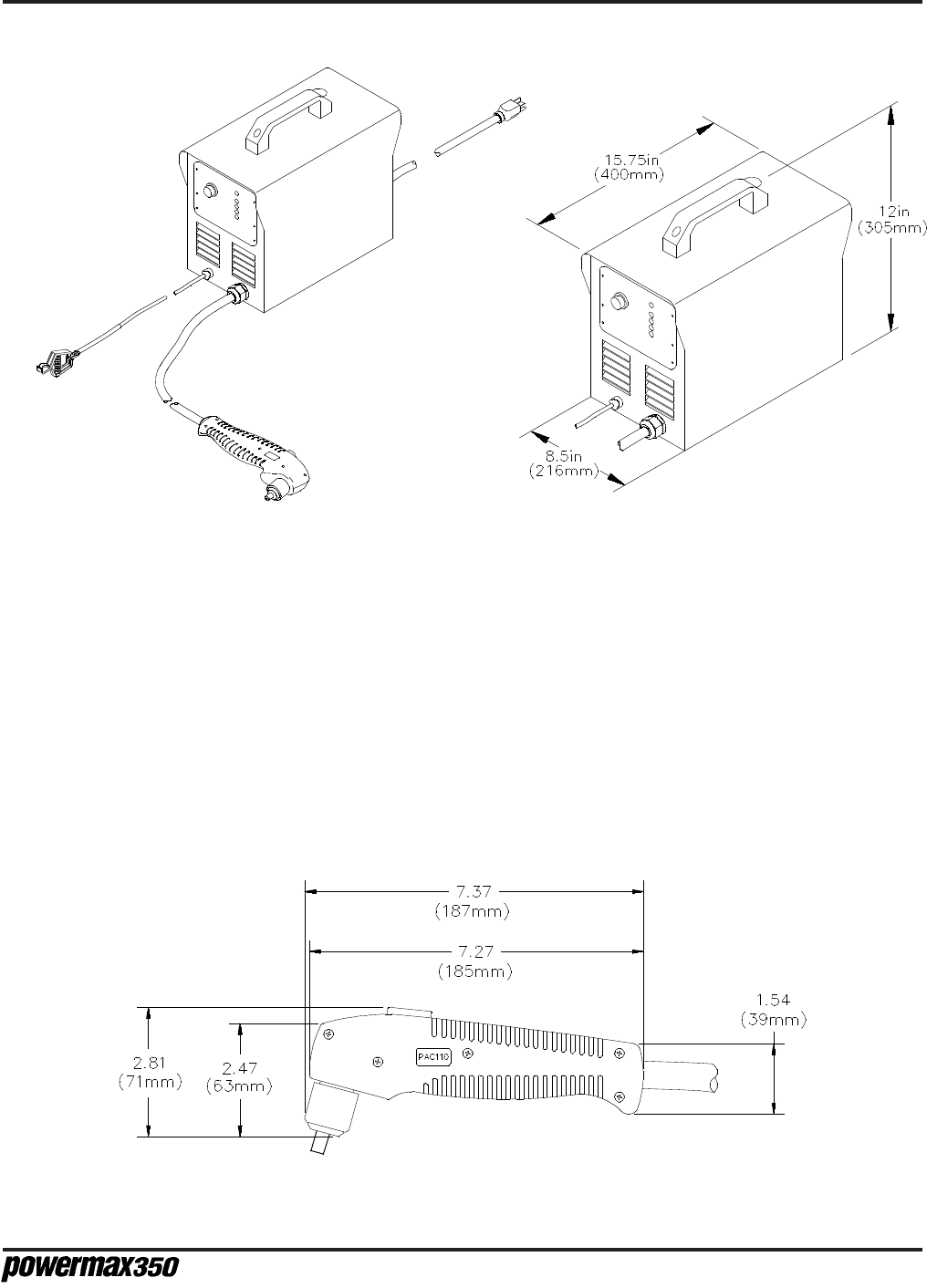
Dimensions ...................................................................See Figure 2-1.
Weight ...........................................................................44 pounds (20 kg)
47 pounds (21.4 kg) with torch
Gas Requirements:
Gas Type.......................................................................Air - clean, dry, oil-free
Supplied Air Pressure and Flowrate..............................70 -120 psi (4.8 - 8.3 bar) @ 270 scfh/4.5 scfm
(127 l/min) supplied to power supply pressure
regulator.
Power Supply Pressure Regulator Setting ....................60 psi (4.1 bar) flowing
1-99
S
PECIFICATIONS
2-3
Operator Manual
Work
Lead
PAC110
Torch
Power
Cord
Powermax350
Figure 2-1 Powermax350 Plasma Cutting System
PAC110 Torch
Recommended Cutting Capacity ..................................1/4 inch (6 mm) @ 25A (35% duty cycle)
Maximum Cutting Capacity ...........................................3/8 inch (10 mm) @ 25A (35% duty cycle)
Severance Cutting Capacity..........................................1/2 inch (12 mm) @ 25A (35% duty cycle)
Gas Flow .......................................................................270 scfh/4.5 scfm at 60 psi (127 l/min at
4.1 bar)
Weight ...........................................................................3 pounds (1.4 kg)
Figure 2-2 PAC110 Torch with Dimensions

2-4
S
PECIFICATIONS
Operator Manual
S MARK
The Powermax350 conforms to standard EN50192. The S mark indicates that the power
supply and torch are suitable for use in environments with increased hazard of electrical shock.
O
I
Direct Current (DC).
Alternating current (AC).
Plasma cutting torch.
AC input power connection.
The terminal for the external protective (earthed) conductor.
A chopper-based power source.
Anode (+) work clamp.
Temperature switch.
Pressure switch.
Plasma torch in the TEST position (cooling and cutting gas exiting nozzle).
The power is on.
The power is off.
Volt/amp curve.
IEC SYMBOLS USED

3-1
S
ETUP
Operator Manual
Section 3 SETUP
In this section:
Upon Receipt ...................................................................................................3-2
Claims ..............................................................................................................3-2
Locating Power Supply ....................................................................................3-2
115/230 Voltage Configurations ....................................................................... 3-2
Input Voltage Selector Switch...................................................................... 3-2
Power Cord Plugs........................................................................................3-2
Grounding ........................................................................................................3-4
Work Cable and Clamp ....................................................................................3-4
Plasma Air Supply ............................................................................................ 3-4
Additional Air Filtration .................................................................................3-5
Air Hose Connection ........................................................................................3-5

3-2
S
ETUP
Operator Manual
UPON RECEIPT
1. Verify that all parts and items on your order have been received. Alert your distributor if any parts or
items are damaged or missing.
2. Inspect the power supply for any physical damage that may have occurred during shipping. If there
is evidence of damage, refer to the
Claims
section below.
All communications regarding this equipment must include the model number and serial number
located on the back of the Powermax350.
3. Before setting up and operating the Powermax350, read the Safety section of this manual.
CLAIMS
Claims for damage during shipment — If your unit was damaged during shipment, you must file a
claim with the carrier. Hypertherm will furnish you with a copy of the bill of lading upon request. If you
need additional assistance, call Customer Service at 1 800 643 0030 in the U.S. and Canada, or your
authorized Hypertherm distributor.
Claims for defective or missing merchandise — All units shipped from Hypertherm undergo rigorous
quality control inspections for defects. If any of the merchandise is defective or missing, call your
authorized Hypertherm distributor. If you need additional assistance, call Customer Service at
1 800 643 0030 in the U.S. and Canada, or your authorized Hypertherm distributor.
LOCATING POWER SUPPLY
Locate the Powermax350 power supply near the 115V or 230V wall receptacle. Allow at least 10
inches (0.25 m) of space at the front and back of the power supply for proper ventilation.
115/230 VOLTAGE CONFIGURATIONS
The 115/230V Powermax350 power supplies are shipped to operate at the following voltages: the 60
Hz units at 115 volts and the 50 Hz units at 230 volts.
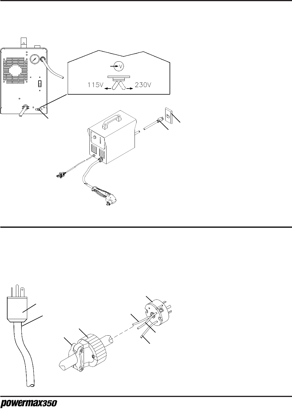
Input Voltage Selector Switch
The Input Voltage Selector switch allows either 115V or 230V to be used as the Powermax350 input
voltage. To set the required voltage, refer to the procedure on the following page (see Fig. 3-1).
Power Cord Plugs
The 115/230V Powermax350 power supplies are shipped with the following power cord configurations:
the 60 Hz units are shipped with a 115V plug on the power cord; the 50 Hz units are shipped without a
plug on the power cord. To operate at 230V, obtain a plug that meets national or local electrical codes.
The plug should be connected to the power cord by a licensed electrician. Also, note that some 115V
receptacles may require a plug that is different from the plug on the power cord. To install the required
plug, refer to the procedure on the following page (see Fig. 3-2). The installed 115V plug and cords
must conform to national or local electrical codes.
8-97
3-3
S
ETUP
Operator Manual
1 Power Cord plug (115V shown)
• Cut cord close to plug.
2 230V plug
3 To load 1 (brass) terminal
4 To load 2 (brass) terminal
5 To ground (green) terminal
6 Outer shell
7 Cord grip
Strip cord insulation back in order to
separate conductors. Strip conductor
insulation back in order to make good
contact with plug terminals. Make
connections, reinstall outer shell and
cord grip and secure with screws.
Do not overtighten.
This procedure is required if the power supply is to be
connected to a 230V receptacle, or to a 115V receptacle
that requires a plug that is different from the plug on the
power cord.
This procedure is necessary if 230V input power is required.
See the procedure in Fig. 3-2 for installing a power cord plug.
2
1
3
2
4
5
6
7
1 Input Voltage Selector switch
2 Retaining screw
• Remove screw and position
switch to select required
voltage.
• Reinstall retaining screw
and tighten to secure switch
in place.
3 Power Cord plug (115V shown)
• If plug does not match
voltage at receptacle or type
of receptacle, install suitable
plug as shown below.
4 115 or 230V receptacle (115V
shown)
• To use rated output (see
specifications in section 2), an
individual branch circuit capable
of carrying 33A, 115V at 35%
duty cycle; or 18A, 230V at 35
duty cycle and protected by fuses
or circuit breakers is required.
Cut cord
here
1
4
3
Figure 3-1 Repositioning Input Voltage Selector Switch
Figure 3-2 Changing Power Cord Plugs
3-4
S
ETUP
Operator Manual
Figure 3-3 Proper Work Clamp
Connection
GROUNDING
To ensure personal safety, proper operation, and to reduce electromagnetic interference (EMI), the
Powermax350 must be properly grounded:
The power supply must be properly grounded through the power cord according to national or local
electrical codes. Single-phase service must be of the 3-wire type with a green or green/yellow wire for
protective earth ground and must comply with national or local electrical requirements. Do not use a
2-wire service! Refer to
Grounding
, in the Safety section.
WORK CABLE AND CLAMP
The work clamp must be attached to the workpiece while cutting. Ensure that the work clamp and the
workpiece make good metal-to-metal contact. Attach the work clamp as close as possible to the area
being cut to reduce exposure to electric and magnetic fields (EMF). Do not attach the work clamp to
the portion of the workpiece to be cut away.
PLASMA AIR SUPPLY
The air supply for the Powermax350 can be supplied as shop compressed air or cylinder compressed
air. A high-pressure regulator on either type of supply must be used and must be capable of delivering
air at 270 scfh/4.5 scfm (127 l/min) at a pressure of 70 psi (4.8 bar) to the filter on the power supply. If
air supply quality is poor, cut speeds decrease, cut quality deteriorates, cutting thickness capability
decreases, and parts life shortens.
WARNING
Do not allow the air inlet pressure to the filter on the power supply to exceed 120 psi
(8.3 bar). The filter bowl may explode if this pressure is exceeded.
3-5
S
ETUP
Operator Manual
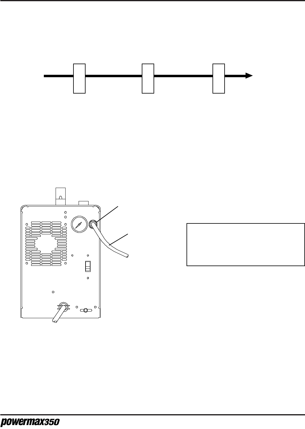
Additional Air Filtration
Use a three-stage coalescing filtration system as shown when site conditions introduce moisture, oil or
other contaminants into the air line.
AIR HOSE CONNECTION
Connect the air hose as follows:
From air
supply
To
Powermax350
Water/particle filter Oil filter Oil vapor filter
Figure 3-4 Recommended Three-Stage Air Filtration System
1
2
To Air Supply
Rear Panel
1 Air fitting
• Install 1/4 NPT quick-disconnect
nipple on to air fitting using a liquid
pipe sealant.
CAUTION: Never use Teflon tape when
installing the nipple or adapters. Bits of
tape can break off and enter the air line
and harm the pressure regulator,
pressure switch and valve.
• Nipple is found in the consumables
box, located in the left side of the power
supply cover.
2 Air hose
• Use a 3/8 inch (9.5 mm) ID inert gas
hose with a 1/4 NPT quick-disconnect
coupler.Connect it to the nipple installed
in step 1.
Adjust the air pressure according to the
procedure in Section 4.
Figure 3-5 Air Supply Connection

O
PERATION
4-1
Operator Manual
Section 4 OPERATION
In this section:
Controls and Indicators ................................................................................... 4-2
Operating Instructions ..................................................................................... 4-3
Operating Tips ................................................................................................. 4-4
Changing Consumable Parts...................................................................... 4-4
Cutting ........................................................................................................ 4-5
Piercing....................................................................................................... 4-6
Operating Data - 25A Consumables ............................................................... 4-7
Common Cutting Faults .................................................................................. 4-8
Duty Cycle and Overheating ........................................................................... 4-8
4-2
O
PERATION
Operator Manual
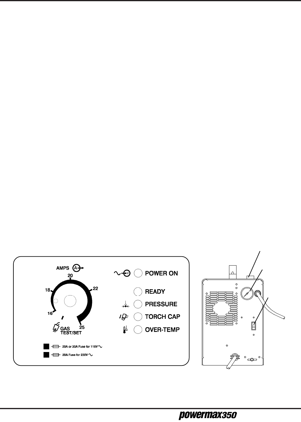
CONTROLS AND INDICATORS
• Green POWER ON LED
When illuminated, indicates that the Power Switch has been set at I (On).
• Green READY LED
When illuminated, indicates that the safety interlocks are satisfied.
• Yellow PRESSURE LED
When illuminated, indicates that the air pressure is below 40 psi (2.8 bar).
• Yellow TORCH CAP LED
When illuminated, indicates that the torch retaining cap is loose.
• Yellow OVER-TEMP LED
When illuminated, indicates that the power supply has overheated.
• AMPS-GAS TEST/SET Adjustment Knob
Adjusts output current between 16 and 25 amps. The GAS TEST/SET position allows adjustment
of the air pressure.
• Pressure Regulator Adjustment Knob
Regulates input gas pressure to the power supply.
• Pressure Gauge
Indicates gas pressure at the power supply.
• ON (I)/OFF (0) Power Switch
Activates the power supply and its control circuits.
Figure 4-1 Powermax350 Controls and Indicators
Green
Yellow
ON (I)/OFF (0)
Power Switch
Pressure
Gauge
Pressure Regulator
Adjustment Knob
Rear
Front

O
PERATION
4-3
Operator Manual
OPERATING INSTRUCTIONS
1. Ensure that the work environment and your clothing meet the safety requirements outlined in
the Safety section. Follow the instructions in the Setup section.
2. Verify that the air supply pressure is set between 70 and 120 psi (4.8 - 8.3 bar).
3. At the rear of the power supply, move the power switch to the ON (I) position. The POWER ON
and READY LEDs should illuminate. The PRESSURE, TORCH CAP and OVER-TEMP LEDs
should remain extinguished.
4. Adjust the pressure regulator to 60 psi (4.1 bar) on the pressure gauge:
• Set the knob to GAS TEST/SET position.
• Pull up on the adjustment knob and turn it to adjust the pressure to 60 psi (4.1 bar).
• Push down the knob to lock it.
5. Adjust the AMPS knob to the desired setting. See
Cut Chart
later in this section.
6. Attach work clamp securely to the workpiece. Do not attach it to the portion that will fall
away.
7. The Powermax350 is now ready to operate. When you are ready to cut, place the tip of the
torch on the workpiece. Press the torch switch to start the arc.
8. The arc will transfer from the torch to the workpiece. Move the torch in the desired direction, at
a speed which will ensure good cut quality. See
Cut Chart
later in this section.
9. When the cut is finished, release the torch switch. Postflow will continue for approximately 10
seconds. The arc can be instantly restarted during postflow by pressing the torch switch.
WARNING
Before operating this system, read the Safety section of this manual thoroughly!
WARNING
The PAC110 torch is an instant-on torch which
produces a plasma arc immediately after the
torch start switch closes. Always hold the hand
torch away from your body as a precaution
against accidental torch firing. Be aware of this
hazardous potential. Failure to do so can result
in serious bodily injury.
Figure 4-2
Proper Work Clamp
Connection
10-97
4-4
O
PERATION
Operator Manual
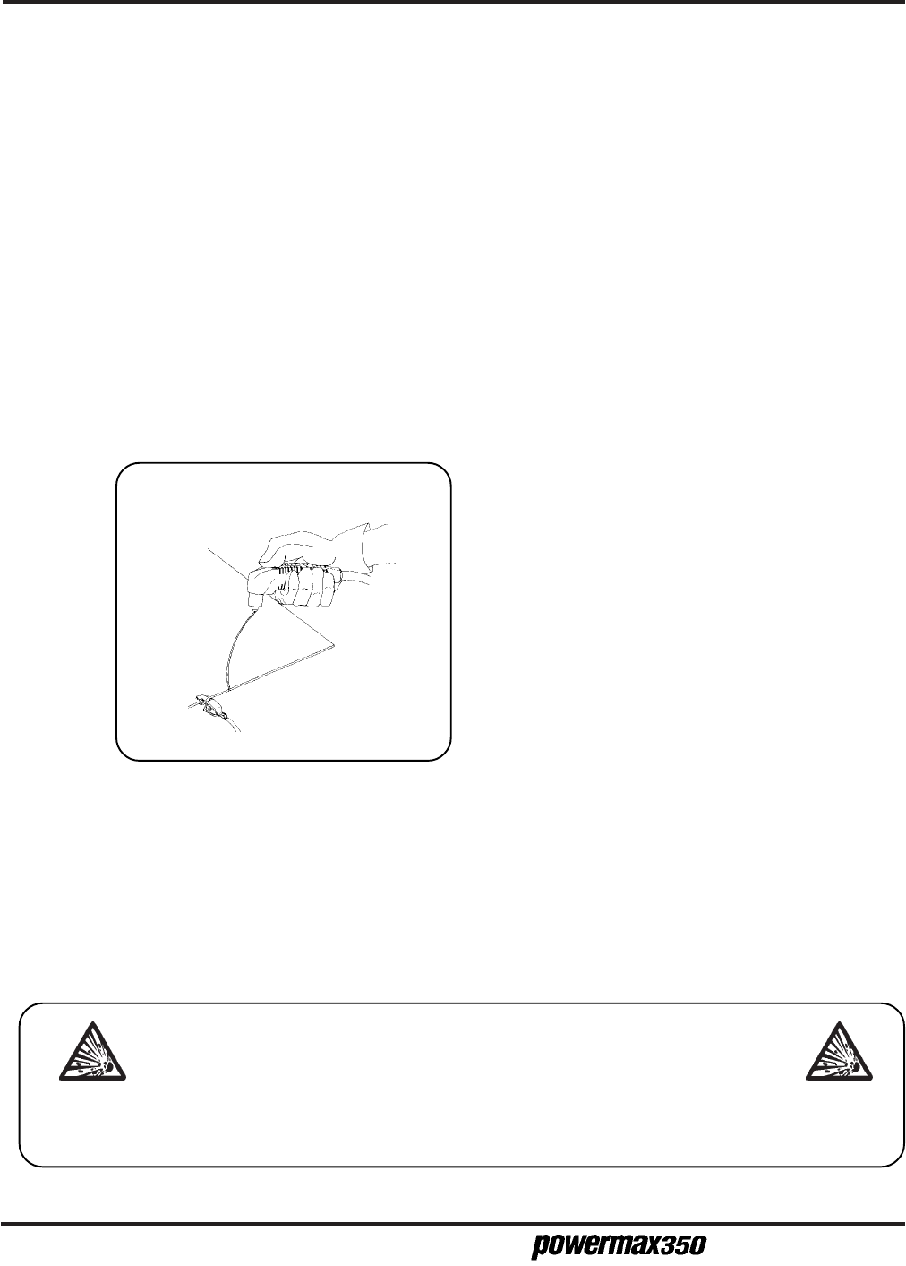
OPERATING TIPS
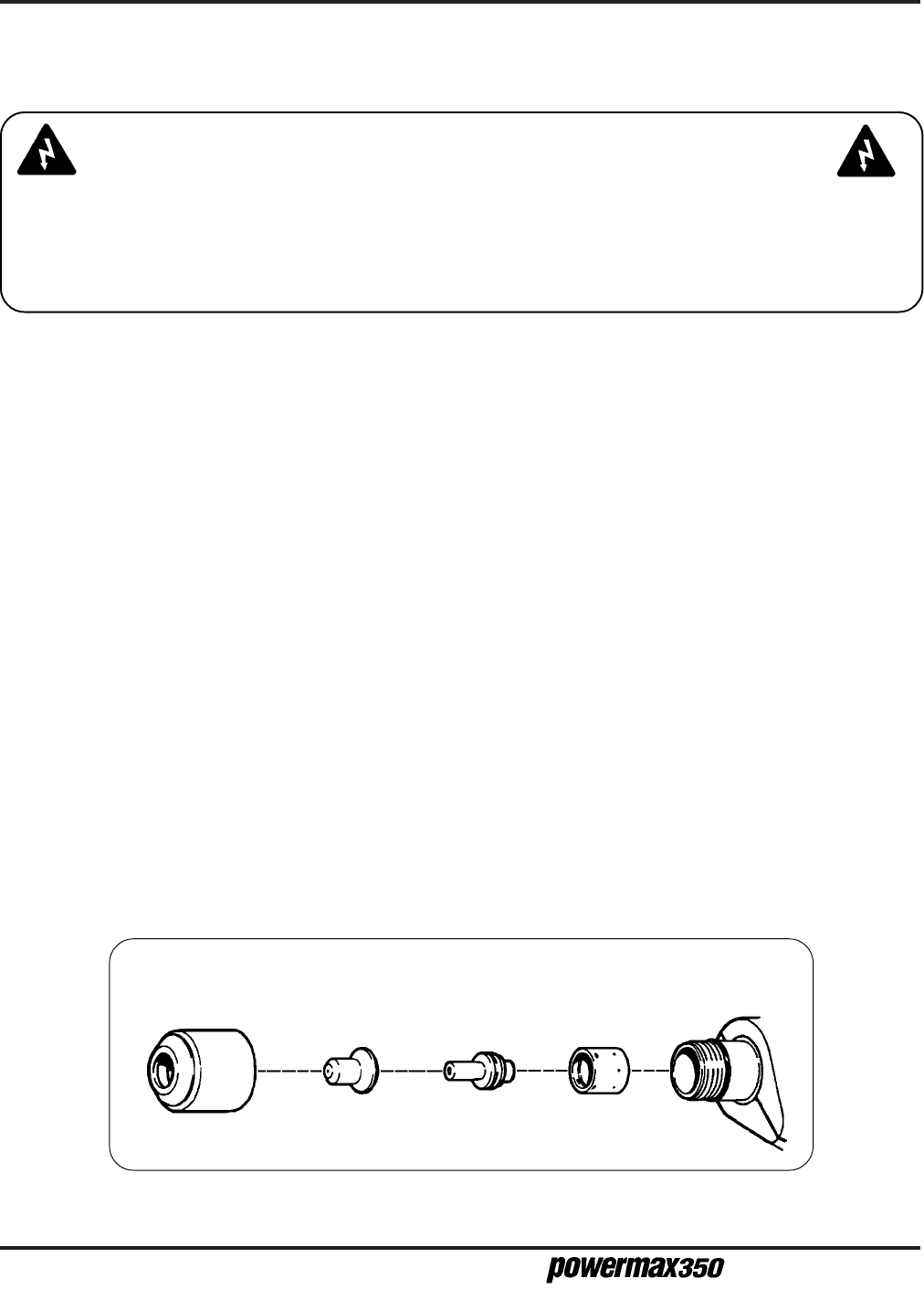
Changing Consumable Parts
Changing the consumable parts requires no tools:
1. Unscrew the retaining cap and the remaining parts will come apart easily. When you unscrew
the retaining cap, you will hear a click. This click is a microswitch (cap-on sensor switch) that
disables the power supply if it is plugged in.
2. Inspect the nozzle for damage or wear. If the hole is worn or oval-shaped, replace it.
3. Inspect the electrode. If the center has a pit more than 1/16 inch (1.6 mm) deep, replace it.
4. Inspect the swirl ring. It should be clean, and the holes along the side should not be plugged. If
it is damaged, replace it.
5. Inspect the O-ring on the torch. It should be lubricated and undamaged. If it is dry, lubricate it
with a thin film of the lubricant provided in the consumable parts kit. If it is damaged, replace it.
6. Replace the parts as shown in Fig. 4-3. Each part fits in only one direction, so you cannot put
the parts in backwards. Also, the torch will not fire if the parts are improperly installed.
7. When the nozzle, electrode and swirl ring are properly in place, replace the retaining cap.
When the retaining cap is tightened, the microswitch will click, indicating that the torch is again
ready for operation. Plug the power supply back in.
The consumable parts are found in a box, located in the left side of the power supply cover.
Swirl Ring
020239
Extended
Electrode
020382
Extended
Nozzle
120504
Retaining Cap
020218
Figure 4-3 Consumable Parts
WARNING
SHOCK HAZARD: Always turn off the power and unplug the cord before changing consum-
able parts. Do not rely on the cap-on sensor switch to remove power. It is provided strictly
for safety backup. In the U.S., use a "lock-out / tag-out" procedure until the service or mainte-
nance work is complete. In other countries, follow appropriate national or local safety proce-
dures.
O
PERATION
4-5
Operator Manual
Cutting
• Do not fire the pilot arc into the air needlessly—doing so causes a significant reduction of the
nozzle and electrode life.
• If arc transfer to the workpiece does not occur within 5 seconds, the pilot arc will shut off. Re-
lease the torch start switch and press it again to reset the pilot arc timer.
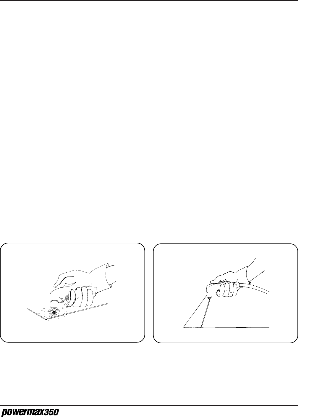
• Start cutting from the edge of the workpiece (Fig. 4-4).
• When cutting, make sure that the sparks are coming out of the bottom of the workpiece. If they
are spraying on top of the workpiece, you are moving the torch too fast, or you do not have
sufficient power to fully penetrate the workpiece.
• Hold the torch lightly on the metal or just above the metal. Holding the torch firmly to the work-
piece causes the shield or nozzle to stick and makes smooth cutting difficult. The arc transfers
to the workpiece once the torch is within 1/8 inch (3 mm) of the workpiece.
• Pulling the torch through the cut is easier than pushing it.
• Hold the torch nozzle at a vertical position and watch the arc as it cuts along the line (Fig. 4-5).
By lightly dragging the nozzle on the workpiece, you can maintain a steady cut. For straight-line
cuts, use any straight edge as a guide.
• When cutting thin material, reduce the amps until you get the best quality cut.
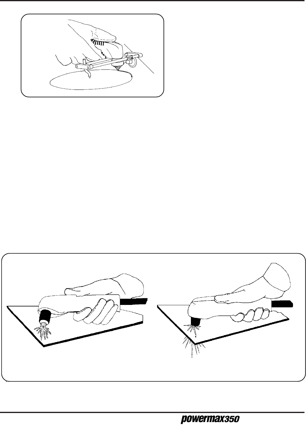
• To cut circles, use a template or a radius cutter attachment (Fig. 4-6).
Figure 4-4 Starting a Cut Figure 4-5 Dragging the Torch
8-97
4-6
O
PERATION
Operator Manual
Figure 4-6
Cutting a Circle
Piercing
• Hold the torch so that the nozzle is approximately 1/16 inch (1.6 mm) away from the workpiece
before firing the torch. This method maximizes the life of the nozzle.
• Hold the torch at an angle to the workpiece away from yourself, then slowly rotate it to an
upright position. This is particularly important when cutting thicker material. Make sure that the
torch is pointed away from you and the people near you to avoid any danger from sparks and
hot metal (Fig. 4-7).
• When the pierce is complete, bring the torch to a perpendicular position and proceed with the
cut.
• Start the cut at an angle rather than in an upright position. This method permits the hot metal to
escape to one side rather than splashing back against the nozzle. This will protect the operator
from the sparks and extend the life of the nozzle.
1. Tilt the torch and press the start button. 2. Rotate the torch to an upright position.
Figure 4-7 Piercing
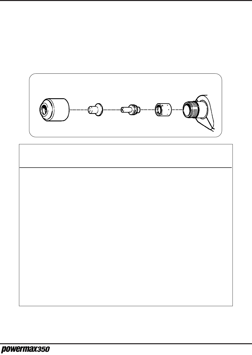
O
PERATION
4-7
Operator Manual
OPERATING DATA - 25A CONSUMABLES
The following recommended settings are for hand-held cutting at 25 amps. Torch-to-work distance for
the following cut charts is 1/16 inch (1.6 mm) for all cuts. The settings are optimized to provide the best
cut angle, least dross and best cut surface finish. Remember that these settings are intended to
provide a good starting point for each different cutting assignment. Every cutting system
requires "fine-tuning" for each cutting application to the materials on site in order to obtain
optimum cut quality.
Swirl Ring
020239
Extended
Electrode
020382
Extended
Nozzle
120504
Retaining Cap
020218
Material Thickness Arc Current Approximate Travel Speed*
(ga. or in.) (mm) (A) (ipm) (mm/min )
Mild Steel 18 GA 1.3 25 70 1775
12 GA 2.8 25 52 1320
1/8 3.6 25 47 1190
3/16 4.8 25 33 825
1/4 6.0 25 17 430
3/8 9.0 25 9 225
Stainless 18 GA 1.3 25 65 1650
Steel 12 GA 2.8 25 48 1215
1/8 3.6 25 41 1040
3/16 4.8 25 27 685
1/4 6.0 25 14 355
3/8 9.0 25 7 175
Aluminum 18 GA 1.3 25 81 2055
12 GA 2.8 25 55 1395
1/8 3.6 25 44 1115
3/16 4.8 25 29 735
1/4 6.0 25 9 225
3/8 9.0 25 5 125
* Recommended travel speeds are 10–20% slower than maximum. These slower speeds will produce optimum
cut quality.

4-8
O
PERATION
Operator Manual
COMMON CUTTING FAULTS
• The workpiece is not totally penetrated. Causes can be:
- The current is too low.
- The cut speed is too high.
- The torch parts are worn.
- The metal being cut is too thick.
- The work clamp is not properly attached to the workpiece.
• Dross forms on the bottom of the cut. Causes can be:
- The cutting speed is too slow.
- The torch parts are worn.
- The metal being cut is too thick.
- The current is too low.
DUTY CYCLE AND OVERHEATING
• The duty cycle is the amount of time, in minutes, that a pilot or plasma arc can remain "on" within a
10-minute period when operating at 104° F (40° C).
- At the 25-amp setting, the arc can remain on 3.5 minutes out of every 10 minutes without
causing the temperature sensors to disable the unit.
- At 20 amps, the duty cycle is 60%, or 6 minutes out of every 10 minutes.
- At 17 amps, the duty cycle increases to 100%.
• If the power supply overheats, the OVER-TEMP LED will illuminate, the arc will shut off and the
cooling fan will continue to run.
• To resume cutting, wait for the OVER-TEMP LED to extinguish (usually 15 minutes or less) and
reduce amperage or duty cycle.
1-99

M
AINTENANCE
/P
ARTS
5-1
Operator Manual
Section 5 MAINTENANCE/PARTS
Introduction ..................................................................................................... 5-2
Routine Maintenance ...................................................................................... 5-2
Trouble LED Indicators.................................................................................... 5-3
Pressure ..................................................................................................... 5-3
Torch Cap ................................................................................................... 5-3
Over-Temp.................................................................................................. 5-3
PAC110 Torch Repair ...................................................................................... 5-4
Parts and Required Tools ........................................................................... 5-4
Remove Torch Main Body .......................................................................... 5-4
Install New Torch Main Body ...................................................................... 5-4
Basic Troubleshooting ..................................................................................... 5-6
Technical Questions ........................................................................................ 5-8
Parts................................................................................................................ 5-8
Powermax350 Hand Systems .................................................................... 5-8
Consumable Parts ...................................................................................... 5-8
PAC110 Torch Assembly and 15 Ft (4.5 M) Torch Lead, 25A ..................... 5-9
PAC110 Torch Assembly and 25 Ft (7.6 M) Torch Lead, 25A ..................... 5-9
In this section:

Operator Manual
5-2
M
AINTENANCE
/P
ARTS
INTRODUCTION
This section contains information for simple maintenance and troubleshooting. A brief parts list is also
included. For higher-level troubleshooting, see
Technical Questions
later in this section.
ROUTINE MAINTENANCE
WARNING
SHOCK HAZARD: Always turn off the power and unplug the cord before changing consum-
able parts. Do not rely on the cap-on sensor switch to remove power. It is provided strictly
for safety backup. In the U.S., use a "lock-out / tag-out" procedure until the service or main-
tenance work is complete. In other countries, follow appropriate national or local safety
procedures.
Under severe conditions, routine maintenance should be performed more frequently.
Before Each Use
• Check the air pressure.
• Check the torch and consumables.
Every Week
• Check the torch cap -on sensor system by listening for the micro-switch to "click" when the
retaining cap is loosened. See Changing Consumable Parts in the Operation section.
3 Months
• Replace damaged or unreadable labels.
• Service the filter and pressure regulator.
• Check the air supply hose.
• Replace any cracked parts.
• Check the torch body and torch lead.
• Replace the torch lead if the insulation is broken.
6 Months
• Blow out or vacuum inside of power supply.
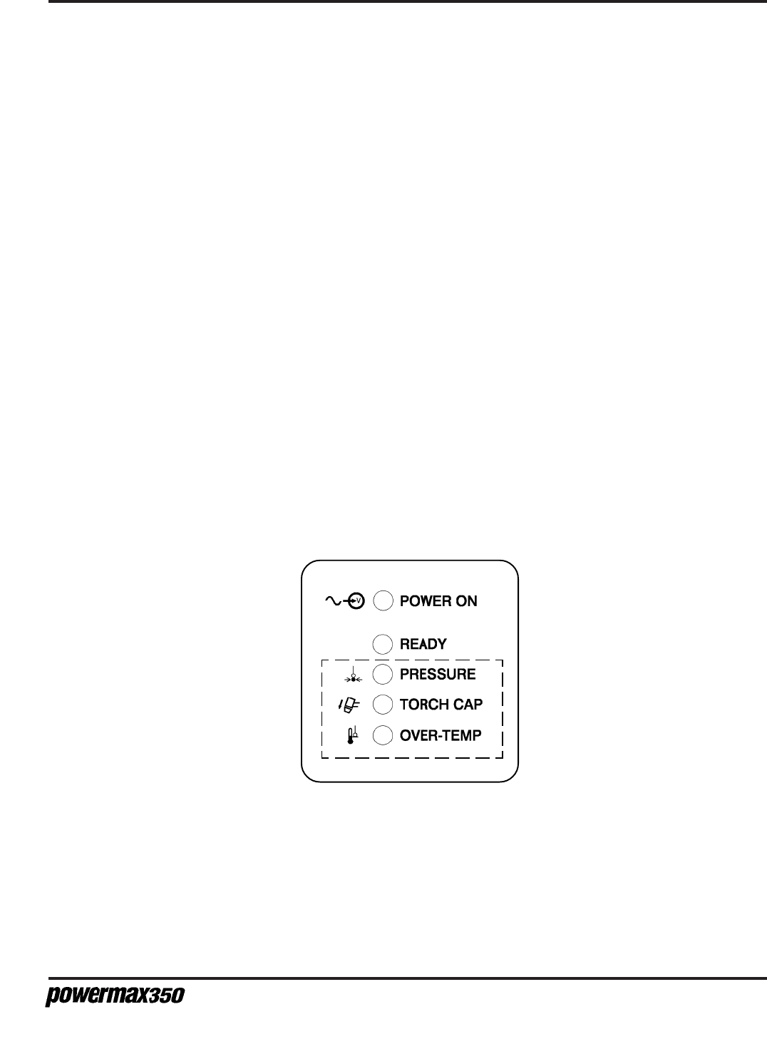
M
AINTENANCE
/P
ARTS
5-3
Operator Manual
Figure 5-1 Trouble LED Indicators
TROUBLE LED INDICATORS
If certain problems occur, the READY LED extinguishes, a trouble LED illuminates and the torch stops
firing.
• PRESSURE LED - Illuminates if air pressure is below 40 psi (2.8 bar).
Turn power Off (O) and check for proper air pressure (see Section 4, Operating Instructions)
• TORCH CAP LED - Illuminates if the retaining cap is loose.
Turn power Off (O) and check that the retaining cap is tight. Whenever the torch cap shut-
down system has been activated, turn the power Off (O) and then On (I) to reset the
system. Check the torch cap shutdown system once a week as follows:
Turn power On (I) and loosen the torch cap.
If shutdown system works properly, READY LED extinguishes and TORCH CAP LED illumi-
nates.
If the shutdown system does not work properly, turn power Off (O) and check for proper air
pressure (see Section 4, Operating Instructions), blocked or leaking hose or loose torch cap.
Check the system by retightening the retaining cap and resetting the power as described above.
• OVER-TEMP LED - Illuminates if power supply overheats. See Duty Cycle and Overheating in
the Operation section.

Operator Manual
5-4
M
AINTENANCE
/P
ARTS
PAC110 TORCH REPAIR
Parts and Required Tools
The PAC110 torch can be repaired in the field by removing the torch main body from the torch assem-
bly and installing a new torch main body and a plastic cinch strap (Tyrap). To perform the repair, the
following customer-supplied tools are required:
• #1 Phillips-head screwdriver
• 7/16" open-end wrench
• Wire cutters
• Crimping tool
WARNING
SHOCK HAZARD: Always turn off power, unplug cord from wall before working on the
torch. In the U.S., use a "lock-out/tag-out" procedure until the service or maintenance
work is complete. In other countries, follow appropriate local or national safety proce-
dures.
Remove Torch Main Body
To disassemble and repair the torch, refer to Figure 5-2 and perform the following procedure:
1. Remove the five screws which secure the handle halves together.
2. Remove the torch main body and torch switch from the handle halves.
3. Disconnect the cinch strap (Tyrap).
4. Cut the four white wires connecting the torch lead to the plunger. Cut the wires at the butt splice.
5. Cut the two blue wires connecting the torch lead to the microswitch. Cut the wires at the butt
splices.
6. Cut the two red wire connecting the torch lead to the pilot arc lead. Cut the wire at the butt splice.
7. Disconnect the torch main body and torch lead gas fitting using the 7/16" open-end wrench.
Install New Torch Main Body
To install the new torch, reverse the removal procedure:
1. While holding the torch main body to keep the wires from twisting, connect the body assembly and
the torch lead gas fitting using the 7/16" open-end wrench.
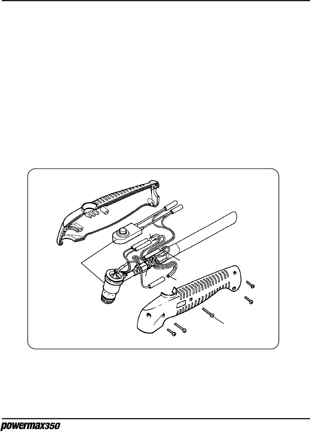
M
AINTENANCE
/P
ARTS
5-5
Operator Manual
2. Connect the two red wire from the torch lead to the butt splice connecting the red wire to the pilot
arc fitting using the crimping tool.
3. Connect the two blue wires from the torch lead to the butt splices connecting the white wires to the
microswitch using the crimping tool.
4. Connect the four white wires from the torch lead to the butt splice connecting the black plunger wire
to the torch main body using the crimping tool.
5. Connect the cinch strap (Tyrap) as shown.
6. Install the torch main body assembly and torch switch into one of the handle halves. While position-
ing the handle halves together, be careful not to pinch any wires. Be especially careful around
the torch switch retainers.
7. Replace the five screws to secure the handle halves together. If the seams do not fit together
tightly, remove the screws and check for pinched wires.
2
3
1
4
5
6
Figure 5-2 PAC110 Torch Repair

Operator Manual
5-6
M
AINTENANCE
/P
ARTS
BASIC TROUBLESHOOTING
Problem Cause/Solution
1. No pilot arc; difficulty in establishing an arc.
2. No cutting output; POWER ON, READY,
PRESSURE, TORCH CAP and OVER-TEMP
LEDs extinguished; fan not running.
3. No cutting output; POWER ON and READY
LEDs illuminated; PRESSURE, TORCH CAP and
OVER-TEMP LEDs extinguished; fan running.
4. No cutting output; POWER ON LED
illuminated; READY, PRESSURE, TORCH CAP
and OVER-TEMP LEDs extinguished; fan
running.
5. No control of cutting output.
6. No air flow; POWER ON and READY LEDs
illuminated; PRESSURE, TORCH CAP and
OVER-TEMP LEDs extinguished; fan running.
7. PRESSURE LED illuminated; READY LED
extinguished.
1.1 Clean or replace worn consumables as
necessary.
1.2 Check for proper installation of swirl ring.
1.3 Refer to Service Manual IM-292 (802920) for
more detailed troubleshooting.
2.1 Place the Power switch to On(I)
2.2 Plug in the power cord.
2.3 Check line disconnect fuses and replace if
needed or reset circuit breakers.
2.4 Refer to Service Manual IM-292 (802920) for
more detailed troubleshooting.
3.1 Check that the work clamp is connected.
3.2 Clean or replace worn consumables as
necessary.
3.3 Refer to Service Manual IM-292 (802920) for
more detailed troubleshooting.
4.1 Reset the power switch.
4.2 Refer to Service Manual IM-292 (802920) for
more detailed troubleshooting.
5.1 Check position of input voltage selector
switch S2.
5.2 Refer to Service Manual IM-292 (802920) for
more detailed troubleshooting.
6.1 Refer to Service Manual IM-292 (802920) for
more detailed troubleshooting.
7.1 Check for correct air pressure (see Section
4, Operation Instructions).
7.2 Check for sufficient air supply pressure (see
Section 2, Specifications).

M
AINTENANCE
/P
ARTS
5-7
Operator Manual
Problem Cause/Solution
8. TORCH CAP LED illuminated; READY LED
extinguished.
9. OVER-TEMP LED illuminated; READY LED
extinguished.
10. Fan not running; POWER ON and READY
LEDs illuminated.
11. PRESSURE, TORCH CAP and OVER-TEMP
LEDs not working.
7.3 Refer to Service Manual IM-292 (802920) for
more detailed troubleshooting.
8.1 Check torch retaining cap to ensure it is tight.
8.2 Refer to Service Manual IM-292 (802920) for
more detailed troubleshooting.
9.1 Thermostat in power supply is open
(overheating). Allow the fan to run; the
thermostat closes when the unit has cooled
(see Section 4, Duty Cycle and
Overheating).
9.2 Refer to Service Manual IM-292 (802920) for
more detailed troubleshooting.
10.1 Refer to Service Manual IM-292 (802920) for
more detailed troubleshooting.
11.1 Refer to Service Manual IM-292 (802920) for
more detailed troubleshooting.

Operator Manual
5-8
M
AINTENANCE
/P
ARTS
TECHNICAL QUESTIONS
If you are unable to fix the problem with your Powermax350 by following this basic troubleshooting
guide or if you need further assistance:
1. Call your distributor. He/she will be able to help you, or refer you to an authorized Hypertherm
repair facility.
2. Call Hypertherm's Technical Service group at 1 800 643 9878 or the nearest Hypertherm office,
listed in the front of this manual.
3. See the Powermax350 Service Manual IM-292 (802920) for wiring diagrams, higher level
troubleshooting and more parts list information.
PARTS
Powermax350 Hand Systems
070052 115/230 VAC, 1 Phase, 60 Hz 15 ft (4.5 M)
070053 115/230 VAC, 1 Phase, 60 Hz 25 ft (7.6 M)
070055 CE 115/230 VAC, 1 Phase, 50 Hz 15 ft (4.5 M)
070056 CE 115/230 VAC, 1 Phase, 50 Hz 25 ft (7.6 M)
Consumable Parts
The consumable parts are found in a box, located in the left side of the power supply cover.
Part Number Description
020239................................................................Ring, Swirl
020382.................................................Electrode, Extended
120504............................................ Nozzle, Extended, 25A
020218......................................................... Cap, Retaining
Swirl Ring
020239
Extended
Electrode
020382
Extended
Nozzle
120504
Retaining Cap
020218
Figure 5-3 Consumable Parts
5-98
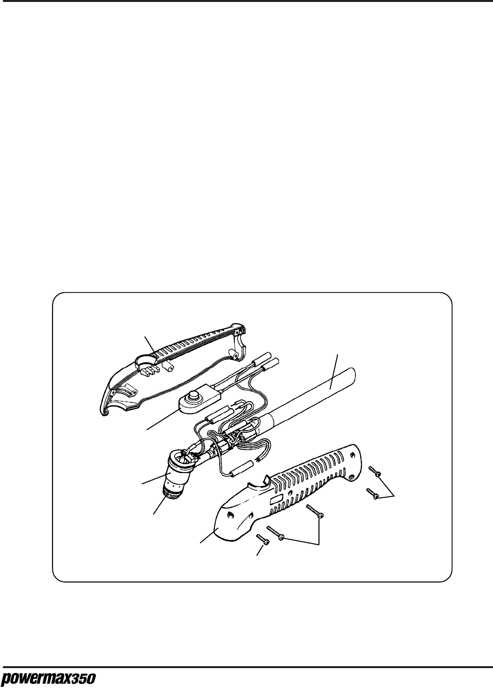
M
AINTENANCE
/P
ARTS
5-9
Operator Manual
PAC110 Torch Assembly and 15 ft (4.5 m) Torch Lead, 25A - 070057
PAC110 Torch Assembly and 25 ft (7.6 m) Torch Lead, 25A - 070058
Part Number Description
001192 ................................. Handle, PAC110
075339 ................................. Screws (3), P/S, # 4 X 1/2, PH, RND, S/B
075341 ................................. Screws (2), P/S, # 4 X 3/4, PH, RND, S/B
005094 ................................. Switch, Torch Pushbutton
020239* ................................ Ring, Swirl
020382* ................................ Electrode, Extended
120504* ................................ Nozzle, Extended, 25A
020218* ................................ Cap, Retaining
020588 ................................. Torch Main Body with Switch, PAC110
044016 ....................................... O-Ring: BUNA 90 Duro .614X.070
029241 ................................. Torch Lead, 15 ft (4.5 m)
029257 ................................. Torch Lead, 25 ft (7.6 m)
* See Fig. 5-3 for consumable parts.
Handle
001192
Torch Lead
029241, 15 ft (4.5 m)
029257, 25 ft (7.6 m)
Torch
Pushbutton
Switch
005094
Handle
001192
O-Ring
044016
Screw
075339
Screw (2)
075341
Screw (2)
075339
Figure 5-4 PAC110 Torch Assembly and Torch Lead
Torch Main
Body with Switch
020588
