
Powermax45 XP
®
Plasma Arc Cutting System
Operator Manual
809240 | Revision 4 | English
Powermax, Duramax, FastConnect, Smart Sense, HyAccess, FlushCut, CopperPlus, and Hypertherm are trademarks of
Hypertherm, Inc. and may be registered in the United States and other countries. All other trademarks are the property of their
respective holders.
Environmental stewardship is one of Hypertherm’s core values, and it is critical to our success and our customers’ success. We
are striving to reduce the environmental impact of everything we do. For more information:www.hypertherm.com/environment.
© 2020 Hypertherm, Inc.
Register your new Hypertherm system
Benefits of registration
5 Safety: Registration allows us to contact you in the unlikely event a safety or quality notification
is required.
5 Education: Registration gives you free access to online product training content via the
Hypertherm Cutting Institute.
5 Confirmation of ownership: Registration can serve as proof of purchase in case of an
insurance loss.
Go to www.hypertherm.com/registration for easy and fast registration.
If you experience any problems with the product registration process, please contact
For your records
Serial number: __________________________________________________________________________
Purchase date: __________________________________________________________________________
Distributor: _____________________________________________________________________________
_______________________________________________________________________________________
_______________________________________________________________________________________
Maintenance notes: ______________________________________________________________________
_______________________________________________________________________________________
_______________________________________________________________________________________
_______________________________________________________________________________________
_______________________________________________________________________________________

Hypertherm Europe B.V.
Vaartveld 9, 4704 SE
Roosendaal, Nederland
31 165 596907 Tel
31 165 596901 Fax
31 165 596908 Tel (Marketing)
31 (0) 165 596900 Tel (Technical Service)
00 800 4973 7843 Tel (Technical Service)
(Technical Service Email)
Hypertherm (Shanghai) Trading Co., Ltd.
B301, 495 ShangZhong Road
Shanghai, 200231
PR China
86-21-80231122 Tel
86-21-80231120 Fax
86-21-80231128 Tel (Technical Service)
(Technical Service Email)
South America & Central America: Hypertherm Brasil Ltda.
Rua Bras Cubas, 231 – Jardim Maia
Guarulhos, SP – Brasil
CEP 07115-030
55 11 2409 2636 Tel
[email protected] (Technical Service Email)
Hypertherm Korea Branch
#3904. APEC-ro 17. Heaundae-gu. Busan.
Korea 48060
82 (0)51 747 0358 Tel
82 (0)51 701 0358 Fax
[email protected] (Marketing Email)
TechSupportAPA[email protected]
(Technical Service Email)
Hypertherm Pty Limited
GPO Box 4836
Sydney NSW 2001, Australia
61 (0) 437 606 995 Tel
61 7 3219 9010 Fax
[email protected] (Main Office Email)
TechSupportAPA[email protected]
(Technical Service Email)
Hypertherm (India) Thermal Cutting Pvt. Ltd
A-18 / B-1 Extension,
Mohan Co-Operative Industrial Estate,
Mathura Road, New Delhi 110044, India
91-11-40521201/ 2/ 3 Tel
91-11 40521204 Fax
HTIndia.info@hypertherm.com (Main Office Email)
TechSupportAPA[email protected]
(Technical Service Email)
Hypertherm, Inc.
Etna Road, P.O. Box 5010
Hanover, NH 03755 USA
603-643-3441 Tel (Main Office)
603-643-5352 Fax (All Departments)
[email protected] (Main Office Email)
800-643-9878 Tel (Technical Service)
[email protected] (Technical Service Email)
800-737-2978 Tel (Customer Service)
customer.service@hypertherm.com (Customer Service Email)
866-643-7711 Tel (Return Materials Authorization)
877-371-2876 Fax (Return Materials Authorization)
[email protected] (RMA email)
Hypertherm México, S.A. de C.V.
Avenida Toluca No. 444, Anexo 1,
Colonia Olivar de los Padres
Delegación Álvaro Obregón
México, D.F. C.P. 01780
52 55 5681 8109 Tel
52 55 5683 2127 Fax
Soporte.Tecnico@hypertherm.com (Technical Service Email)
Hypertherm Plasmatechnik GmbH
Sophie-Scholl-Platz 5
63452 Hanau
Germany
00 800 33 24 97 37 Tel
00 800 49 73 73 29 Fax
31 (0) 165 596900 Tel (Technical Service)
00 800 4973 7843 Tel (Technical Service)
[email protected] (Technical Service Email)
Hypertherm (Singapore) Pte Ltd.
82 Genting Lane
Media Centre
Annexe Block #A01-01
Singapore 349567, Republic of Singapore
65 6841 2489 Tel
65 6841 2490 Fax
[email protected] (Marketing Email)
TechSupportAPA[email protected] (Technical Service Email)
Hypertherm Japan Ltd.
Level 9, Edobori Center Building
2-1-1 Edobori, Nishi-ku
Osaka 550-0002 Japan
81 6 6225 1183 Tel
81 6 6225 1184 Fax
HT[email protected] (Main Office Email)
T[email protected] (Technical Service Email)
For training and education resources, go to the Hypertherm Cutting Institute (HCI) online at
www.hypertherm.com/hci.

ENGLISH
WARNING! Before operating any Hypertherm equipment, read the safety
instructions in your product’s manual, the Safety and Compliance Manual
(80669C), Waterjet Safety and Compliance Manual (80943C), and
Radio Frequency Warning Manual (80945C). Failure to follow safety
instructions can result in personal injury or in damage to equipment.
Copies of the manuals may accompany the product in electronic and printed
formats. You can also obtain copies of the manuals, in all languages available
for each manual, from the “Documents library” at
www.hypertherm.com.
BG (БЪЛГAPCКИ/BULGARIAN)
ПРЕДУПРЕЖДЕНИЕ! Преди да работите с което и да е оборудване
Hypertherm, прочетете инструкциите за безопасност в ръководството
на вашия продукт, „Инструкция за безопасност и съответствие“ (80669C),
„Инструкция за безопасност и съответствие на Waterjet“ (80943С)
и „Инструкция за предупреждение за радиочестота“ (80945С).
Копия на ръководствата може да придружават продукта в електронен
и в печатен формат. Можете да получите копия на ръководствата,
предлагани на всички езици, от „Documents library“ (Библиотека
за документи) на адрес
www.hypertherm.com.
CS (ČESKY/CZECH)
VAROVÁNÍ! Před uvedením jakéhokoli zařízení Hypertherm do provozu
si přečtěte bezpečnostní pokyny v příručce k produktu a v Manuálu pro
bezpečnost a dodržování předpisů (80669C), Manuálu pro bezpečnost
a dodržování předpisů při řezání vodním paprskem (80943C) a Manuálu
varování ohledně rádiových frekvencí (80945C).
Kopie příruček a manuálů mohou být součástí dodávky produktu,
a to v elektronické i tištěné formě. Kopie příruček a manuálů ve všech
jazykových verzích, v nichž byly dané příručky a manuály vytvořeny, naleznete
v „Knihovně dokumentů“ na webových stránkách
www.hypertherm.com.
DA (DANSK/DANISH)
ADVARSEL! Inden Hypertherm udstyr tages i brug skal
sikkerhedsinstruktionerne i produktets manual og i Manual om sikkerhed
og overholdelse af krav (80669C), Manual om sikkerhed og overholdelse
af krav for vandstråleskæring (80943C), og Manual om radiofrekvensadvarsel
(80945C), gennemlæses.
Kopier af manualerne kan ledsage produktet i elektroniske og trykte formater.
Du kan også få kopier af manualer, på alle sprog der er til rådighed for hver
manuel, fra “Dokumentbiblioteket” på
www.hypertherm.com.
DE (DEUTSCH/GERMAN)
WARNUNG! Bevor Sie ein Hypertherm-Gerät in Betrieb nehmen, lesen Sie
bitte die Sicherheitsanweisungen in Ihrer Bedienungsanleitung, das Handbuch
für Sicherheit und Übereinstimmung (80669C), das Handbuch für Sicherheit
und Compliance bei Wasserstrahl-Schneidanlagen (80943C) und das
Handbuch für Hochfrequenz-Warnung (80945C).
Bedienungsanleitungen und Handbücher können dem Gerät in elektronischer
Form oder als Druckversion beiliegen. Alle Handbücher und Anleitungen
können in den jeweils verfügbaren Sprachen auch in der
„Dokumente-Bibliothek“ unter
www.hypertherm.com heruntergeladen werden.
ES (ESPAÑOL/SPANISH)
¡ADVERTENCIA! Antes de operar cualquier equipo Hypertherm, lea
las instrucciones de seguridad del manual de su producto, del Manual
de seguridad y cumplimiento (80669C), del Manual de seguridad
y cumplimiento en corte con chorro de agua (80943C) y del Manual
de advertencias de radiofrecuencia (80945C).
Pueden venir copias de los manuales en formato electrónico e impreso
junto con el producto. También se pueden obtener copias de los manuales,
en todos los idiomas disponibles para cada manual, de la “Biblioteca
de documentos” en
www.hypertherm.com.
ET (EESTI/ESTONIAN)
HOIATUS! Enne Hyperthermi mis tahes seadme kasutamist lugege läbi toote
kasutusjuhendis olevad ohutusjuhised ning Ohutus- ja vastavusjuhend
(80669C), Veejoa ohutuse ja vastavuse juhend (80943C) ja Raadiosageduse
hoiatusjuhend (80945C). Ohutusjuhiste eiramine võib põhjustada vigastusi
ja kahjustada seadmeid.
Juhiste koopiad võivad olla tootega kaasas elektroonilises ja trükivormingus.
Juhiste koopiaid kõigis iga käsiraamatu jaoks saadaolevas keeles saate
hankida ka „Documents library (dokumentide raamatukogust)” lehel
www.hypertherm.com.
FI (SUOMI/FINNISH)
VAROITUS! Ennen minkään Hypertherm-laitteen käyttöä lue
tuotteen käyttöoppaassa olevat turvallisuusohjeet, turvallisuuden
ja vaatimustenmukaisuuden käsikirja (80669C), vesileikkauksen
turvallisuuden ja vaatimustenmukaisuuden käsikirja (80943C)
ja radiotaajuusvaroitusten käsikirja (80945C).
Käyttöoppaiden kopiot voivat olla tuotteen mukana elektronisessa
ja tulostetussa muodossa. Voit saada käyttöoppaiden kopiot kaikilla
kielillä ”latauskirjastosta”, joka on osoitteessa
www.hypertherm.com.
FR (FRANÇAIS/FRENCH)
AVERTISSEMENT! Avant d’utiliser tout équipement Hypertherm, lire les
consignes de sécurité dumanuel de votre produit, duManuel de sécurité
et de conformité (80669C), du Manuel de sécurité et de conformité du jet
d’eau (80943C) et du Manuel d'avertissement relatif aux radiofréqunces
(80945C).
Des copies de ces manuels peuvent accompagner le produit en format
électronique et papier. Vous pouvez également obtenir des copies de chaque
manuel dans toutes les langues disponibles à partir de la «Bibliothèque
de documents» sur
www.hypertherm.com.
GR (ΕΛΛΗΝΙΚΆ/GREEK)
ΠΡΟΕΙΔΟΠΟΙΗΣΗ! Πριν θέσετε σε λειτουργία οποιονδήποτε εξοπλισμό της
Hypertherm, διαβάστε τις οδηγίες ασφαλείας στο εγχειρίδιο του προϊόντος
και στο εγχειρίδιο ασφάλειας και συμμόρφωσης (80669C), στο εγχειρίδιο
ασφάλειας και συμμόρφωσης του waterjet (80943C) και στο εγχειρίδιο
προειδοποιήσεων για τις ραδιοσυχνότητες (80945C).
Αντίγραφα των εγχειριδίων μπορεί να συνοδεύουν το προϊόν σε ηλεκτρονική
και έντυπη μορφή. Μπορείτε, επίσης, να λάβετε αντίγραφα των εγχειριδίων
σε όλες τις γλώσσες που διατίθενται για κάθε εγχειρίδιο από την ψηφιακή
βιβλιοθήκη εγγράφων (Documents library) στη διαδικτυακή τοποθεσία
www.hypertherm.com.
HU (MAGYAR/HUNGARIAN)
VIGYÁZAT! Mielőtt bármilyen Hypertherm berendezést üzemeltetne,
olvassa el a biztonsági információkat a termék kézikönyvében, a Biztonsági
és szabálykövetési kézikönyvben (80669C), a Vízsugaras biztonsági
és szabálykövetési kézikönyvben (80943C) és a Rádiófrekvenciás
figyelmeztetéseket tartalmazó kézikönyvben (80945C).
A termékhez a kézikönyv példányai elektronikus és nyomtatott formában
is mellékelve lehetnek. A kézikönyvek példányai (minden nyelven)
a
www.hypertherm.com weboldalon a „Documents library”
(Dokumentum könyvtár) részben is beszerezhetők.
ID (BAHASA INDONESIA/INDONESIAN)
PERINGATAN! Sebelum mengoperasikan peralatan Hypertherm, bacalah
petunjuk keselamatan dalam manual produk Anda, Manual Keselamatan dan
Kepatuhan (80669C), Manual Keselamatan dan Kepatuhan Jet Air (80943C),
dan Manual Peringatan Frekuensi Radio (80945C). Kegagalan mengikuti
petunjuk keselamatan dapat menyebabkan cedera pribadi atau kerusakan
pada peralatan.
Produk mungkin disertai salinan manual dalam format elektronik maupun cetak.
Anda juga dapat memperoleh salinan manual, dalam semua bahasa yang
tersedia untuk setiap manual, dari "Perpustakaan dokumen"
di
www.hypertherm.com.

IT (ITALIANO/ITALIAN)
AVVERTENZA! Prima di usare un’attrezzatura Hypertherm, leggere le istruzioni
sulla sicurezza nel manuale del prodotto, nel Manuale sulla sicurezza e la
conformità (80669C), nel Manuale sulla sicurezza e la conformità Waterjet
(80943C) e nel Manuale di avvertenze sulla radiofrequenza(80945C).
Il prodotto può essere accompagnato da copie elettroniche e cartacee
del manuale. È anche possibile ottenere copie del manuale, in tutte le lingue
disponibili per ogni manuale, dall’“Archivio documenti” all’indirizzo
www.hypertherm.com.
JA ( /JAPANESE)
! Hypertherm
(80669C)
(80943C) (80945C)
www.hypertherm.com
KO (한국어/KOREAN)
경고! Hypertherm 장비를 사용하기 전에 제품 설명서와 안전 및 규정 준수
설명서(80669C), 워터젯 안전 및 규정 준수 설명서(80943C) 그리고 무선
주파수 경고 설명서(80945C)에 나와 있는 안전 지침을 읽으십시오.
전자 형식과 인쇄된 형식으로 설명서 사본이 제품과 함께 제공될
수 있습니다.
www.hypertherm.com 의 'Documents library (문서라이브러리)'
에서도모든언어로이용할수있는설명서사본을얻을수있습니다.
NE (NEDERLANDS/DUTCH)
WAARSCHUWING! Lees voordat u Hypertherm-apparatuur gebruikt
de veiligheidsinstructies in de producthandleiding, in de Veiligheids-
en nalevingshandleiding (80669C) in de Veiligheids- en nalevingshandleiding
voor waterstralen (80943C) en in de Waarschuwingshandleiding
radiofrequentie (80945C).
De handleidingen kunnen in elektronische en gedrukte vorm met
het product worden meegeleverd. De handleidingen, elke handleiding
beschikbaar in alle talen, zijn ook verkrijgbaar via de “Documentenbibliotheek”
op
www.hypertherm.com.
NO (NORSK/NORWEGIAN)
ADVARSEL! Før du bruker noe Hypertherm-utstyr, må du lese
sikkerhetsinstruksjonene i produktets håndbok, håndboken om sikkerhet
og samsvar (80669C), håndboken om vannjet sikkerhet og samsvar
(80943C), og håndboken om radiofrekvensadvarsler (80945C).
Eksemplarer av håndbøkene kan medfølge produktet i elektroniske og trykte
utgaver. Du kan også få eksemplarer av håndbøkene i alle tilgjengelige språk
for hver håndbok fra dokumentbiblioteket på
www.hypertherm.com.
PL (POLSKI/POLISH)
OSTRZEŻENIE! Przed rozpoczęciem obsługi jakiegokolwiek systemu
firmy Hypertherm należy się zapoznać z instrukcjami bezpieczeństwa
zamieszczonymi w podręczniku produktu, w podręczniku bezpieczeństwa
i zgodności (80669C), podręczniku bezpieczeństwa i zgodności systemów
strumienia wody (80943C) oraz podręczniku z ostrzeżeniem o częstotliwości
radiowej (80945C).
Do produktu mogą być dołączone kopie podręczników w formacie
elektronicznym i drukowanym. Kopie podręczników, wkażdym udostępnionym
języku, można również znaleźć w„Bibliotece dokumentów” pod adresem
www.hypertherm.com.
PT (PORTUGUÊS/PORTUGUESE)
ADVERTÊNCIA! Antes de operar qualquer equipamento Hypertherm,
leia as instruções de segurança no manual do seu produto, no Manual
de Segurança e de Conformidade (80669C), no Manual de Segurança
e de Conformidade do Waterjet (80943C) e no Manual de Advertência
de radiofrequência (80945C).
Cópias dos manuais podem acompanhar os produtos nos formatos eletrônico
e impresso. Também é possível obter cópias dos manuais em todos os idiomas
disponíveis para cada manual na “Biblioteca de documentos” em
www.hypertherm.com.
RO (ROMÂNĂ/ROMANIAN)
AVERTIZARE! Înainte de utilizarea oricărui echipament Hypertherm, citiți
instrucțiunile de siguranță din manualul produsului, manualul de siguranță
și conformitate (80669C), manualul de siguranță și conformitate Waterjet
(80943C) și din manualul de avertizare privind radiofrecvența (80945C).
Produsul poate fi însoțit de copii ale manualului în format tipărit și electronic.
De asemenea, dumneavoastră puteţi obţine copii ale manualelor, în toate limbile
disponibile pentru fiecare manual, din cadrul secţiunii „Bibliotecă documente”
aflată pe site-ul
www.hypertherm.com.
RU (PУССКИЙ/RUSSIAN)
БЕРЕГИСЬ! Перед работой с любым оборудованием Hypertherm
ознакомьтесь с инструкциями по безопасности, представленными
в руководстве, которое поставляется вместе с продуктом,
в Руководстве по безопасности и соответствию (80669С),
в Руководстве по безопасности и соответствию для водоструйной
резки (80943C) и Руководстве по предупреждению о радиочастотном
излучении (80945С).
Копии руководств, которые поставляются вместе с продуктом, могут быть
представлены в электронном и бумажном виде. Копии руководств на всех
языках, на которые переведено то или иное руководство, можно также
загрузить в разделе «Библиотека документов» на веб-сайте
www.hypertherm.com.
SK (SLOVENČINA/SLOVAK)
VÝSTRAHA! Pred použitím akéhokoľvek zariadenia od spoločnosti Hypertherm
si prečítajte bezpečnostné pokyny v návode na obsluhu vášho zariadenia
avManuáli o bezpečnosti a súlade s normami (80669C), Manuáli
o bezpečnosti a súlade snormami pre systém rezania vodou (80943C)
avManuáli sinformáciami orádiofrekvencii (80945C).
Kópia návodu, ktorá je dodávaná s produktom, môže mať elektronickú
alebo tlačenú podobu. Kópie návodov, vo všetkých dostupných jazykoch,
sú k dispozícii aj v sekcii z „knižnice Dokumenty“ na
www.hypertherm.com.
SL (SLOVENŠČINA/SLOVENIAN)
OPOZORILO! Pred uporabo katerekoli Hyperthermove opreme preberite
varnostna navodila v priročniku vašega izdelka, v Priročniku za varnost in
skladnost (80669C), v Priročniku za varnost in skladnost sistemov rezanja
z vodnim curkom (80943C) in v Priročniku Opozorilo o radijskih frekvencah
(80945C).
Izdelku so lahko priloženi izvodi priročnikov v elektronski ali tiskani obliki.
Izvode priročnikov v vseh razpoložljivih jezikih si lahko prenesete tudi iz knjižnice
dokumentov “Documents library” na naslovu
www.hypertherm.com.
SR (SRPSKI/SERBIAN)
UPOZORENJE! Pre rukovanja bilo kojom Hyperthermovom opremom
pročitajte uputstva o bezbednosti u svom priručniku za proizvod,
Priručniku o bezbednosti i usaglašenosti (80669C), Priručniku o bezbednosti
i usaglašenosti Waterjet tehnologije (80943C) i Priručniku sa upozorenjem
o radio-frekvenciji (80945C).
Može se dogoditi da kopije priručnika prate proizvod u elektronskom
i štampanom formatu. Takođe možete da pronađete kopije priručnika, na svim
jezicima koji su dostupni za svaki od priručnika, u “Biblioteci dokumenata”
(“Documents library”) na
www.hypertherm.com.
SV (SVENSKA/SWEDISH)
VARNING! Läs häftet säkerhetsinformationen i din produkts säkerhets- och
efterlevnadsmanual (80669C), säkerhets- och efterlevnadsmanualen för
Waterjet (80943C) och varningsmanualen för radiofrekvenser (80945C)
för viktig säkerhetsinformation innan du använder eller underhåller
Hypertherm-utrustning.
Kopior av manualen kan medfölja produkten i elektronisk och tryckform.
Du hittar även kopior av manualerna i alla tillgängliga språk
i dokumentbiblioteket (Documents library) på
www.hypertherm.com.

TH (ภาษาไทย/THAI)
คําเตือน! กอนการใชงานอุปกรณของ Hypertherm ทั้งหมด โปรดอานคําแนะนําดาน
ความปลอดภัยในคูมือการใชสินคา คูมือดานความปลอดภัยและการปฏิบัติ
ตาม (80669C), คูมือดานความปลอดภัยและการปฏิบัติตามสําหรับการใชหัวตัดระบบ
วอเตอรเจ็ต (80943C) และ คูมือคําเตือนเกี่ยวกับความถี่วิทยุ (80945C)
การไมปฏิบัติตามคําแนะนําดานความปลอดภัยอาจสงผลใหเกิดการบาดเจ็บหรือเกิด
ความเสียหายตออุปกรณ
สินคาอาจมีสําเนาคูมือในรูปแบบอิเล็กทรอนิกสและแบบสิ่งพิมพแนบมาดวย นอกจาก
นี้ คุณสามารถขอรับสําเนาคูมือแตละประเภทเปนภาษาตาง ๆ ที่มีใหใชงานไดที่ “คลัง
เอกสาร” ในเว็บไซต
www.hypertherm.com
TR (TÜRKÇE/TURKISH)
UYARI! Bir Hypertherm ekipmanını çalıştırmadan önce, ürününüzün kullanım
kılavuzunda, Güvenlik ve Uyumluluk Kılavuzu’nda (80669C), Su Jeti Güvenlik
ve Uyumluluk Kılavuzu’nda (80943C) ve Radyo Frekansı Uyarısı Kılavuzu’nda
(80945C) yer alan güvenlik talimatlarını okuyun.
Kılavuzların kopyaları, elektronik ve basılı formatta ürünle birlikte verilebilir.
Her biri tüm dillerde yayınlanan kılavuzların kopyalarını
www.hypertherm.com
adresindeki “Documents library” (Dosyalar kitaplığı) başlığından da elde
edebilirsiniz.
VI (TIẾNG VIỆT/VIETNAMESE)
CẢNH BÁO! Trước khi vận hành bất kỳ thiết bị Hypertherm nào, hãy đọc
các hướng dẫn an toàn trong hướng dẫn sử dụng sản phẩm của bạn,
Sổ tay An toàn và Tuân thủ
(80669C),
Sổ tay An toàn và Tuân thủ Tia nước
(80943C), và
Hướng dẫn Cảnh báo Tần số Vô tuyến
(80945C). Không tuân
thủ các hướng dẫn an toàn có thể dẫn đến thương tích cá nhân hoặc hư
hỏng thiết bị.
Bản sao của các hướng dẫn sử dụng có thể đi kèm sản phẩm ở định dạng
điện tử và bản in. Bạn cũng có thể lấy bản sao của các hướng dẫn sử dụng,
thuộc tất cả các ngôn ngữ hiện có cho từng hướng dẫn sử dụng, từ “Thư
viện tài liệu” tại địa chỉ
www.hypertherm.com.
ZH-CN ( /CHINESE SIMPLIFIED)
(80669C) (80943C)
(80945C)
“Documents library”
www.hypertherm.com.
ZH-TW (繁 體中文/CHINESE TRADITIONAL)
警告!在操作任何Hypertherm設備前,請先閱讀您產品手冊內的安全指
示,包括 《安全和法規遵從手冊》(80669C)、《水刀安全和法規遵從手冊》
(80943C),以及 《無線電頻率警示訊號手冊》(80945C)。
手冊複本可能以電子和印刷格式隨附產品提供。您也可以在
www.hypertherm.com 的 「文檔資料庫」內獲取所有手冊的多語種複本。

809240 Operator Manual Powermax45 XP 9
Contents
Electromagnetic Compatibility (EMC) ............................................................................ SC-17
Introduction....................................................................................................................................................SC-17
Installation and use ......................................................................................................................................SC-17
Assessment of area .....................................................................................................................................SC-17
Methods of reducing emissions................................................................................................................SC-17
Mains supply......................................................................................................................................SC-17
Maintenance of cutting equipment...........................................................................................................SC-17
Cutting cables...............................................................................................................................................SC-17
Equipotential bonding .....................................................................................................................SC-17
Earthing of the workpiece ..............................................................................................................SC-18
Screening and shielding.............................................................................................................................SC-18
Warranty............................................................................................................................... SC-19
Attention.........................................................................................................................................................SC-19
General...........................................................................................................................................................SC-19
Patent indemnity...........................................................................................................................................SC-19
Limitation of liability......................................................................................................................................SC-19
National and local codes............................................................................................................................SC-19
Liability cap....................................................................................................................................................SC-20
Insurance........................................................................................................................................................SC-20
Transfer of rights ..........................................................................................................................................SC-20

Contents
10 809240 Operator Manual Powermax45 XP
Waterjet product warranty coverage.......................................................................................................SC-20
Product...............................................................................................................................................SC-20
Parts coverage..................................................................................................................................SC-20
1 Installation and Setup.............................................................................................................. 21
System contents.................................................................................................................................................. 22
What to do if components are missing or damaged....................................................................... 23
Hypertherm plasma power supply ratings..................................................................................................... 23
Cutting specifications ........................................................................................................................................ 24
Recommended cut capacity – handheld........................................................................................... 24
Pierce capacity ........................................................................................................................................ 25
Maximum cut speeds (mild steel)........................................................................................................ 25
Gouge capacity ....................................................................................................................................... 25
Noise levels............................................................................................................................................... 26
Critical raw materials.......................................................................................................................................... 26
Position the plasma power supply .................................................................................................................. 27
Power supply dimensions and weight................................................................................................ 29
Work lead weights...................................................................................................................... 29
Connect to electrical power ............................................................................................................................. 30
Install a line-disconnect switch............................................................................................................ 30
Requirements for grounding................................................................................................................. 31
The system’s rated output (cutting power) ....................................................................................... 31
Voltage configurations ........................................................................................................................... 31
CSA/CE/CCC 200 V – 240 V (1-phase) ............................................................................ 32
CSA 208 V (1-phase)................................................................................................................ 32
CCC 220 V (1-phase)............................................................................................................... 32
CE 230 V (1-phase)................................................................................................................... 32
CCC 380 V (3-phase)............................................................................................................... 33
CE 400 V (3-phase)................................................................................................................... 33
CSA 480 V (3-phase)................................................................................................................ 33
Decrease output current and arc stretch for lower rated electrical service .............................. 34
Example: 230 V input on 20 A electrical service................................................................. 34
Prepare the power cord..................................................................................................................................... 35
CSA systems ........................................................................................................................................... 35
1-phase (200 V – 240 V).......................................................................................................... 35
3-phase (480 V).......................................................................................................................... 35
CE/CCC systems................................................................................................................................... 35
1-phase (200 V – 240 V).......................................................................................................... 35
3-phase (380 V / 400 V)........................................................................................................... 35
Extension cord recommendations....................................................................................................... 36

Contents
Powermax45 XP Operator Manual 809240 11
Generator recommendations................................................................................................................ 36
Adapter for 4-wire 1-phase connections (CSA 1-phase models only) ......................... 37
Connect the gas supply .................................................................................................................................... 37
Gas supply source.................................................................................................................................. 38
High-pressure gas cylinders..................................................................................................... 39
Gas flow rates.......................................................................................................................................... 40
Minimum inlet pressure (while gas is flowing).................................................................................. 40
Cutting........................................................................................................................................... 40
Maximum control gouging (26 – 45 A).................................................................................. 41
Precision gouging / Marking (10 – 25 A).............................................................................. 41
Additional gas filtration........................................................................................................................... 42
2 Operation.................................................................................................................................... 43
Controls and indicators ..................................................................................................................................... 43
ON (I)/OFF(O) power switch ........................................................................................................... 43
Cutting controls....................................................................................................................................... 44
Indicator LEDs ......................................................................................................................................... 45
Disable the torch................................................................................................................................................. 46
Warning puffs of air................................................................................................................................ 47
For hand torches ......................................................................................................................... 48
For machine torches................................................................................................................... 48
Operate the plasma system.............................................................................................................................. 48
Step 1 – Install consumables and activate torch ............................................................................ 48
Step 2 – Connect torch lead ............................................................................................................... 50
Step 3 – Connect gas supply.............................................................................................................. 51
Step 4 – Connect work lead and work clamp ................................................................................. 51
Work lead...................................................................................................................................... 51
Work clamp .................................................................................................................................. 52
Step 5 – Connect electric power and turn ON the system.......................................................... 53
Step 6 – Set mode and adjust output current (amperage)........................................................... 53
Cutting expanded metal............................................................................................................. 54
Step 7 – Check cut settings and indicator LEDs............................................................................ 54
What to expect during and after cutting........................................................................................................ 55
Adjust the gas pressure manually ................................................................................................................... 56
Reset the gas pressure.......................................................................................................................... 58
Change the gas pressure values between psi and bar.............................................................................. 59
Understand duty cycle to prevent overheating............................................................................................. 60

Contents
12 809240 Operator Manual Powermax45 XP
3 Cut with the Hand Torch.......................................................................................................... 61
Hand torch components, dimensions, weights............................................................................................ 62
Components............................................................................................................................................. 62
Dimensions ............................................................................................................................................... 62
75° hand torch ............................................................................................................................. 62
15° hand torch ............................................................................................................................. 62
Weights..................................................................................................................................................... 63
Choose the consumables ................................................................................................................................. 63
Shielded drag-cutting consumables................................................................................................... 64
FineCut consumables ............................................................................................................................ 64
Specialty consumables.......................................................................................................................... 64
HyAccess cutting consumables .............................................................................................. 64
FlushCut™ consumables ........................................................................................................... 65
CopperPlus™ electrode............................................................................................................. 67
Consumable life................................................................................................................................................... 67
Prepare to fire the torch..................................................................................................................................... 69
Hand torch cutting guidelines.......................................................................................................................... 71
Start a cut from the edge of the workpiece .................................................................................................. 72
Pierce a workpiece ............................................................................................................................................. 73
4 Gouge with the Hand Torch and Machine Torch ................................................................ 75
Gouging processes............................................................................................................................................ 75
Maximum Control gouging.................................................................................................................... 76
Maximum Control gouging consumables (26 – 45 A)....................................................... 76
Precision gouging ................................................................................................................................... 76
Precision gouging consumables (10 – 25 A) ...................................................................... 76
Specialty consumables.......................................................................................................................... 77
HyAccess gouging consumables............................................................................................ 77
How to control the gouge profile .................................................................................................................... 78
Gouge with the hand torch............................................................................................................................... 79
Remove spot welds ................................................................................................................................ 80
Tips................................................................................................................................................. 80
Procedure ..................................................................................................................................... 81
Gouge with the machine torch ........................................................................................................................ 84
Typical gouge profiles............................................................................................................................ 85
Maximum Control gouging consumables (45 A) ................................................................. 85
Precision gouging consumables (10 A)................................................................................. 87
Troubleshooting tips for gouging .................................................................................................................... 89

Contents
Powermax45 XP Operator Manual 809240 13
5 Set Up the Machine Torch ...................................................................................................... 91
Machine torch components, dimensions, weights ...................................................................................... 92
Components............................................................................................................................................. 92
Dimensions ............................................................................................................................................... 92
Weights..................................................................................................................................................... 93
Mount the torch ................................................................................................................................................... 93
Remove the gear rack ............................................................................................................................ 93
Disassemble the machine torch........................................................................................................... 94
Assemble the machine torch................................................................................................................ 96
Align the torch...................................................................................................................................................... 98
6 Configure Controls for Mechanized Cutting........................................................................ 99
Machine torch setup overview ......................................................................................................................... 99
Set up the plasma system and machine torch for mechanized cutting................................... 100
Connect the remote-start pendant .............................................................................................................. 101
Connect the machine interface cable ......................................................................................................... 102
External cables that do not use voltage divider board................................................................. 102
External cables that use voltage divider board.............................................................................. 103
External cables for PlasmaCAM
®
tables ............................................................................. 104
Installation of the machine interface cable ..................................................................................... 104
Machine interface pinout ........................................................................................................ 105
Machine interface signals....................................................................................................... 106
Set the voltage divider PCB.................................................................................................. 107
Access raw arc voltage .................................................................................................................................. 109
Connect an optional RS-485 serial interface cable ................................................................................ 109
External serial port cables .................................................................................................................. 110
Remote mode........................................................................................................................................ 110
7 Cut with the Machine Torch................................................................................................. 111
Choose the consumables .............................................................................................................................. 111
Mechanized shielded consumables................................................................................................. 112
Mechanized shielded consumables with ohmic retaining cap................................................... 112
FineCut shielded consumables with ohmic retaining cap.......................................................... 113
FineCut unshielded consumables.................................................................................................... 113
Consumable life................................................................................................................................................ 113
Understand and optimize cut quality ........................................................................................................... 114
Cut or bevel angle................................................................................................................................ 114
Dross....................................................................................................................................................... 115

Contents
14 809240 Operator Manual Powermax45 XP
Pierce a workpiece using the machine torch............................................................................................. 116
Pierce delay........................................................................................................................................... 116
Pierce height ......................................................................................................................................... 116
Pierce maximum thickness................................................................................................................. 116
Cut stainless steel with F5............................................................................................................................. 117
8 Guidelines for Marking.......................................................................................................... 119
Marking consumables (10 – 25 A) .............................................................................................................. 119
Process gas: air versus argon....................................................................................................................... 120
How the system handles postflow for marking ............................................................................. 120
Types of marking .............................................................................................................................................. 121
Marking samples................................................................................................................................... 121
Marking, scoring, and dimpling profiles .......................................................................................... 123
Marking process guidelines........................................................................................................................... 124
Cornering guidelines ........................................................................................................................... 125
Marking troubleshooting tips......................................................................................................................... 125
Common marking problems and solutions..................................................................................... 126
9 Cut Charts and Marking Charts........................................................................................... 129
Using the cut charts ........................................................................................................................................ 130
Mild Steel – 45 A – Air – Shielded ............................................................................................................. 132
Stainless Steel – 45 A – Air – Shielded .................................................................................................... 133
Aluminum – 45 A – Air – Shielded.............................................................................................................. 134
Mild Steel – FineCut – Air – Shielded and Unshielded.......................................................................... 135
Stainless Steel – FineCut – Air – Shielded and Unshielded................................................................. 136
Mild Steel – FineCut Low Speed – Air – Shielded and Unshielded ................................................... 137
Stainless Steel – FineCut Low Speed – Air – Shielded and Unshielded.......................................... 138
Stainless Steel – 45 A – F5 – Shielded..................................................................................................... 139
Marking and Dimpling – Air – Shielded...................................................................................................... 140
Marking and Dimpling – Argon – Shielded................................................................................................ 141
10 Troubleshooting Guide........................................................................................................... 143
Common cutting issues.................................................................................................................................. 144
Hand cutting issues............................................................................................................................. 145
Mechanized cutting issues................................................................................................................. 146
Check the gas pressure ................................................................................................................................. 148
Check the gas quality...................................................................................................................................... 149

Contents
Powermax45 XP Operator Manual 809240 15
Cold restarts and quick restarts ................................................................................................................... 150
Perform a cold restart.......................................................................................................................... 150
Perform a quick restart........................................................................................................................ 150
Fault LEDs and fault codes............................................................................................................................ 151
Gas Pressure fault LED ...................................................................................................................... 155
Torch Cap fault LED............................................................................................................................ 156
Generator considerations................................................................................................................... 157
Run a gas test................................................................................................................................................... 157
Enter gas test mode ............................................................................................................................ 157
While gas test mode is active ............................................................................................... 158
Exit gas test mode................................................................................................................................ 158
11 Routine Maintenance............................................................................................................. 161
Inspect the system and torch........................................................................................................................ 161
Every use................................................................................................................................................ 162
Every consumable change or weekly (whichever is more frequent) ........................................ 163
Every 3 months ..................................................................................................................................... 164
Inspect the consumables ............................................................................................................................... 165
How to measure the pit depth of an electrode ............................................................................. 166
Replace the air filter bowl and filter element.............................................................................................. 167
12 Replacement Parts and Accessories .................................................................................. 171
Plasma supply exterior, front.......................................................................................................................... 172
Plasma supply exterior, rear........................................................................................................................... 173
Machine interface (CPC) and serial interface upgrade kits................................................................... 174
External cables for machine interface port and serial port ......................................................... 175
75° hand torch replacement parts ............................................................................................................... 176
15° hand torch replacement parts ............................................................................................................... 177
Machine torch replacement parts................................................................................................................. 178
Accessory parts................................................................................................................................................ 180
Powermax45 XP Labels ................................................................................................................................. 181
Consumable labels and fault codes label....................................................................................... 181
CSA warning label............................................................................................................................... 182
CE/CCC warning label....................................................................................................................... 183
Data plate........................................................................................................................................................... 184
Symbols and marks ......................................................................................................................................... 185
IEC symbols .......................................................................................................................................... 186

Contents
16 809240 Operator Manual Powermax45 XP

Safety and compliance 17
Electromagnetic Compatibility (EMC)
Introduction
Hypertherm’s CE-marked equipment is built in compliance with standard
EN60974-10. The equipment should be installed and used in
accordance with the information below to achieve electromagnetic
compatibility.
The limits required by EN60974-10 may not be adequate to completely
eliminate interference when the affected equipment is in close proximity
or has a high degree of sensitivity. In such cases it may be necessary to
use other measures to further reduce interference.
This cutting equipment is designed for use only in an industrial
environment.
Installation and use
The user is responsible for installing and using the plasma equipment
according to the manufacturer’s instructions.
If electromagnetic disturbances are detected then it shall be the
responsibility of the user to resolve the situation with the technical
assistance of the manufacturer. In some cases this remedial action may
be as simple as earthing the cutting circuit, see Earthing of the
workpiece. In other cases, it could involve constructing an
electromagnetic screen enclosing the power source and the work
complete with associated input filters. In all cases, electromagnetic
disturbances must be reduced to the point where they are no longer
troublesome.
Assessment of area
Before installing the equipment, the user shall make an assessment of
potential electromagnetic problems in the surrounding area. The
following shall be taken into account:
a. Other supply cables, control cables, signaling and telephone
cables; above, below and adjacent to the cutting equipment.
b. Radio and television transmitters and receivers.
c. Computer and other control equipment.
d. Safety critical equipment, for example guarding of industrial
equipment.
e. Health of the people around, for example the use of
pacemakers and hearing aids.
f. Equipment used for calibration or measurement.
g. Immunity of other equipment in the environment. User shall
ensure that other equipment being used in the environment is
compatible. This may require additional protection measures.
h. Time of day that cutting or other activities are to be carried
out.
The size of the surrounding area to be considered will depend on the
structure of the building and other activities that are taking place. The
surrounding area may extend beyond the boundaries of the premises.
Methods of reducing emissions
Mains supply
Cutting equipment must be connected to the mains supply according to
the manufacturer’s recommendations. If interference occurs, it may be
necessary to take additional precautions such as filtering of the mains
supply.
Consideration should be given to shielding the supply cable of
permanently installed cutting equipment, in metallic conduit or
equivalent. Shielding should be electrically continuous throughout its
length. The shielding should be connected to the cutting mains supply so
that good electrical contact is maintained between the conduit and the
cutting power source enclosure.
Maintenance of cutting equipment
The cutting equipment must be routinely maintained according to the
manufacturer’s recommendations. All access and service doors and
covers should be closed and properly fastened when the cutting
equipment is in operation. The cutting equipment should not be modified
in any way, except as set forth in and in accordance with the
manufacturer’s written instructions. For example, the spark gaps of arc
striking and stabilizing devices should be adjusted and maintained
according to the manufacturer’s recommendations.
Cutting cables
The cutting cables should be kept as short as possible and should be
positioned close together, running at or close to the floor level.
Equipotential bonding
Bonding of all metallic components in the cutting installation and
adjacent to it should be considered.
However, metallic components bonded to the workpiece will increase
the risk that the operator could receive a shock by touching these
metallic components and the electrode (nozzle for laser heads) at the
same time.
The operator should be insulated from all such bonded metallic
components.

18 Safety and compliance
Electromagnetic Compatibility (EMC)
Earthing of the workpiece
Where the workpiece is not bonded to earth for electrical safety, nor
connected to earth because of its size and position, for example, ship’s
hull or building steel work, a connection bonding the workpiece to earth
may reduce emissions in some, but not all instances. Care should be
taken to prevent the earthing of the workpiece increasing the risk of injury
to users, or damage to other electrical equipment. Where necessary, the
connection of the workpiece to earth should be made by a direct
connection to the workpiece, but in some countries where direct
connection is not permitted, the bonding should be achieved by suitable
capacitances selected according to national regulations.
Note: The cutting circuit may or may not be earthed for safety reasons.
Changing the earthing arrangements should only be authorized by a
person who is competent to assess whether the changes will increase
the risk of injury, for example, by allowing parallel cutting current return
paths which may damage the earth circuits of other equipment.
Further guidance is provided in IEC 60974-9, Arc Welding Equipment,
Part 9: Installation and Use.
Screening and shielding
Selective screening and shielding of other cables and equipment in the
surrounding area may alleviate problems of interference. Screening of the
entire plasma cutting installation may be considered for special
applications.

Safety and compliance 19
Warranty
Attention
Genuine Hypertherm parts are the factory-recommended replacement
parts for your Hypertherm system. Any damage or injury caused by the
use of other than genuine Hypertherm parts may not be covered by the
Hypertherm warranty, and will constitute misuse of the Hypertherm
Product.
You are solely responsible for the safe use of the Product. Hypertherm
does not and cannot make any guarantee or warranty regarding the safe
use of the product in your environment.
General
Hypertherm, Inc. warrants that its Products shall be free from defects in
materials and workmanship for the specific periods of time set forth
herein and as follows: if Hypertherm is notified of a defect (i) with respect
to the plasma power supply within a period of two (2) years from the date
of its delivery to you, with the exception of Powermax brand power
supplies, which shall be within a period of three (3) years from the date of
delivery to you, and (ii) with respect to the torch and leads within a period
of one (1) year from its date of delivery to you, with the exception of the
HPRXD short torch with integrated lead, which shall be within a period of
six (6) months from the date of delivery to you, and with respect to torch
lifter assemblies within a period of one (1) year from its date of delivery to
you, and with respect to Automation products one (1) year from its date
of delivery to you, with the exception of the EDGE Connect CNC,
EDGE Connect T CNC, EDGE Connect TC CNC, EDGE Pro CNC,
EDGE Pro Ti CNC, MicroEDGE Pro CNC, and ArcGlide THC, which
shall be within a period of two (2) years from the date of delivery to you,
and (iii) with respect to HyIntensity fiber laser components within a
period of two (2) years from the date of its delivery to you, with the
exception of laser heads and beam delivery cables, which shall be within
a period of one (1) year from its date of delivery to you.
All third-party engines, engine accessories, alternators, and alternator
accessories are covered by the respective manufacturers’ warranties and
not covered by this warranty.
This warranty shall not apply to any Powermax brand power supplies that
have been used with phase converters. In addition, Hypertherm does not
warranty systems that have been damaged as a result of poor power
quality, whether from phase converters or incoming line power. This
warranty shall not apply to any product which has been incorrectly
installed, modified, or otherwise damaged.
Hypertherm provides repair, replacement or adjustment of the Product as
the sole and exclusive remedy, if and only if the warranty set forth herein
properly is invoked and applies. Hypertherm, at its sole option, shall
repair, replace, or adjust, free of charge, any defective Products covered
by this warranty which shall be returned with Hypertherm’s prior
authorization (which shall not be unreasonably withheld), properly
packed, to Hypertherm’s place of business in Hanover, New Hampshire,
or to an authorized Hypertherm repair facility, all costs, insurance and
freight pre paid by the customer. Hypertherm shall not be liable for any
repairs, replacement, or adjustments of Products covered by this
warranty, except those made pursuant to this paragraph and with
Hypertherm’s prior written consent.
The warranty set forth above is exclusive and is in lieu of all other
warranties, express, implied, statutory, or otherwise with respect to the
Products or as to the results which may be obtained therefrom, and all
implied warranties or conditions of quality or of merchantability or fitness
for a particular purpose or against infringement. The foregoing shall
constitute the sole and exclusive remedy for any breach by Hypertherm
of its warranty.
Distributors/OEMs may offer different or additional warranties, but
Distributors/OEMs are not authorized to give any additional warranty
protection to you or make any representation to you purporting to be
binding upon Hypertherm.
Patent indemnity
Except only in cases of products not manufactured by Hypertherm or
manufactured by a person other than Hypertherm not in strict conformity
with Hypertherm’s specifications and in cases of designs, processes,
formulae, or combinations not developed or purported to be developed
by Hypertherm, Hypertherm will have the right to defend or settle, at its
own expense, any suit or proceeding brought against you alleging that
the use of the Hypertherm product, alone and not in combination with
any other product not supplied by Hypertherm, infringes any patent of
any third party. You shall notify Hypertherm promptly upon learning of any
action or threatened action in connection with any such alleged
infringement (and in any event no longer than fourteen (14) days after
learning of any action or threat of action), and Hypertherm’s obligation to
defend shall be conditioned upon Hypertherm’s sole control of, and the
indemnified party’s cooperation and assistance in, the defense of the
claim.
Limitation of liability
In no event shall Hypertherm be liable to any person or entity for
any incidental, consequential direct, indirect, punitive or
exemplary damages (including but not limited to lost profits)
regardless of whether such liability is based on breach of
contract, tort, strict liability, breach of warranty, failure of
essential purpose, or otherwise, and even if advised of the
possibility of such damages. Hypertherm shall not be liable for
any losses to Distributor based on down time, lost production or
lost profits. It is the intention of the Distributor and Hypertherm
that this provision be construed by a court as being the
broadest limitation of liability consistent with applicable law.
National and local codes
National and local codes governing plumbing and electrical installation
shall take precedence over any instructions contained in this manual.
In no event shall Hypertherm be liable for injury to persons or property
damage by reason of any code violation or poor work practices.

20 Safety and compliance
Warranty
Liability cap
In no event shall Hypertherm’s liability, if any, whether such
liability is based on breach of contract, tort, strict liability,
breach of warranties, failure of essential purpose or otherwise,
for any claim, action, suit or proceeding (whether in court,
arbitration, regulatory proceeding or otherwise) arising out of or
relating to the use of the Products exceed in the aggregate the
amount paid for the Products that gave rise to such claim.
Insurance
At all times you will have and maintain insurance in such quantities and
types, and with coverage sufficient and appropriate to defend and to hold
Hypertherm harmless in the event of any cause of action arising from the
use of the products.
Transfer of rights
You may transfer any remaining rights you may have hereunder only in
connection with the sale of all or substantially all of your assets or capital
stock to a successor in interest who agrees to be bound by all of the
terms and conditions of this Warranty. Within thirty (30) days before any
such transfer occurs, you agree to notify in writing Hypertherm, which
reserves the right of approval. Should you fail timely to notify Hypertherm
and seek its approval as set forth herein, the Warranty set forth herein
shall be null and void and you will have no further recourse against
Hypertherm under the Warranty or otherwise.
Waterjet product warranty coverage
Consumable parts are not covered by this warranty. Consumable parts
include, but are not limited to, high-pressure water seals, check valves,
cylinders, bleed-down valves, low-pressure seals, high-pressure tubing,
low- and high-pressure water filters and abrasive collection bags. All
third-party pumps, pump accessories, hoppers, hopper accessories,
dryer boxes, dryer box accessories and plumbing accessories are
covered by the respective manufacturers’ warranties and not covered by
this warranty.
Product Parts coverage
HyPrecision pumps 27 months from the ship date, or 24 months
from the date of proven installation, or
4,000 hours, whichever occurs first
PowerDredge
abrasive removal
system
15 months from the ship date or 12 months
from the date of proven installation,
whichever occurs first
EcoSift abrasive
recycling system
15 months from the ship date or 12 months
from the date of proven installation,
whichever occurs first
Abrasive metering
devices
15 months from the ship date or 12 months
from the date of proven installation,
whichever occurs first
On/off valve air
actuators
15 months from the ship date or 12 months
from the date of proven installation,
whichever occurs first
Diamond orifices 600 hours of use with the use of a thimble
filter and compliance with Hypertherm’s
water quality requirements
Powermax45 XP Operator Manual 809240 21
Installation and Setup
The Powermax45 XP is a portable 45 A plasma cutting system that you can use for many handheld
and mechanized cutting and gouging applications. The system’s automatic gas and
automatic voltage features make it easy to set up and use even if you have limited plasma cutting
experience.
With the Powermax45 XP you can:
Use air or nitrogen to cut electrically
conductive metals such as mild steel,
stainless steel, and aluminum
Cut thicknesses up to 16 mm (5/8 inch)
Pierce thicknesses up to 12 mm (1/2 inch)
Sever thicknesses up to 29 mm (1-1/8 inch)
Use 2 different gouging processes for a wide
range of gouging applications: Maximum
Control gouging (26 A – 45 A) and Precision
gouging (10 A – 25 A)
Mark metal surfaces using air or argon
Use F5 to cut stainless steel
Disable the Duramax Lock hand and machine
torches without turning OFF the power supply
using the torch-disable switch
Quickly switch between torches using the
FastConnect™ system (quick-disconnect)
Installation and Setup
1
22 809240 Operator Manual Powermax45 XP
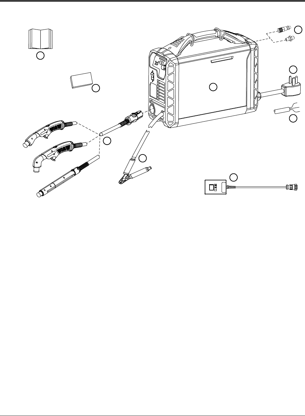
System contents
You can order additional consumables and accessories from any
Hypertherm distributor. See Replacement Parts and Accessories on
page 171.
1
2
3
5
6
7
9
4
8
1 Documentation:
•Operator Manual
•Quick Setup Card
• Registration card
• Safety and Compliance Manual
2 Starter consumable kit
3 15° or 75° hand torch with lead or
machine torch with lead
4 Work clamp with work lead
5 Remote-start pendant (optional – mechanized
configurations only)
6 CE/CCC and 480 V CSA models: power
cord with no power plug (some models ship
without a power cord)
7 CSA 200 V – 240 V models: power cord with
50 A, 250 V plug (NEMA 6-50P)
8 Region-specific gas inlet fitting (may not be
preinstalled)
9 Plasma power supply

Installation and Setup
1
Powermax45 XP Operator Manual 809240 23
What to do if components are missing or damaged
Claims for damage during shipment
File a claim with the carrier if your system was damaged during shipment.
Obtain the system’s model number and serial number, located on the bottom of the
plasma power supply.
Obtain a copy of the bill of lading from Hypertherm.
Claims for missing or damaged merchandise
Contact your Hypertherm distributor if any component is missing or damaged.
If you need additional assistance, call the nearest Hypertherm office listed in the front of this manual.
Hypertherm plasma power supply ratings
Rated open-circuit voltage (U
0
) 200 – 240 V, CSA/CE/CCC
400 V, CE/CCC
480 V, CSA
275 VDC
265 VDC
275 VDC
Output characteristic* Drooping
Rated output current (I
2
) 10A–45A
Rated output voltage (U
2
) 145 VDC
Duty cycle at 40°C (104°F)
†
50% at 45 A (I
2
) / 145 VDC (U
2
)
60% at 41 A (I
2
) / 145 VDC (U
2
)
100% at 32 A (I
2
) / 145 VDC (U
2
)
Operating temperature -10°C – 40°C (14°F – 104°F)
Storage temperature -25°C – 55° C (-13°F – 131°F)
Power factor 200 – 240 V, 1-phase, CSA/CE/CCC
400 V, 3-phase, CE/CCC
480 V, 3-phase, CSA
0.99
0.94
0.93
Idle state power consumption
(CE systems)
230 V
400 V
25 W
23 W
Power source efficiency at rated
maximum output power
(CE systems)
230 V
400 V
90.3%
89.9%
R
sce
– Short Circuit Ratio
(CE systems only)
U
1
– Volts AC rms, 3-phase
400 V CE
R
sce
250
EMC emissions classification
CISPR 11 (CE models only)
‡
Class A

Installation and Setup
1
24 809240 Operator Manual Powermax45 XP
Cutting specifications
Recommended cut capacity – handheld
Input voltage (U
1
) / Input current (I
1
)
at rated output (U
2MAX
I
2MAX
)
(See Voltage configurations on
page 31.)
200 – 240 V CSA
230 V CE/CCC**,
††
400 V CE/CCC**,
‡‡
480 V CSA
200 – 240 V, 1-phase, 50/60 Hz, 39 – 32 A
230 V, 1-phase, 50/60 Hz, 33 A
400 V, 3-phase, 50/60 Hz, 11 A
480 V, 3-phase, 50/60 Hz, 9.4 A
Gas type Air Nitrogen (N
2
) F5*** Argon
†††
Gas quality Clean, dry,
oil-free per
ISO 8573-1
Class 1.2.2
99.95% pure
Clean, dry,
oil-free
99.98% pure
(F5 = 95%
nitrogen [N
2
], 5%
hydrogen [H])
99.99% pure
Clean, dry,
oil-free
Recommended gas inlet
flow rate/pressure
Cutting 188.8 L/min at 5.9 bar (400 scfh at 85 psi)
Maximum control gouging 165.2 L/min at 4.1 bar (350 scfh at 60 psi)
Precision gouging, marking 165.2 L/min at 3.8 bar (350 scfh at 55 psi)
* Defined as a plot of output voltage versus output current.
†
See the data plate on the bottom of the power supply for more information on duty cycle and for IEC ratings.
‡
WARNING: This Class A equipment is not intended for use in residential locations where the electrical power is
provided by the public low voltage supply system. There may be potential difficulties in delivering electromagnetic
compatibility in those locations, due to conducted as well as radiated disturbances.
** This product meets the technical requirements of IEC 61000-3-3 and is not subject to conditional connection.
††
Equipment complies with IEC 61000-3-12.
‡‡
Equipment complies with IEC 61000-3-12 provided that the short-circuit power S
sc
is greater than or equal to
1911 KVA at the interface point between the user’s supply and the public system. It is the responsibility of the
installer or user of the equipment to ensure, by consultation with the distribution network operator if necessary, that
the equipment is connected only to a supply with a short-circuit power S
sc
greater than or equal to 1911 KVA.
*** F5 recommended only for cutting stainless steel. See page 117.
†††
Argon recommended only for marking applications at 10 – 25 A. See page 119.
Cut speed Material thickness
500 mm/min (20 inches per minute [in/min])* 16 mm (5/8 inch)
250 mm/min (10 in/min)* 22 mm (7/8 inch)
125 mm/min (5 in/min)* – severance capacity 29 mm (1-1/8 inch)
* Cut capacity speeds are not necessarily maximum speeds. They are the speeds that must be achieved to
be rated at that thickness.

Installation and Setup
1
Powermax45 XP Operator Manual 809240 25
Pierce capacity
Maximum cut speeds (mild steel)
Maximum cut speeds are the results of Hypertherm’s laboratory testing. Actual cutting speeds may
vary based on different cutting applications.
Gouge capacity
Torch type Material thickness
Handheld 12 mm (1/2 inch)
Mechanized with a programmable torch height control 12 mm (1/2 inch)
Material thickness Cut speed
6 mm (1/4 inch) 2286 mm/min (90 in/min)
9mm (3/8inch) 1219 mm/min (48 in/min)
12 mm (1/2 inch) 762 mm/min (30 in/min)
16 mm (5/8 inch) 508 mm/min (20 in/min)
19 mm (3/4 inch) 330 mm/min (13 in/min)
25 mm (1 inch) 178 mm/min (7 in/min)
Process Metal type
Output
current
Metal removal rate
Maximum Control gouging (26 – 45 A) Mild steel 45 A 3.4 kg/hour (7.5 pounds/hour)
Precision gouging (10 – 25 A) Mild steel 10 A 0.2 kg/hour (0.5 pounds/hour)

Installation and Setup
1
26 809240 Operator Manual Powermax45 XP
Noise levels
This plasma system may exceed acceptable noise levels as defined by national and local codes.
Always wear proper ear protection when cutting or gouging. Any noise measurements taken
depend on the specific environment in which the system is used. Refer to Noise can damage
hearing in the Safety and Compliance Manual (80669C) included with your system.
In addition, you can find an Acoustical Noise Data Sheet for your system at
www.hypertherm.com
:
1. Click “Documents library” near the bottom of the page.
2. Select a product from the “Product type” menu in the “Search” section of the page.
3. Select “Regulatory” from the “All Categories” menu.
4. Select “Acoustical Noise Data Sheets” from the “All subcategories” menu.
Critical raw materials
Critical raw material Components that contain more than 1 gram
Antimony Torch leads
Borate All printed circuit boards
Magnesium Heatsinks, metal covers
Silicon metal Heatsinks, metal covers
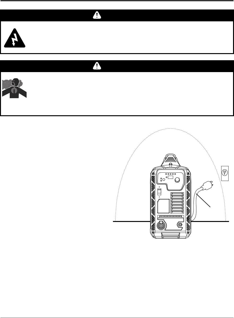
Installation and Setup
1
Powermax45 XP Operator Manual 809240 27
Position the plasma power supply
Do not use the system in rain or
snow.
Position the plasma power supply
near an appropriate power
receptacle. Its power cord is
approximately 3.0 m (10 feet).
Allow at least 0.25 m (10 inches)
of space around the power
supply for proper ventilation.
WARNING
CHANCE OF ELECTRIC SHOCK
Never cut under water or submerge the torch in water. Electric shock can cause
serious injury.
WARNING
TOXIC FUMES CAN CAUSE INJURY OR DEATH
Some metals, including stainless steel, may release toxic fumes when cut. Make sure
your work site has adequate ventilation to ensure that the air quality level meets all
local and national standards and regulations. Refer to the Safety and Compliance
Manual (80669C) for more information.
Clearance:
>0.25m (10inches)
3m (10feet)
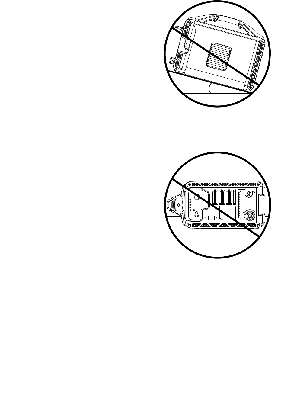
Installation and Setup
1
28 809240 Operator Manual Powermax45 XP
Place the power supply on a
stable, level surface before using.
It can tip over if set at an angle
greater than 10°.
Do not place the power supply
on its side. Doing so can block
the louvers on the side of the
cover and prevent proper air
circulation needed to cool
internal components.
>10°
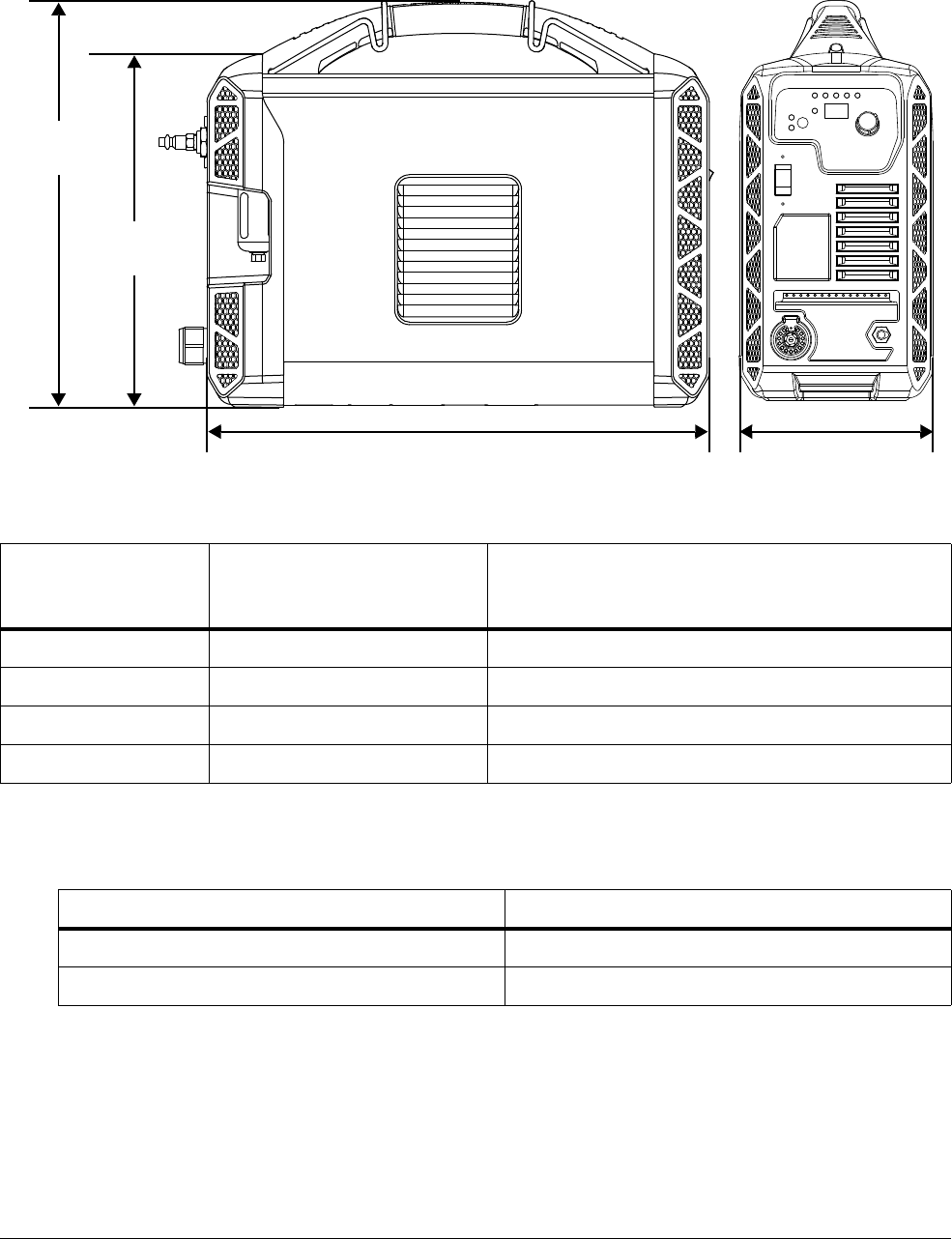
Installation and Setup
1
Powermax45 XP Operator Manual 809240 29
Power supply dimensions and weight
Work lead weights
For hand torch weights, see page 63. For machine torch weights,
seepage93.
Power supply with
power cord
Power supply (and power cord) with
6.1 m (20 foot) hand torch and
7.6 m (25 foot) work lead
200 – 240 V CSA 12 kg (26 pounds) 15 kg (33 pounds)
230V CE/CCC 12kg (27pounds) 15kg (33pounds)
400V CE/CCC 11kg (25pounds) 14kg (31pounds)
480V CSA 11kg (25pounds) 14kg (31pounds)
Work lead Weight
Work clamp with 7.6m (25foot) work lead 1.2kg (2.6pounds)
Work clamp with 15 m (50 foot) work lead 2.1 kg (4.7 pounds)
443 mm
(17.4 inches)
173 mm
(6.8 inches)
312 mm
(12.3 inches)
357 mm
14.1 inches)
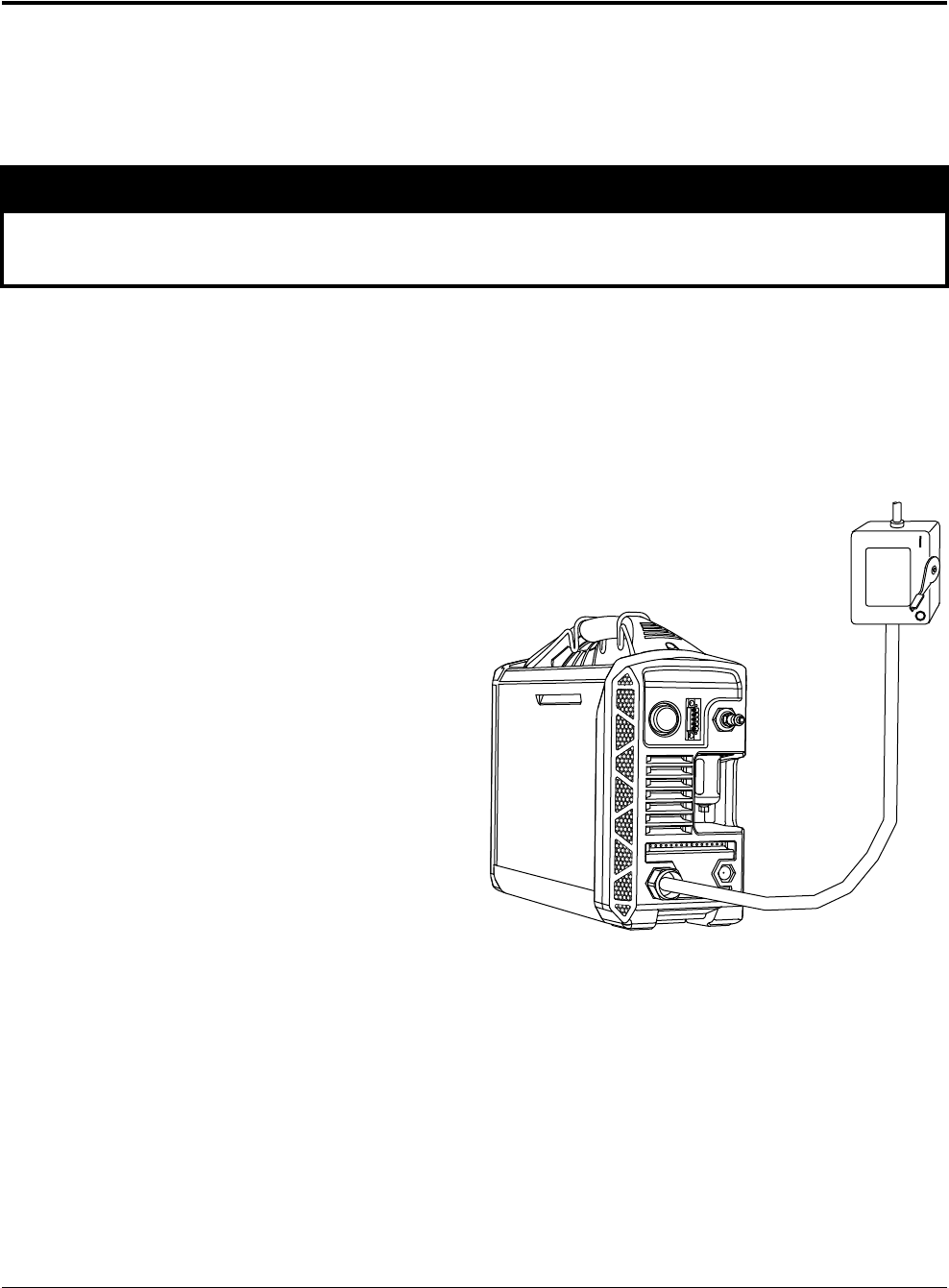
Installation and Setup
1
30 809240 Operator Manual Powermax45 XP
Connect to electrical power
Use the Hypertherm input current ratings to determine conductor sizes for power connection and
installation instructions. The Hypertherm ratings are designated HYP on the data plate on the
bottom of the power supply. Use the higher HYP input current value for installation purposes. See
page 184 for a sample data plate.
The maximum output voltage varies based on input voltage and the circuit’s amperage. Because the
current draw varies during startup, time-delay fuses are recommended. See Voltage configurations
on page 31. Time-delay fuses can withstand currents up to 10 times the rated value for short
periods of time.
Install a line-disconnect switch
Use a line-disconnect switch for
each plasma power supply to
allow the operator to turn off the
incoming power quickly in an
emergency.
Place the switch so that it is
easily accessible to the operator.
Installation must be performed by
a licensed electrician according
to national and local codes.
The interrupt level of the switch
must equal or exceed the
continuous rating of the
fuses/breakers.
The switch should also:
Isolate the electrical
equipment and disconnect all
live conductors from the
incoming supply voltage when in the OFF position.
Have one OFF and one ON position that are clearly marked with O (OFF) and I (ON).
Have an external operating handle that can be locked in the OFF position.
Contain a power-operated mechanism that serves as an emergency stop.
Have appropriate slow-blow fuses installed. See Voltage configurations on page 31 for
recommended fuse/breaker sizes.
NOTICE
Protect the circuit with appropriately sized time-delay fuses and a line-disconnect switch.

Installation and Setup
1
Powermax45 XP Operator Manual 809240 31
Requirements for grounding
To aid personal safety, proper operation, and to reduce electromagnetic interference
(EMI), the power supply must be properly grounded.
The power supply must be grounded through the power cord according to
national and local electrical codes.
Three-phase service must be of the 4-wire type with a green or green/yellow wire for
protective earth ground and must comply with national and local requirements.
Refer to the Safety and Compliance Manual (80669C) included with your system for more
information on grounding.
The system’s rated output (cutting power)
A plasma system’s cutting power is determined more by its wattage output than by its amperage
output. The rated output for this system is:
10 A – 45 A maximum output current
145 VDC maximum rated output voltage
6.5 kW cutting power
To determine the cutting power in watts (W), multiply the maximum output amperage (A) by the
maximum rated output voltage (VDC):
45 A × 145 VDC = 6,525 W (6.5 kW)
Voltage configurations
The system automatically adjusts for proper operation at the current input voltage without requiring
any switching or rewiring. However, you must:
Install a set of consumables in the torch. See Step 1 – Install consumables and activate
torch on page 48.
Set the output current using the adjustment knob on the front panel. See Step 6 – Set
mode and adjust output current (amperage) on page 53.
To operate the power supply at full output and 50% duty cycle as rated, you must size your electrical
service accordingly. The following tables show the maximum rated output for typical input voltages.
The output setting to use depends on the thickness of the metal and is limited by the input power to
the system.
The recommended fuse/breaker sizes account for spikes in input current
that occur when you stretch the plasma arc. Stretching the plasma arc is
common in some applications, such as gouging.

Installation and Setup
1
32 809240 Operator Manual Powermax45 XP
CSA/CE/CCC 200 V – 240 V (1-phase)
CSA 208 V (1-phase)
CCC 220 V (1-phase)
CE 230 V (1-phase)
Input voltage 200 V – 240 V
Input current at rated output (45 A x 145 V = 6.5 kW) 39 A – 32 A
Input current at arc stretch 44 A – 36 A
Recommended fuse/breaker size 50 A
Voltage tolerance 20% / -15%
Input voltage 208 V
Input current at rated output (45 A x 145 V = 6.5 kW) 37 A
Input current at arc stretch 43 A
Recommended fuse/breaker size 50 A
Voltage tolerance 20% / -15%
Input voltage 220 V
Input current at rated output (45 A x 145 V = 6.5 kW) 33 A
Input current at arc stretch 39 A
Recommended fuse/breaker size 50 A
Voltage tolerance 20% / -15%
Input voltage 230 V
Input current at rated output (45 A x 145 V = 6.5 kW) 33 A
Input current at arc stretch 37 A
Recommended fuse/breaker size 48 A
Voltage tolerance 20% / -15%

Installation and Setup
1
Powermax45 XP Operator Manual 809240 33
CCC 380 V (3-phase)
CE 400 V (3-phase)
CSA 480 V (3-phase)
Input voltage 380 V
Input current at rated output (45 A x 145 V = 6.5 kW) 12 A
Input current at arc stretch 20 – 15 A
Recommended fuse/breaker size 20 A
Voltage tolerance 20% / -10%
Input voltage 400 V
Input current at rated output (45 A x 145 V = 6.5 kW) 11 A
Input current at arc stretch 20 – 15 A
Recommended fuse/breaker size 20 A
Voltage tolerance +20% / -15%
Input voltage 480 V
Input current at rated output (45 A x 145 V = 6.5 kW) 9.4 A
Input current at arc stretch 17 – 12 A
Recommended fuse/breaker size 20 A
Voltage tolerance +20% / -10%

Installation and Setup
1
34 809240 Operator Manual Powermax45 XP
Decrease output current and arc stretch for lower rated electrical service
If you operate the power supply on an electrical service rated lower than what is recommended in
Voltage configurations on page 31, you may need to:
Turn down the cutting current (amperage setting). See Step 6 – Set mode and adjust
output current (amperage) on page 53.
Avoid stretching the plasma arc for prolonged periods. The more you stretch the plasma arc,
the more current the system draws and the more likely you are to overheat the system or trip
the circuit breaker.
Example: 230 V input on 20 A electrical service
If you use a 1-phase system with an input voltage of 230 V on a 20 A breaker, the recommended
output current is 19 A.
NOTICE
Do not operate this system on a 15 A or 16 A circuit breaker.
Input voltage 230 V
Input current at rated output (19 A x 145 V = 2.8 kW) 18 A
Input current at arc stretch 19 A
Voltage tolerance 20% / -15%

Installation and Setup
1
Powermax45 XP Operator Manual 809240 35
Prepare the power cord
CSA systems
1-phase (200 V – 240 V)
10 AWG 3-wire power cord
50 A, 250 V power plug
(NEMA 6-50P) included
To connect to a generator
that requires a 4-wire
connection, refer to Adapter
for 4-wire 1-phase
connections (CSA 1-phase
models only) on page 37.
3-phase (480 V)
14 AWG 4-wire power cord (some models ship without a power cord)
Power plug not included*
* An appropriate plug must be installed on the power cord by a licensed electrician according to national and
local codes.
CE/CCC systems
1-phase (200 V – 240 V)
6mm
2
3-wire H07RN-F power cord
Power plug not included*
3-phase (380 V / 400 V)
2.5 mm
2
4-wire H07RN-F power cord
Power plug not included*
* An appropriate plug must be installed on the power cord by a licensed electrician according to national and
local codes.
NEMA 6-50P (1-phase)
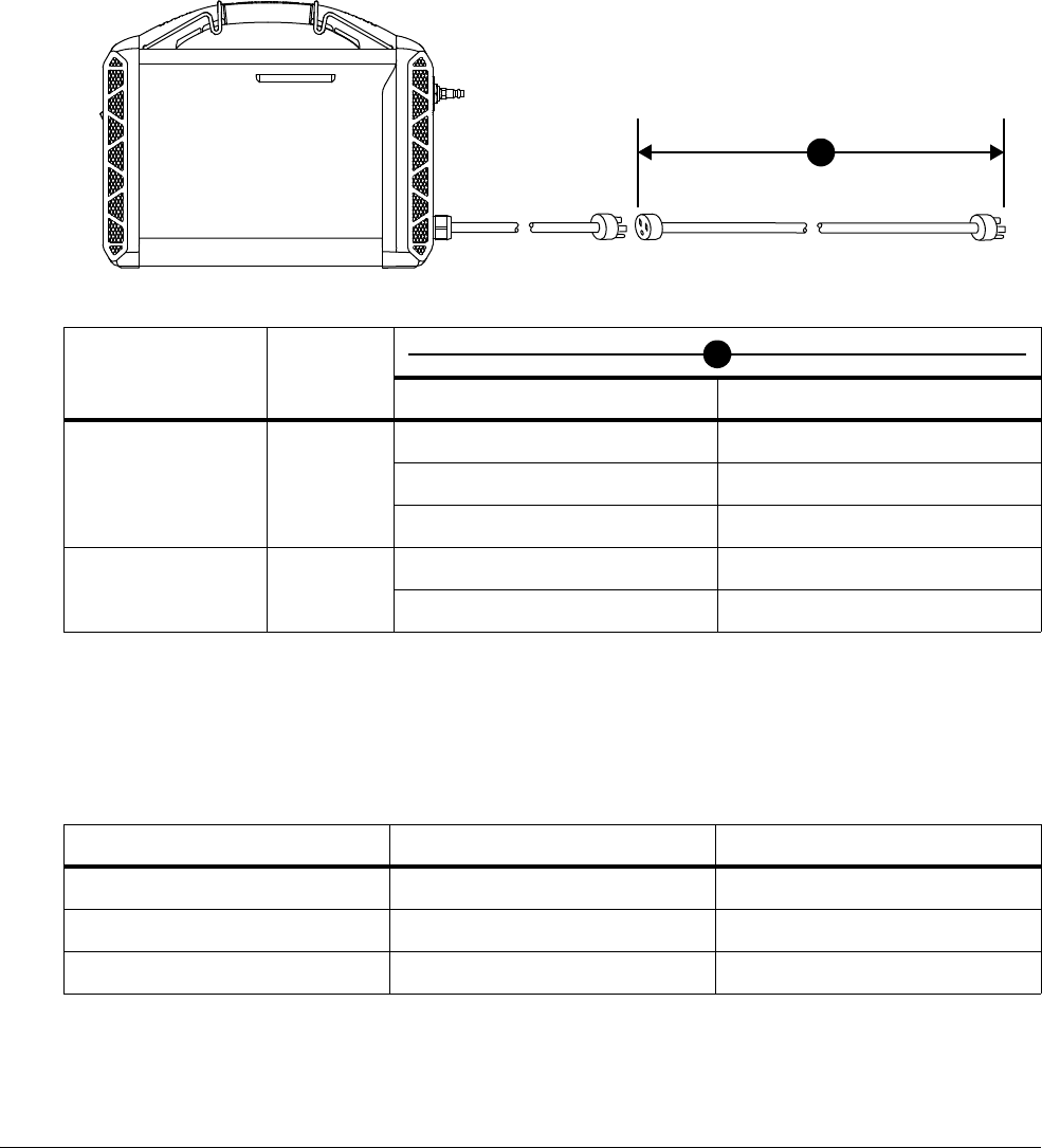
Installation and Setup
1
36 809240 Operator Manual Powermax45 XP
Extension cord recommendations
Use an extension cord that:
Is an appropriate wire gauge for the cord length and system voltage
Meets national and local codes
Extension cords can cause the machine to receive less input voltage than
the output of the circuit. This can limit the operation of your system.
Generator recommendations
Generators used with this system must meet the voltage requirements in the following table and in
Hypertherm plasma power supply ratings on page 23.
Adjust the cutting current (amperage) as needed based on the rating, age, and condition of
the generator.
Input voltage Phase
Cord Length Cord Gauge
200– 240VAC 1
up to 15 m (50 feet) 10 mm
2
(8 AWG)
15–30m (50–100feet) 16mm
2
(6 AWG)
30 – 45 m (100 – 150 feet) 25 mm
2
(4 AWG)
380 – 480 VAC 3
up to 15 m (50 feet) 4 mm
2
(12 AWG)
15 – 45 m (50 – 150 feet) 6 mm
2
(10 AWG)
1
1
Engine drive rating Plasma system output current Performance (arc stretch)
10 kW 45 A Full
8kW 45A Limited
6kW 30A Full
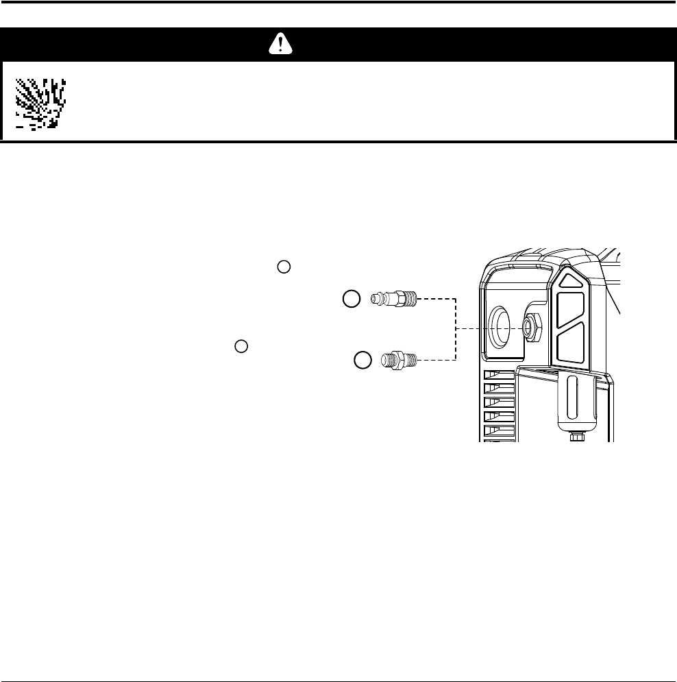
Installation and Setup
1
Powermax45 XP Operator Manual 809240 37
A 10 kW generator is recommended for cutting applications that require full arc stretch,
such as many gouging applications. It allows for the spikes in input current that occur when
you stretch the plasma arc.
If a fault occurs while using a generator, turn OFF (O) the system. Wait approximately
1 minute before you turn the system back ON (I).
Adapter for 4-wire 1-phase connections (CSA 1-phase models only)
Some generators require a 4-wire single phase connection (for example, NEMA 14-50R). In this
case, use an adapter to connect the power supply’s 3-wire power cord plug (NEMA 6-50P) to the
4-wire connector on the generator.
Connect the gas supply
All models: Use an inert gas hose with internal diameter of 9.5 mm (3/8 inch) or greater. Do
not use hoses with an internal diameter less than 9.5 mm (3/8 inch). Hoses that are
too small can cause issues with cut quality and cut performance.
CSA models: An industrial
interchange quick-disconnect
nipple with 1/4 NPT threads
comes with the system.
CE/CCC models: A British Pipe
Thread adapter G-1/4 BSPP
with 1/4 NPT threads comes
with the system.
The gas inlet fitting that comes
with the system may or may not
be preinstalled. To install the
fitting, screw it into place on the
back of the power supply.
CSA models: Tighten the 1/4 NPT fitting to 115 kg·cm (100 inch·pounds). The fitting
comes with thread sealant preapplied.
CE/CCC models: Tighten the G-1/4 BSPP adapter to 104 kg·cm (90 inch·pounds).
WARNING
The filter bowl in the power supply may explode if the gas pressure exceeds 9.3 bar
(135 psi).
1
2
1
2
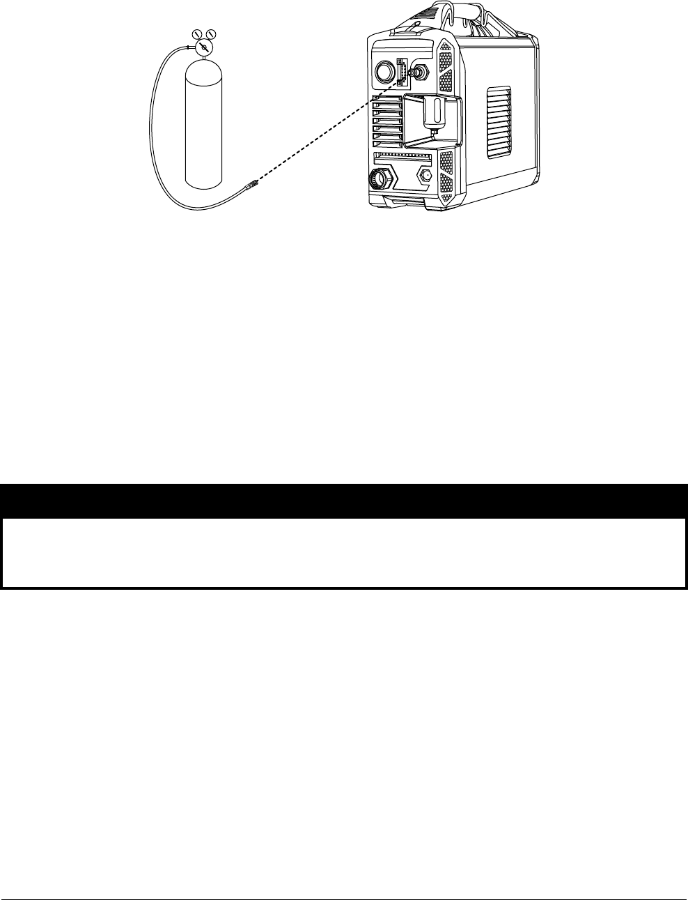
Installation and Setup
1
38 809240 Operator Manual Powermax45 XP
Gas supply source
Use shop-compressed gas or cylinder-compressed gas.
Use a high-pressure regulator on either type of gas supply. The regulator must be
capable of delivering gas to the air inlet on the power supply at the flow rate and
pressure specified above.
Use only clean, moisture-free gas.
Oil, water, vapor, and other contaminants in the gas supply can damage internal
components over time.
Poor gas supply quality results in:
Reduced cut quality and cut speeds
Reduced cut thickness capability
Reduced consumable life
NOTICE
Synthetic lubricants containing esters that are used in some air compressors will damage
polycarbonates used in the air filter bowl.
Recommended gas supply pressure: 5.5 – 6.9 bar (80 – 100 psi)
Maximum gas supply pressure: 9.3 bar (135 psi)
Recommended flow rate and pressure: 189 slpm at 5.9 bar (400 scfh at 85 psi)
Minimum flow rate: 165.2 slpm (350 scfh)
Maximum particle size: 0.1 micron at maximum concentration of 0.1 mg/m
3
*
Maximum water vapor dewpoint: -40°C (-40°F)
Maximum oil concentration: 0.1 mg/m
3
(for aerosol, liquid, and vapor)
* Per ISO8573-1:2010, Class 1.2.2. That is, it should have a maximum number of solid particulate per meter cubed
of 20,000 for particle sizes in the range of 0.1 – 0.5 microns, a maximum of 400 for particle sizes in the range of
0.5 – 1 microns, and a maximum of 10 for particle sizes in the range of 1 – 5 microns.
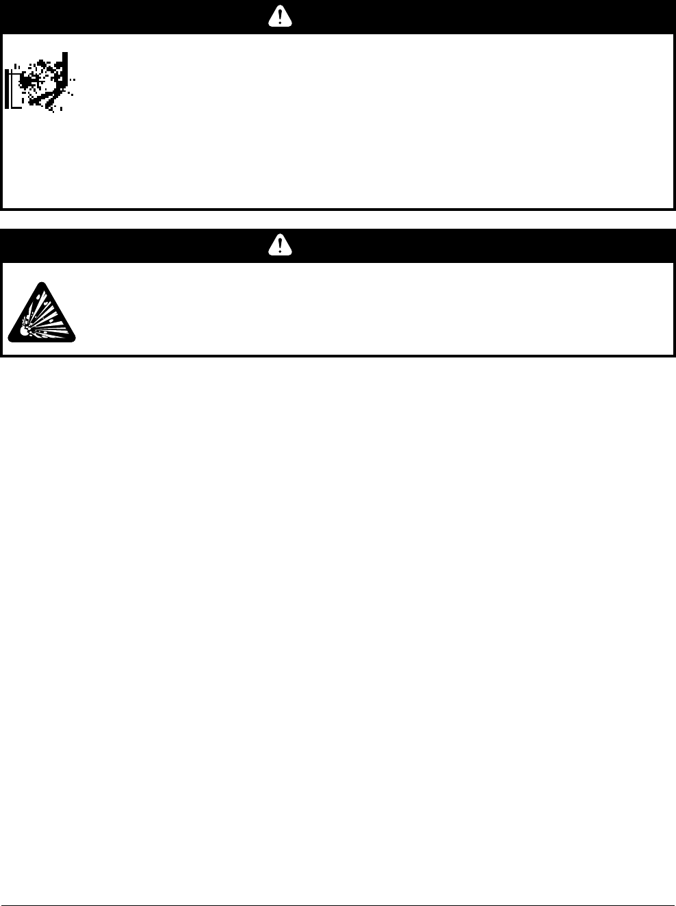
Installation and Setup
1
Powermax45 XP Operator Manual 809240 39
High-pressure gas cylinders
You can use the following gases to cut with this system. See Hypertherm plasma power supply
ratings on page 23 for requirements on gas quality.
Air
Nitrogen
F5 (stainless steel only – see page 117)
Argon (recommended for marking applications only – see page 120)
If you use high-pressure gas cylinders as the gas supply:
Refer to the manufacturer’s specifications for installation and maintenance procedures of
high-pressure regulators.
Make sure the cylinder valves are clean and free of oil, grease, and other contaminants.
Open each cylinder valve just long enough to blow out any dust that may be present.
Make sure the cylinder is equipped with an adjustable high-pressure regulator that is
capable of:
Gas outlet pressures up to 6.9 bar (100 psi). Never exceed the maximum gas
pressure of 9.3 bar (135 psi).
Gas flow rates of 235.9 L/min (500 scfh).
Connect the supply hose securely to the cylinder.
WARNING
GAS CYLINDERS CAN EXPLODE IF DAMAGED
Gas cylinders contain gas under high pressure. If damaged, a cylinder can explode.
For high pressure regulators, adhere to the manufacturer’s guidelines for safe
installation, operation, and maintenance.
Before plasma cutting with compressed gas, read the safety instructions in the
Safety and Compliance Manual (80669C). Failure to follow safety instructions can
result in personal injury or in damage to equipment.
WARNING
EXPLOSION HAZARD – CUTTING WITH FUEL GASES
Do not use combustible fuel gases or oxidizing gases with Powermax systems.
These gases can result in explosive conditions during plasma cutting operations.
Installation and Setup
1
40 809240 Operator Manual Powermax45 XP
Gas flow rates
Refer to the cut charts starting on page 129 for flow rates specific to each cutting process
specified (based on the type of metal, the type of gas, and the output current).
Minimum inlet pressure (while gas is flowing)
The following pressure specifications apply for air, nitrogen, F5, and argon. Never exceed an inlet
gas supply pressure of 9.3 bar (135 psi).
You may need to adjust these pressures based on the equipment and conditions specific to your
environment. For example, additional gas filtration installed between the gas supply and the plasma
power supply may increase the required minimum inlet pressure. Consult the filter manufacturer.
Cutting
Process Gas flow rate
Cutting 188.8 slpm (400 scfh) at a minimum 5.9 bar (85 psi)
Maximum control gouging
(26 – 45 A)
165.2 slpm (350 scfh) at a minimum 4.1 bar (60 psi)
Precision gouging / marking
(10 – 25 A)
165.2 slpm (350 scfh) at a minimum 3.8 bar (55 psi)
WARNING
The filter bowl in the power supply may explode if the gas pressure exceeds 9.3 bar
(135 psi).
Torch lead length – hand torches Minimum inlet pressure
6.1m (20feet) 5.5bar (80psi)
15 m (50 feet) 5.9bar (80psi)
Torch lead length – machine torches Minimum inlet pressure
7.6m(25feet) 5.5bar (80psi)
11 m (35 feet) 5.5bar (80psi)
15 m (50 feet) 5.9 bar (85 psi)

Installation and Setup
1
Powermax45 XP Operator Manual 809240 41
Maximum control gouging (26 – 45 A)
Precision gouging / Marking (10 – 25 A)
Torch lead length – hand torches Minimum inlet pressure
6.1m (20feet) 3.8bar (55psi)
15 m (50 feet) 4.1bar (60psi)
Torch lead length – machine torches Minimum inlet pressure
7.6m(25feet) 3.8bar (55psi)
11 m (35 feet) 3.8bar (55psi)
15 m (50 feet) 4.1 bar (60 psi)
Torch lead length – hand torches Minimum inlet pressure
6.1m (20feet) 3.5bar (50psi)
15 m (50 feet) 3.8bar (55psi)
Torch lead length – machine torches Minimum inlet pressure
7.6m(25feet) 3.5bar (50psi)
11 m (35 feet) 3.5bar (50psi)
15 m (50 feet) 3.8 bar (55 psi)
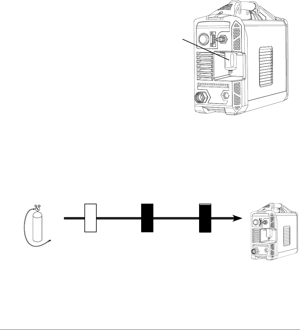
Installation and Setup
1
42 809240 Operator Manual Powermax45 XP
Additional gas filtration
It is extremely important to maintain a clean, dry gas line in order to:
Prevent oil, water, dirt, and other contaminants from damaging internal components.
Achieve optimal cut quality and consumable life.
Dirty, oily air is the root cause of many common problems that occur in Powermax systems, and in
some instances it can void the warranty on the power supply and on the torch. See the gas quality
recommendations in the ratings table on page 23.
The power supply contains a
built-in air filter. Regularly check
the filter element inside the air
filter bowl and replace as
needed. See Replace the air filter
bowl and filter element on
page 167.
The built-in air filter should not
take the place of adequate
external filtration. If you work in an
environment that is extremely
warm and humid, or if work site
conditions introduce oil, vapors,
or other contaminants into the
gas line, install an external
filtration system that cleans the
gas supply before it enters the plasma power supply.
A 3-stage coalescing filtration system is recommended. A 3-stage filtering system works as follows
to clean contaminants from the gas supply.
Install the filtering system between the gas supply and the power supply. Additional gas filtration
may require higher pressure from the source.
Air filter bowl
Water and particle
filter
Oil filter Oil vapor filter
Gas supply
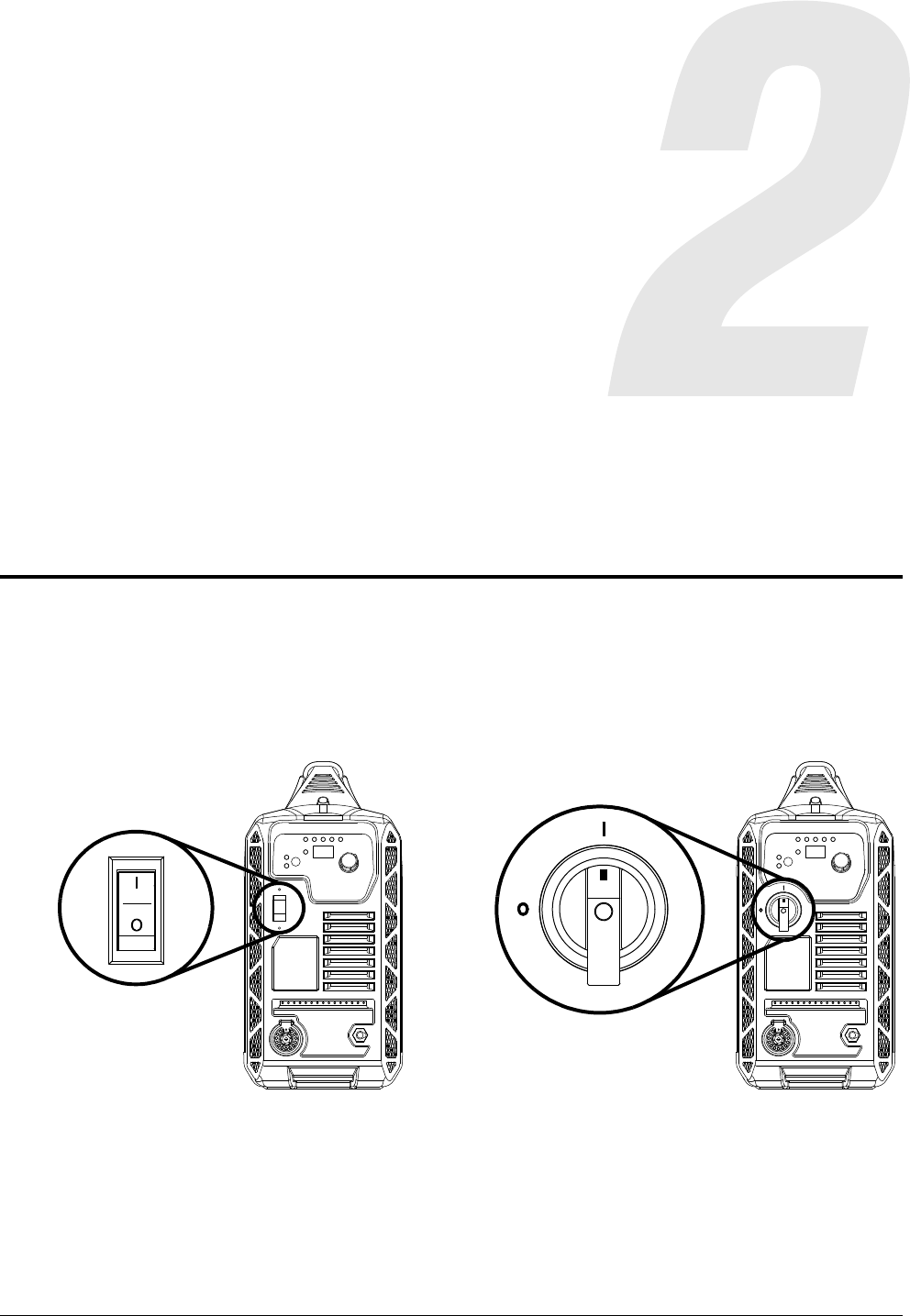
Powermax45 XP Operator Manual 809240 43
Operation
Controls and indicators
ON (I)/OFF(O) power switch
The power switch is located on the front panel.
200 – 240 V 400 V, 480 V
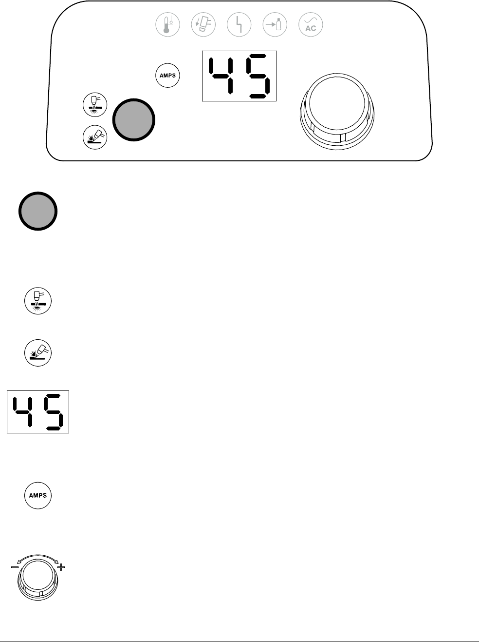
Operation
2
44 809240 Operator Manual Powermax45 XP
Cutting controls
Mode button – Press this button to toggle between cut mode and gouge/marking
mode. The system automatically adjusts the gas pressure based on:
The mode selected
The torch connected to the power supply
The length of the torch lead
Cut Mode LED (green) – When illuminated, this LED indicates that the system is
ready to perform plasma cutting operations.
Gouge/Marking Mode LED (green) – When illuminated, this LED indicates that the
system is ready to perform plasma gouging or marking operations.
2-digit display – This display shows the output current (10 – 45 A) by default.
When certain system faults occur, this display shows a fault code. See Fault
LEDs and fault codes on page 151.
If you manually adjust the gas pressure, this display shows the gas pressure.
See Adjust the gas pressure manually on page 56.
AMPS LED (green) – When illuminated, this LED indicates that the 2-digit display
shows the cutting current (amperage).
When the 2-digit display shows other values, such as gas pressure or a fault
code, the AMPS LED is not illuminated.
Adjustment knob – Use this knob to set the cutting current between 10 A and 45 A
in 1-unit increments.
You can also use this knob to increase or decrease the gas pressure. See Adjust
the gas pressure manually on page 56.
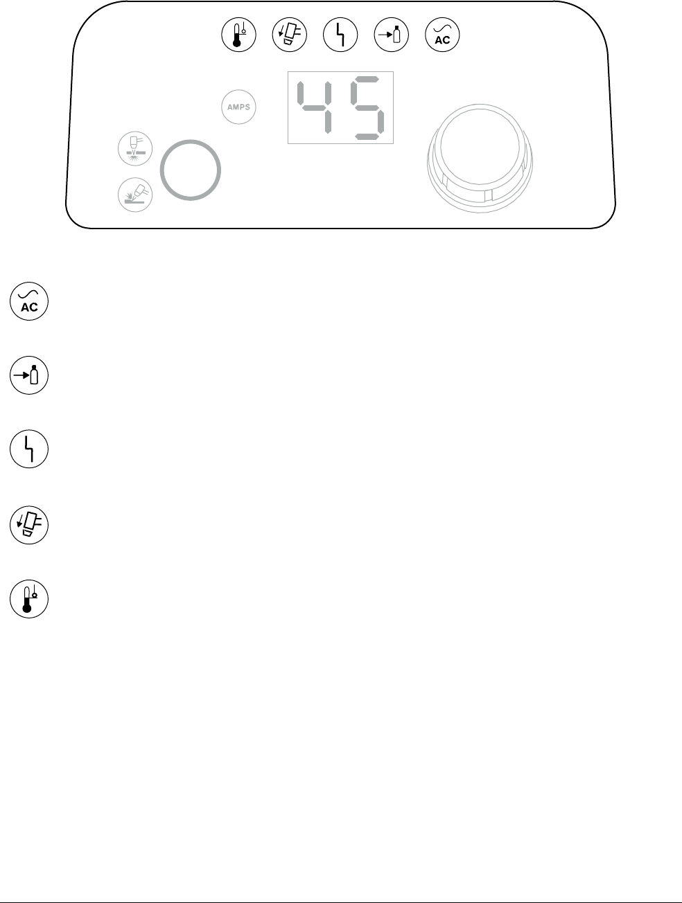
Operation
2
Powermax45 XP Operator Manual 809240 45
Indicator LEDs
Some fault conditions cause multiple LEDs to illuminate or blink at the
same time. For information on what these fault conditions are and how to
clear them, see Fault LEDs and fault codes on page 151.
Power ON LED (green) – When illuminated, this LED indicates that the power switch is set to
ON (I) and the system is ready to cut.
Gas Pressure LED (yellow) – When illuminated, this fault LED indicates that the inlet gas
pressure is too low or that there is no inlet gas connection.
System Fault LED (yellow) – When illuminated, this fault LED indicates that there is a fault
with the power supply. In many instances, when this LED illuminates, a fault code also
flashes on the 2-digit display. See Fault LEDs and fault codes on page 151.
Torch Cap LED (yellow) – When illuminated, this fault LED indicates that the consumables
are loose, improperly installed, or missing.
Temperature LED (yellow) – When illuminated, this fault LED indicates that the system’s
temperature is outside the acceptable operating range.
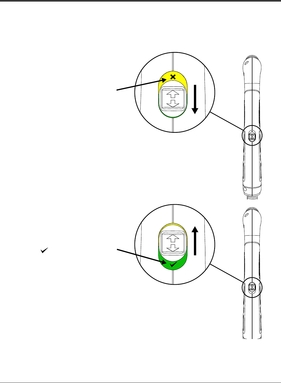
Operation
2
46 809240 Operator Manual Powermax45 XP
Disable the torch
The Duramax Lock torches include a switch that enables you to lock the torch. This torch-disable
switch prevents the torch from firing accidentally even when the power supply is ON. Use this
switch to lock the torch when it is not in use, when you need to change the consumables, or when
you need to move the power supply or torch while the system is powered ON.
Torch LOCK position:
The torch-disable switch is
in the backward position,
closer to the torch lead.
The yellow label with the
“X” indicates the torch is not
ready to fire.
Point the torch away from
yourself and others, and pull
the trigger to make sure it
does not fire.
Change the consumables (if
needed).
Torch “ready to fire” position:
The torch-disable switch is
in the forward position,
closer to the torch head.
The green label with the
“ ” indicates the torch is
ready to fire.
Do NOT change the
consumables.
To change the
consumables without
danger of the torch firing
accidentally, lock the
torch or turn OFF the
power supply.
The first time you pull
the torch trigger after you set the torch to the “ready to fire” position, the
torch emits multiple puffs of air in quick succession. This warns you that
the torch is active and will fire an arc the next time the trigger is pulled.
Seepage47.
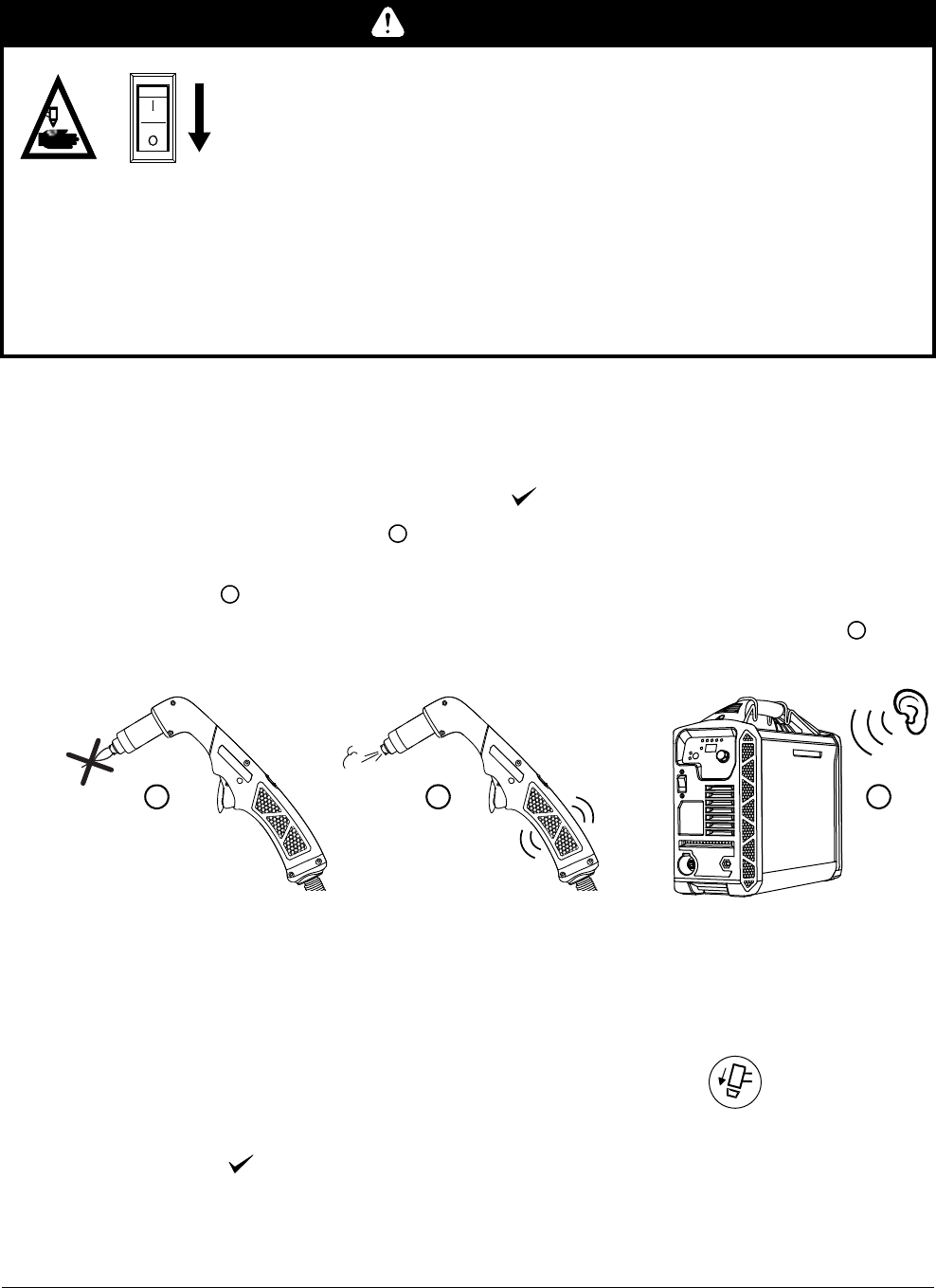
Operation
2
Powermax45 XP Operator Manual 809240 47
Warning puffs of air
The first time you try to fire the torch after moving the torch-disable switch to the yellow lock (X)
position and then back to the green “ready to fire” ( ) position:
The plasma arc does not fire.
The torch emits multiple puffs of air in quick succession. The torch vibrates slightly with each
puff of air.
The power supply makes an audible pressure-release sound with each puff of air.
This feedback serves as a warning. It does not indicate a fault condition. It alerts you that the torch is
activated and will produce a plasma arc the next time the torch is fired.
The Torch Cap LED on the front panel illuminates when you
remove the consumables or set the torch-disable switch to the
yellow lock (X) position while the plasma power supply is still
ON. The LED extinguishes after you install the consumables
and set the torch-disable switch to the green “ready to
fire” ( ) position.
WARNING
INSTANT-ON TORCHES – PLASMA ARC CAN CAUSE INJURY, BURNS
The plasma arc ignites immediately when you pull the torch trigger.
Before changing consumables, one of the following actions must be
taken. Whenever possible, complete the first action.
Turn OFF (O) the plasma power supply.
OR
Move the torch-disable switch to the yellow lock (X) position
(closest to the torch lead). Pull the trigger to make sure the
torch does not fire a plasma arc.
1
2
1 2
3
3
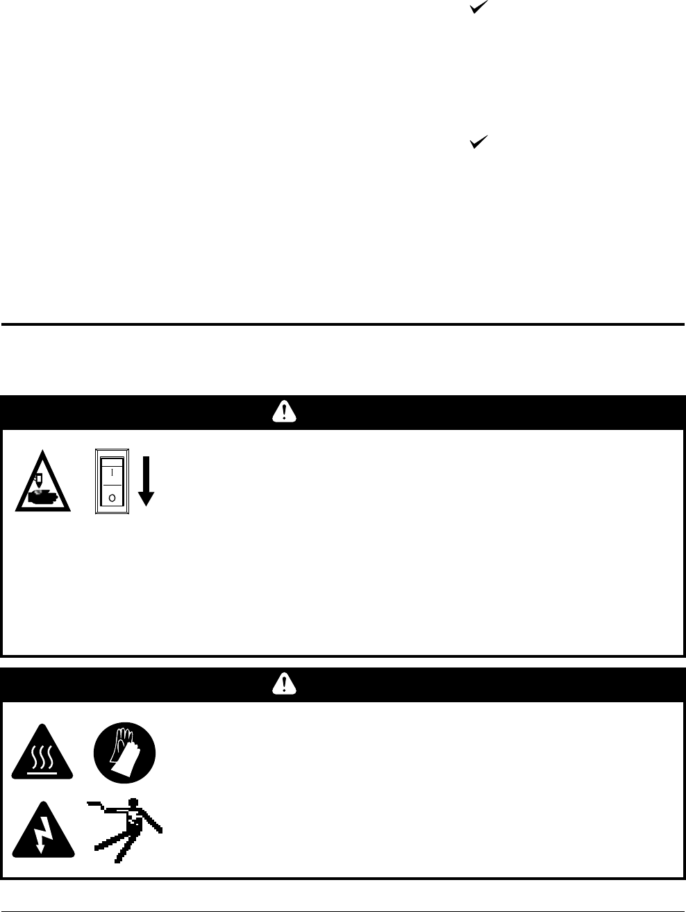
Operation
2
48 809240 Operator Manual Powermax45 XP
For hand torches
After moving the torch-disable switch to the green “ready to fire” ( ) position:
a. Pull the torch trigger 1 time to get the warning puffs of air.
b. Pull the torch trigger again to fire a plasma arc.
For machine torches
After moving the torch-disable switch to the green “ready to fire” ( ) position:
a. Run a START/STOP command from the CNC to get the warning puffs of air.
If this feature is integrated into your CNC, there may be other steps to
follow that are specific to the CNC.
b. Start the torch again to fire a plasma arc.
Operate the plasma system
Step 1 – Install consumables and activate torch
WARNING
INSTANT-ON TORCHES – PLASMA ARC CAN CAUSE INJURY, BURNS
The plasma arc ignites immediately when you pull the torch trigger.
Before changing consumables, one of the following actions must be
taken. Whenever possible, complete the first action.
Turn OFF (O) the plasma power supply.
OR
Move the torch-disable switch to the yellow lock (X) position
(closest to the torch lead). Pull the trigger to make sure the
torch does not fire a plasma arc.
WARNING
RISK OF BURNS AND ELECTRIC SHOCK – WEAR INSULATED GLOVES
Always wear insulated gloves when changing the consumables. The
consumables get very hot during cutting and can cause severe burns.
Touching the consumables can also result in electric shock if the power
supply in ON and the torch-disable switch is not in the yellow lock (X)
position.
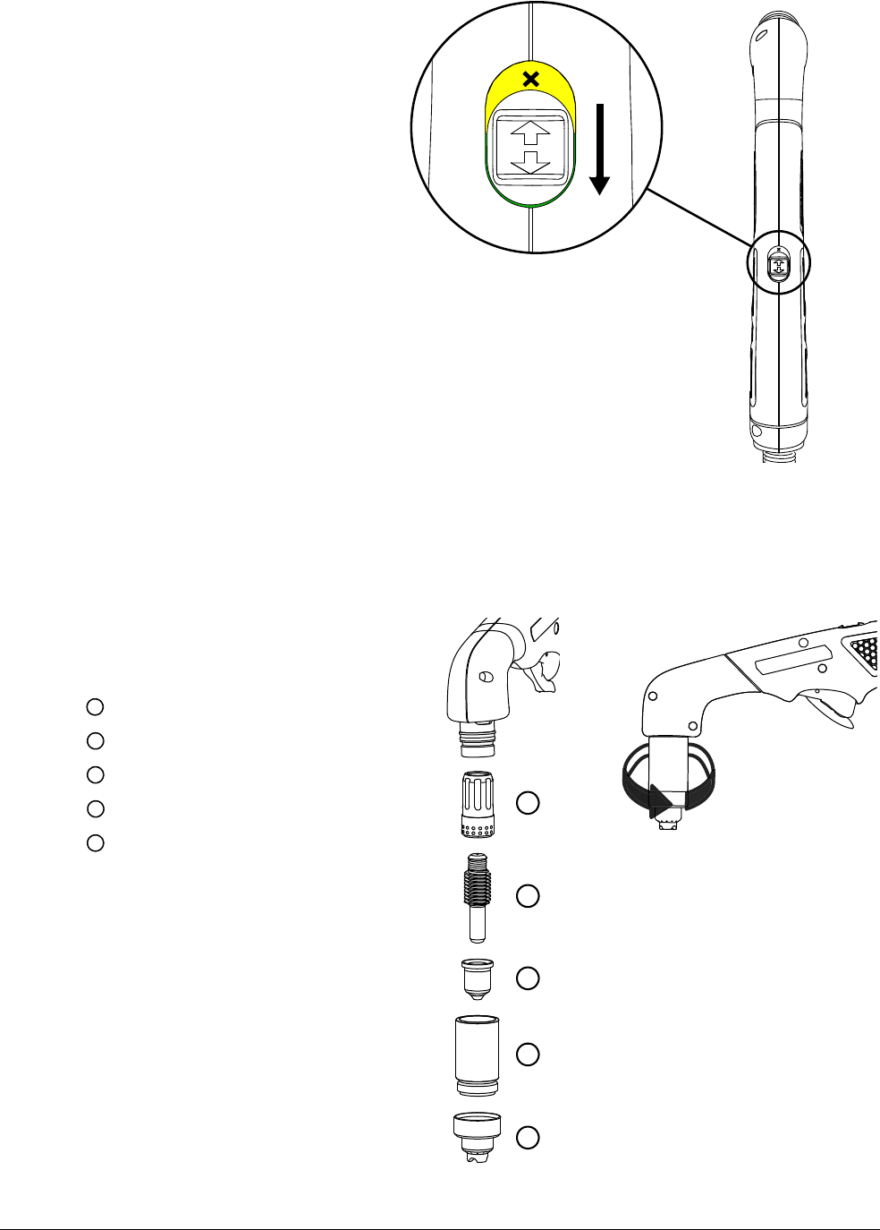
Operation
2
Powermax45 XP Operator Manual 809240 49
1. Turn O F F (O) the power
switch on the power supply,
or move the torch-disable
switch on the torch to the
yellow lock (X) position.
2. Point the torch away from
yourself and others, and pull
the trigger to make sure it
does not fire.
3. Choose the correct
consumables for your cutting,
gouging, or marking
application.
Cutting and piercing
with a hand torch:
See Choose the
consumables on
page 63.
Cutting and piercing
with a machine torch: See Choose the consumables on page 111.
Gouging: See Gouging processes on page 75.
Marking: See Marking consumables (10 – 25 A) on page 119.
4. Install a complete set of
consumables in the hand torch or
machine torch as shown:
Swirl ring
Electrode
Nozzle
Retaining cap
Shield (or deflector)
Consumables are not
preinstalled on new torches.
Remove the vinyl cap from
the torch before installing the
consumables.
1
2
3
5
4
Tighten to finger tight.
Do not over-tighten.
1
2
3
4
5
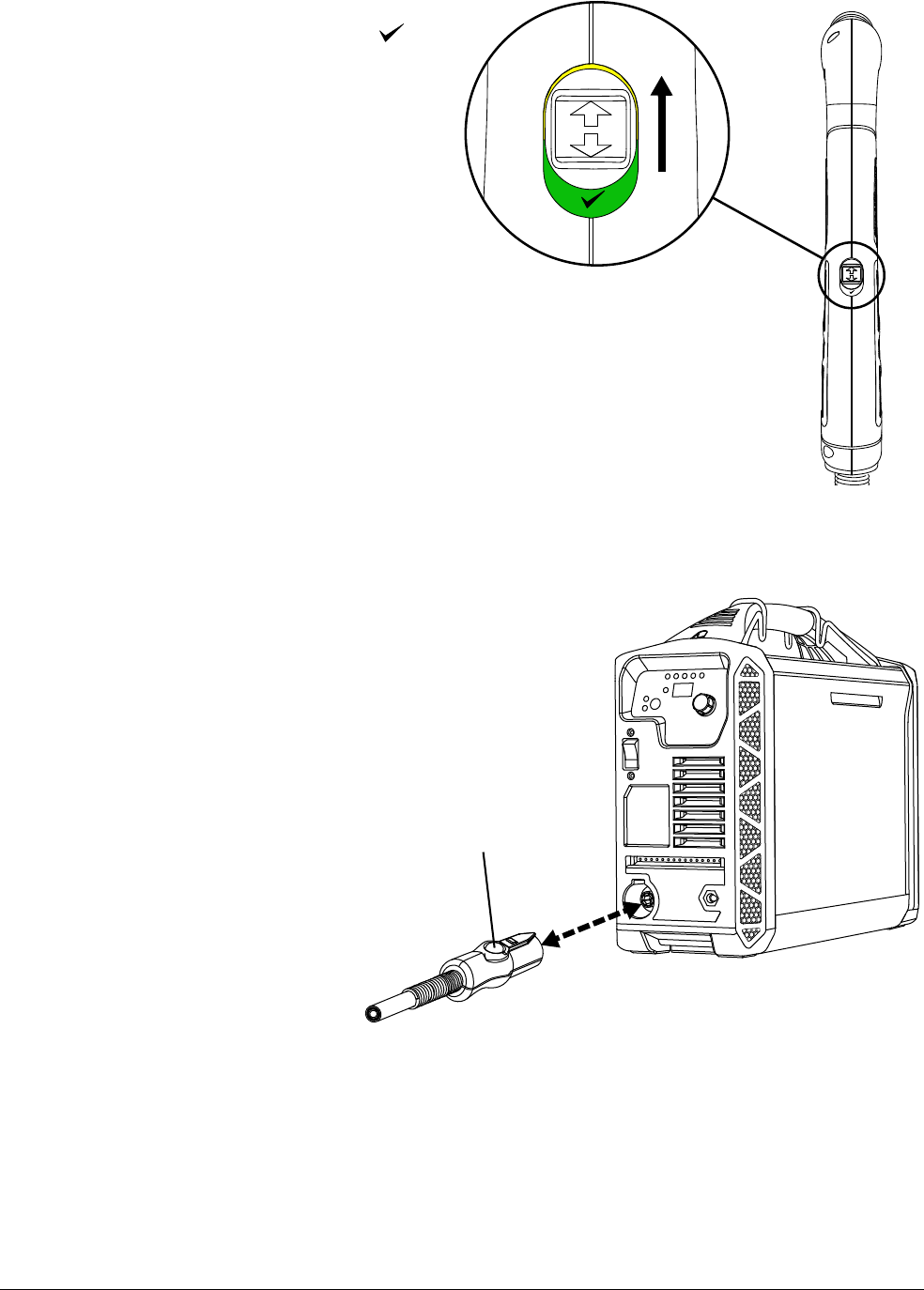
Operation
2
50 809240 Operator Manual Powermax45 XP
5. Move the torch-disable switch on the
torch to the green “ready to fire” ( )
position.
Step 2 – Connect torch lead
Turn OF F (O) the power
supply before you
connect or disconnect a
torch.
To connect a hand torch
or machine torch, push
the connector into the
receptacle on the front of
the power supply.
To disconnect the torch,
press the red button on
the connector and pull
the connector out of the
receptacle.
Red button
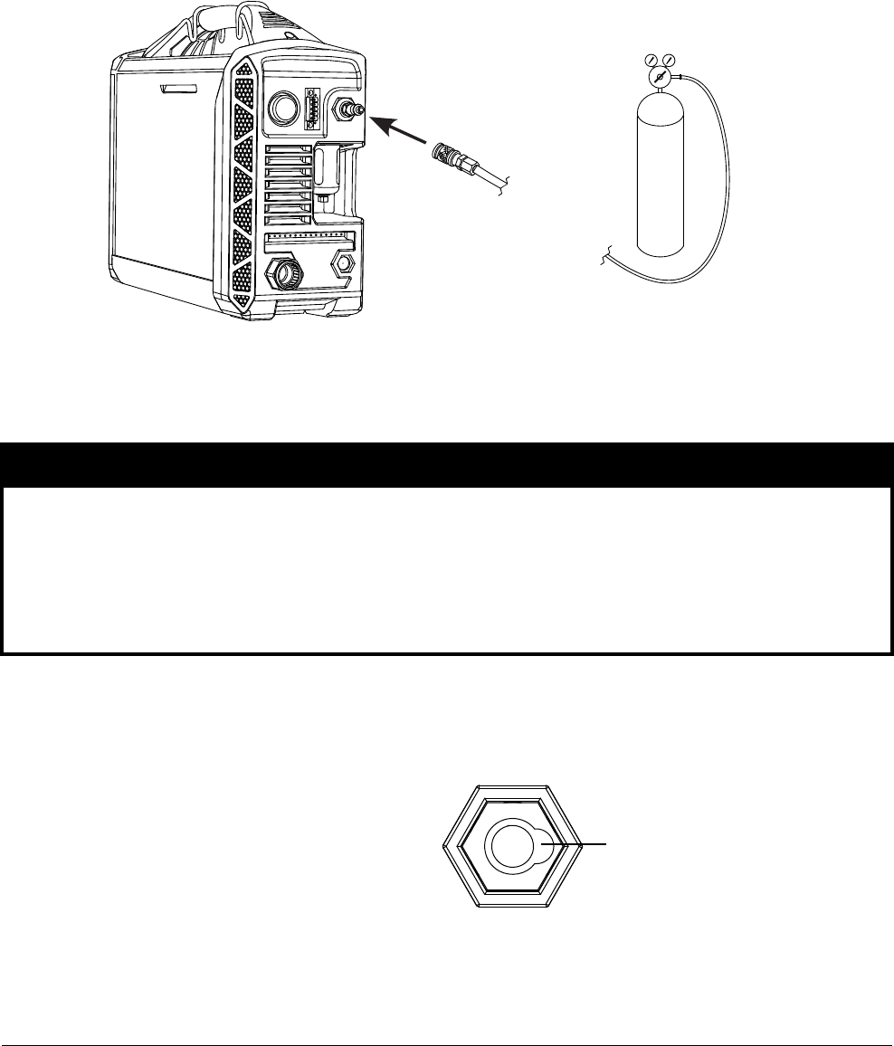
Operation
2
Powermax45 XP Operator Manual 809240 51
Step 3 – Connect gas supply
If needed, install the gas inlet fitting that came with the system onto the back of the power
supply. See page 37.
Connect the gas supply line to the fitting on the back of the power supply.
For gas supply requirements, see Gas supply source on page 38.
Step 4 – Connect work lead and work clamp
Work lead
1. Insert the work lead connector into
the receptacle on the front of the
power supply. Align the key on the
connector with the opening on the
right of the receptacle.
2. Push the work lead connector all the
way into the receptacle. Turn the
connector clockwise a 1/4 turn until
the connector is fully seated against
the stop.
NOTICE
Make sure you use a work lead that is appropriate for your power supply. Use a 45 A work lead
with the Powermax45 XP. The amperage is marked near the rubber boot of the work lead
connector.
To prevent overheating, check the work lead often to make sure it is fully seated in the
receptacle.
Keyed opening at right of work lead
receptacle
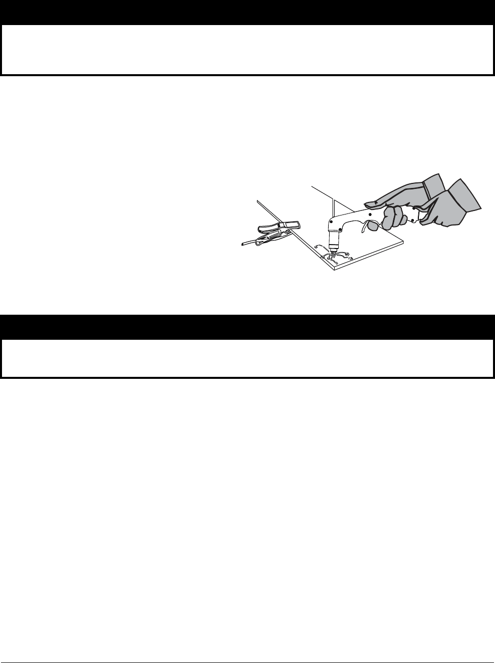
Operation
2
52 809240 Operator Manual Powermax45 XP
Work clamp
Hand cutting: The work clamp must be connected to the workpiece you are cutting.
Mechanized cutting: If you are using this system with a cutting table, you can connect the
work clamp directly to the table or to the workpiece you are cutting. See your table
manufacturer’s instructions.
Make sure the work clamp makes
good metal-to-metal contact with
the workpiece or cutting table.
Remove rust, dirt, paint, coatings,
and other debris so the work
clamp makes proper contact with
the workpiece or cutting table.
To achieve the best cut quality,
attach the work clamp as close
as possible to the area being cut.
NOTICE
Do not attach the work clamp under water. If the power supply is below the work clamp, water
can enter the power supply via the work lead and cause severe damage.
NOTICE
Do not attach the work clamp to the portion of the workpiece to be cut away.
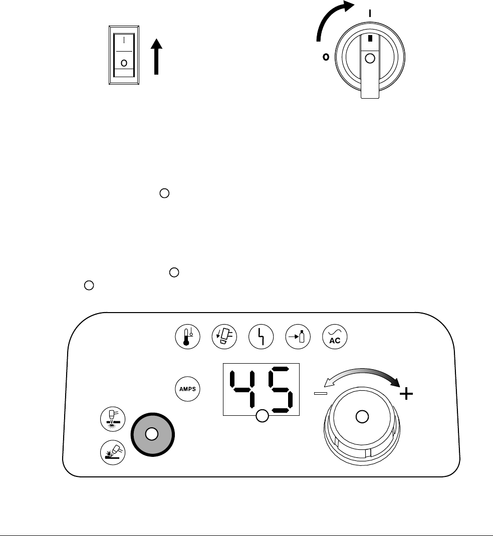
Operation
2
Powermax45 XP Operator Manual 809240 53
Step 5 – Connect electric power and turn ON the system
1. Plug in the power cord.
When you first receive your system, the power cord may not have a power plug installed.
For information on connecting the proper plug to the power cord, see Prepare the power
cord on page 35.
For more information on the system’s electrical requirements, see Connect to electrical
power on page 30.
2. Set the power switch to the ON (I) position.
Step 6 – Set mode and adjust output current (amperage)
1. Press the Mode button to toggle between Cut mode and Gouge/Marking mode.
The system’s Smart Sense™ technology automatically regulates the gas
pressure for optimum cutting according to the selected mode, the torch
type, and the length of the torch lead.
2. Turn the adjustment knob to set the output current to a maximum of 45 A. The 2-digit
display shows the output current in amperage.
200 – 240 V
400 V, 480 V
1
2
3
1
2
3
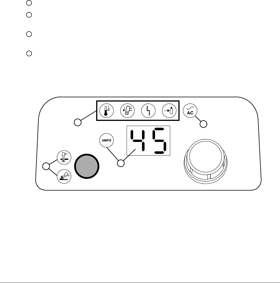
Operation
2
54 809240 Operator Manual Powermax45 XP
Cutting expanded metal
To cut expanded metal, use the consumables for shielded cutting that come with the system. The
system does not require a dedicated mode for cutting expanded metal.
Expanded metal has a slotted or mesh pattern. Cutting expanded metal
wears out consumables more quickly because it requires a continuous
pilot arc. A pilot arc occurs when the torch is fired but the plasma arc is
not in contact with the workpiece.
Step 7 – Check cut settings and indicator LEDs
Before you start to cut, make sure:
If any of the fault LEDs illuminate or blink, or if the power ON LED blinks, this indicates a
fault. Correct the fault condition before continuing. See Fault LEDs and fault codes on
page 151.
The green power ON LED on the front of the power supply is illuminated.
The correct mode LED is illuminated (cut or gouge/marking). Also make sure the
consumables installed on the torch match the selected mode.
The output current (amperage) displayed on the front panel is correct, and the AMPS LED
is illuminated.
None of the 4 fault LEDs are illuminated or blinking.
1
2
3
4
2
3
4
1
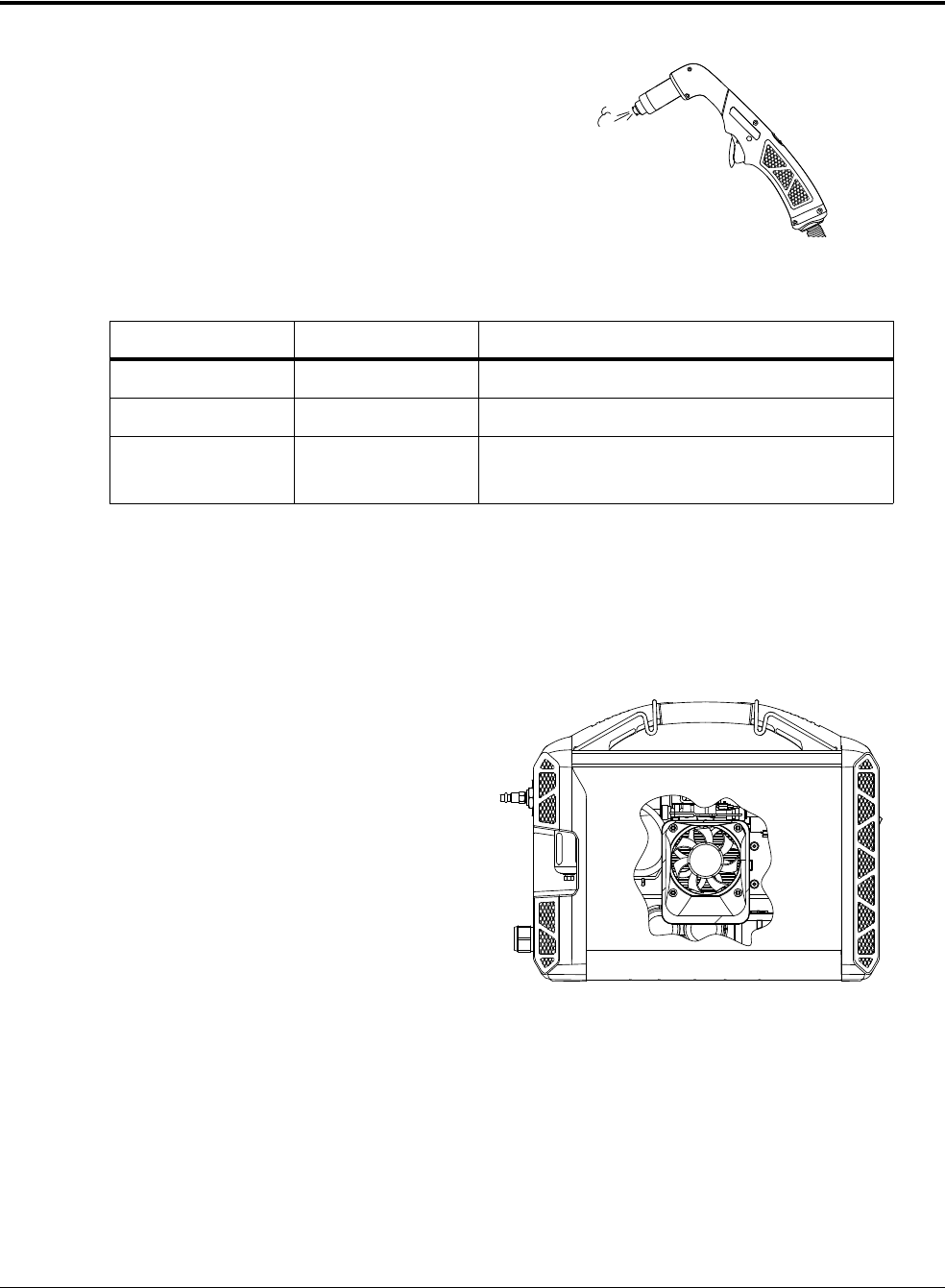
Operation
2
Powermax45 XP Operator Manual 809240 55
What to expect during and after cutting
Postflow – After you complete a cut and
release the torch trigger, air continues
to flow from the torch in order to cool
the consumables. This is referred to as
postflow.
The length of postflow depends on the
mode and the output current. Under
certain conditions, it also depends on
the gas supply.
Exception for argon: The system recognizes when argon is being used and reduces
postflow from 10 seconds to 3 seconds in order to minimize gas usage. To achieve 3-second
postflow, the system must be set to Gouge/Marking mode with the output current set
between 10 – 25 A. When the torch fires without transferring the pilot arc to the workpiece,
postflow is 10 seconds even when the supply gas is argon.
Fan activity – The cooling fan inside the
plasma power supply runs
intermittently during and after
cutting in order to cool internal
components.
Mode Output current Length of postflow
Cut 10–45A 20seconds
Gouge/marking 26 – 45 A 20 seconds
Gouge/marking 10 – 25 A 10 seconds for air (or nitrogen)
3 seconds for argon
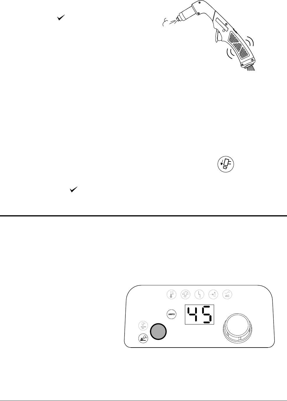
Operation
2
56 809240 Operator Manual Powermax45 XP
Warning puffs of air – When you set the
torch-disable switch to the “ready
to fire” ( ) position after the
torch has been locked, the torch
does not fire the first time you pull
the trigger. Instead, the torch emits
multiple puffs of air in quick
succession. With each puff of air,
the torch vibrates slightly, and the
power supply emits an audible
pressure-release sound. This
serves as a warning to alert you
that the torch is active and will fire
an arc the next time you pull the
trigger. Seepage47.
For the machine torch, run a START/STOP command from the CNC to
cause the torch to emit the puffs of air. On the next start signal, the torch
will fire an arc.
The Torch Cap LED on the front panel illuminates when you
remove the consumables or set the torch-disable switch to the
yellow lock (X) position while the plasma power supply is still
ON. The LED extinguishes after you install the consumables
and set the torch-disable switch to the green “ready to
fire” ( ) position.
Adjust the gas pressure manually
The power supply automatically regulates the gas pressure for you. However, you can adjust the gas
pressure manually if you need to for a specific application.
Overriding the system’s gas pressure setting should be done only by
experienced users who need to optimize the gas setting for a specific
cutting application.
1. Select the mode, and set the
output current. In this
example, we selected
gouge/marking mode and set
the output current to 45 A.
Set the mode and
output current first
because doing so
can reset the gas
pressure. See
page 58.
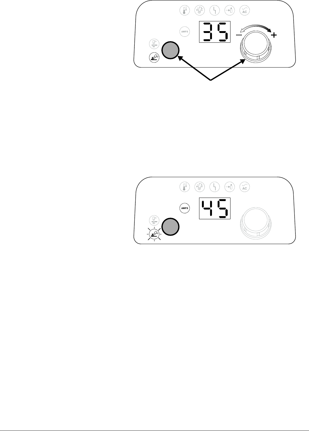
Operation
2
Powermax45 XP Operator Manual 809240 57
2. Press-and-hold the Mode
button with one hand. Turn
the adjustment knob to the
desired gas pressure with the
other hand. In this example,
we turned down the gas
pressure to 35 psi.
As you manually
adjust the gas
pressure, the AMPS
LED turns off, and the
2-digit display
changes from
amperage to gas
pressure, as follows:
CSA models: The gas pressure displays in psi by default.
CE/CCC models: The gas pressure displays in bar by default.
You can change the display values for gas pressure. See page 59.
3. Release the Mode button.
After you release the
Mode button, the
AMPS LED
illuminates again, and
the 2-digit display
changes from gas
pressure back to
amperage.
The selected mode LED blinks to let you know that the gas pressure has been manually
adjusted. It continues to blink until you reset the pressure.
To view the gas pressure setting again, repeat step 2 above, or enter gas test mode.
See Run a gas test on page 157.
Press-and-hold the button while turning the knob.
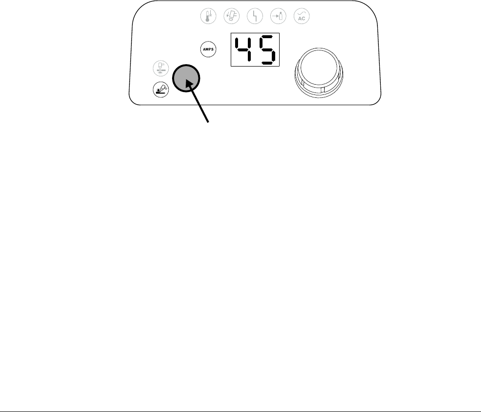
Operation
2
58 809240 Operator Manual Powermax45 XP
Reset the gas pressure
When you manually adjust the gas pressure, the pressure you set remains in place until you reset it.
You can reset the gas pressure by pressing the Mode button.
When you reset the gas pressure, the selected mode LED stops blinking.
The gas pressure also resets to the default setting when:
You are in gouge/marking mode and you change the output current from:
The Maximum Control gouging process (26 – 45 A) to the Precision gouging process
(10 – 25 A)
The Precision gouging process (10 – 25 A) to the Maximum Control gouging process
(26 – 45 A)
You connect a different torch to the power supply.
Turning the power supply OFF and ON does not reset the gas pressure.
Press the button to reset the gas pressure.
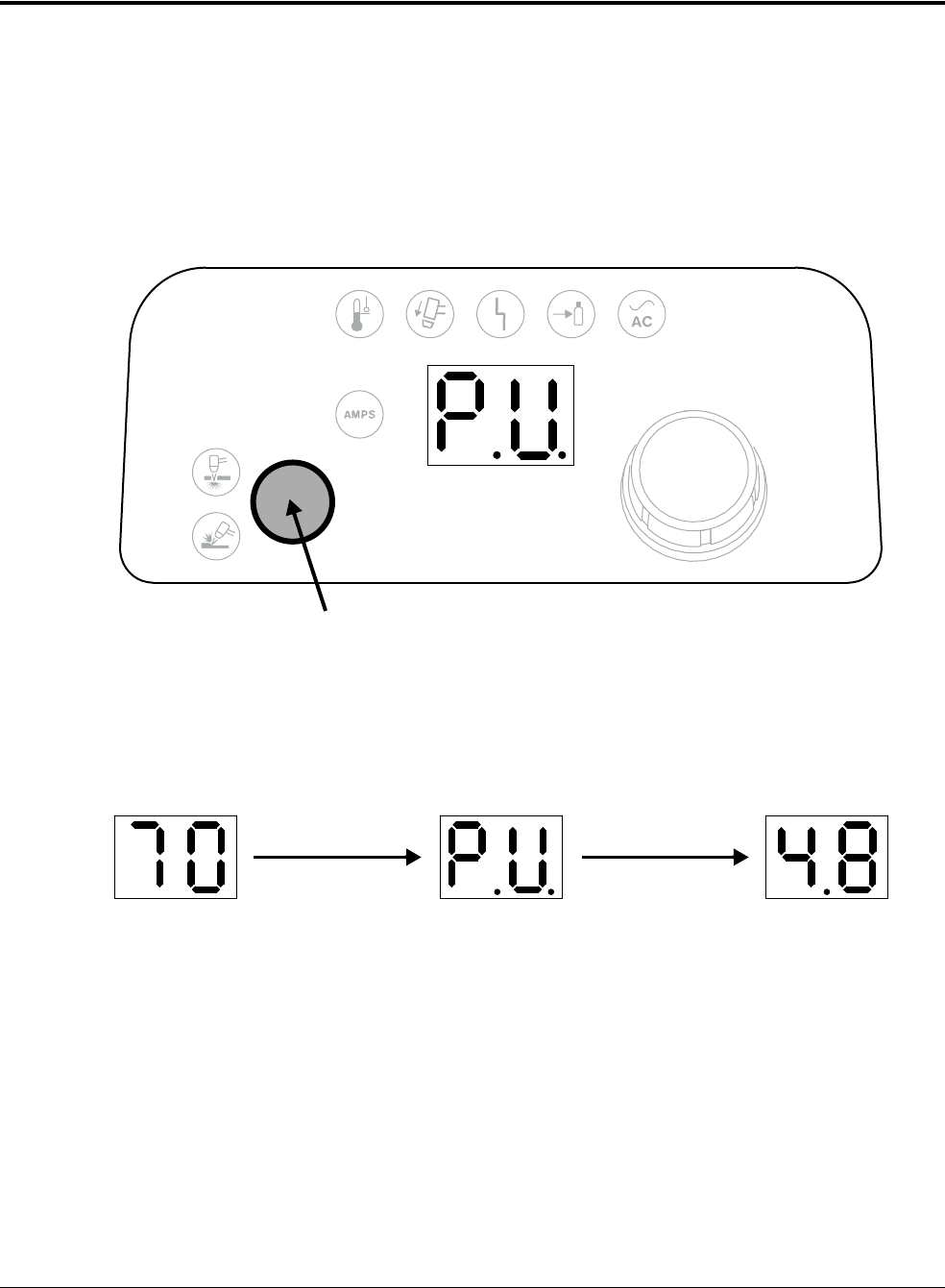
Operation
2
Powermax45 XP Operator Manual 809240 59
Change the gas pressure values between psi and bar
CSA models: The gas pressure displays in psi by default.
CE/CCC models: The gas pressure displays in bar by default.
To change the gas pressure display values from psi to bar or from bar to psi:
1. Press-and-hold the Mode button for approximately 15 seconds until the 2-digit display
shows P.U.
2. Release the Mode button. The system will now display gas pressure values in bar instead of psi
or in psi instead of bar.
Press-and-hold for 15 seconds to toggle between psi and bar.
psi bar
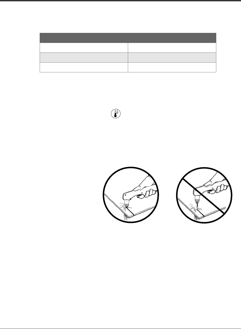
Operation
2
60 809240 Operator Manual Powermax45 XP
Understand duty cycle to prevent overheating
Duty cycle – Percentage of time during a 10-minute interval that a plasma arc can remain on
without causing the system to overheat.
When you exceed the duty cycle and the system overheats:
The plasma arc shuts off.
The Temperature LED illuminates.
The cooling fan inside the power supply runs.
When the system overheats:
a. Leave the system on to allow the fan to cool the power supply.
b. Wait for the Temperature LED to turn off before you start to cut again.
Stretching the plasma arc for
prolonged periods negatively
impacts duty cycle. Whenever
possible, drag the torch on the
workpiece. See Start a cut from
the edge of the workpiece on
page 72.
If you operate the system on a
lower rated electrical service,
stretching the plasma arc for
prolonged periods can cause the
system to overheat more quickly
and can cause the circuit breaker
to trip. See Decrease output
current and arc stretch for lower
rated electrical service on
page 34.
Output current Duty cycle*
45 A 50%
41 A 60%
32 A 100%
* Assumes ambient operating temperature of 40°C (104°F).

Powermax45 XP Operator Manual 809240 61
Cut with the Hand Torch
Duramax Lock hand torches come in 15° and 75° models.
The 75° hand torch is a general purpose torch designed for the widest range of applications.
The 15° hand torch is designed to direct heat away from the operator during heavy gouging.
It also facilitates cutting overhead or in hard to reach areas.
Duramax Lock torch features include:
A torch-disable switch that prevents the torch from firing accidentally even when the power
supply is ON. See Disable the torch on page 46.
The FastConnect
TM
quick-disconnect system to easily remove the torch for transport or to
switch from one torch to another.
Automatic cooling with ambient air. Special cooling procedures are not needed.
This section provides an overview of hand torch parts, dimensions, consumables, cutting guidelines,
and basic cutting methods. For gouging information, see Gouge with the Hand Torch and Machine
Torch on page 75.
To resolve issues with cut quality, refer to Common cutting issues on
page 144.
The Duramax Lock hand torches ship without consumables installed. To install the consumables,
see page 48.
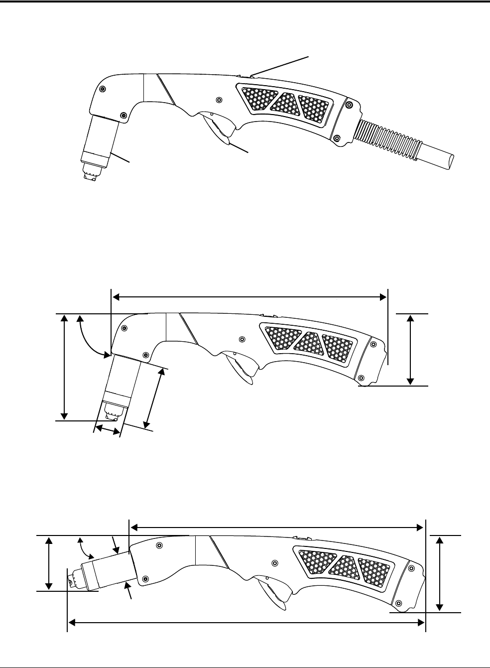
Cut with the Hand Torch
3
62 809240 Operator Manual Powermax45 XP
Hand torch components, dimensions, weights
Components
Dimensions
75° hand torch
15° hand torch
Consumables
Safety trigger
Torch-disable switch
260 mm (10.2 inch)
102 mm
(4.0 inch)
75°
61 mm (2.4 inch)
25 mm (1.0 inch)
69 mm
(2.7 inch)
269 mm (10.6 inch)
51 mm
(2.0 inch)
69 mm
(2.7 inch)
15°
325 mm (12.8 inch)
25 mm (1.0 inch)
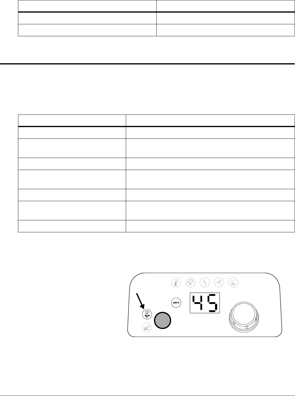
Cut with the Hand Torch
3
Powermax45 XP Operator Manual 809240 63
Weights
Choose the consumables
The 15° and 75° Duramax Lock hand torches use the same consumables.
Your system ships with a starter consumable kit that includes the shielded consumables on page 64
plus 1 extra electrode and 1 extra nozzle.
When you use the following
shielded and FineCut
consumables, select Cut mode
on the front panel. See page 53.
Torch Weight
Hand torch with 6.1 m (20 foot) lead 1.8 kg (3.9 pounds)
Hand torch with 15 m (50 foot) lead 3.7 kg (8.1 pounds)
Consumable Type Purpose
Shielded drag-cutting Drag cut for the widest range of cutting applications.
FineCut
®
Achieve narrower kerf on thin mild steel and stainless steel up to
3mm (10gauge).
HyAccess
TM
Cut or gouge in hard to reach areas or confined spaces.
FlushCut
TM
Cut as close to the base as possible without piercing or
damaging the workpiece.
Maximum Control gouging (26 – 45 A)* Remove metal and achieve a controlled gouge profile.
Precision gouging (10 – 25 A)*
Achieve very shallow gouge and lower metal removal rate than
with Maximum Control gouging, such as for spot weld removal.
Marking (10 – 25 A)
†
Mark metal surfaces using air or argon.
* For details on gouging processes and consumables, see Gouging processes on page 75.
†
For details on marking consumables, see Marking consumables (10 – 25 A) on page 119.
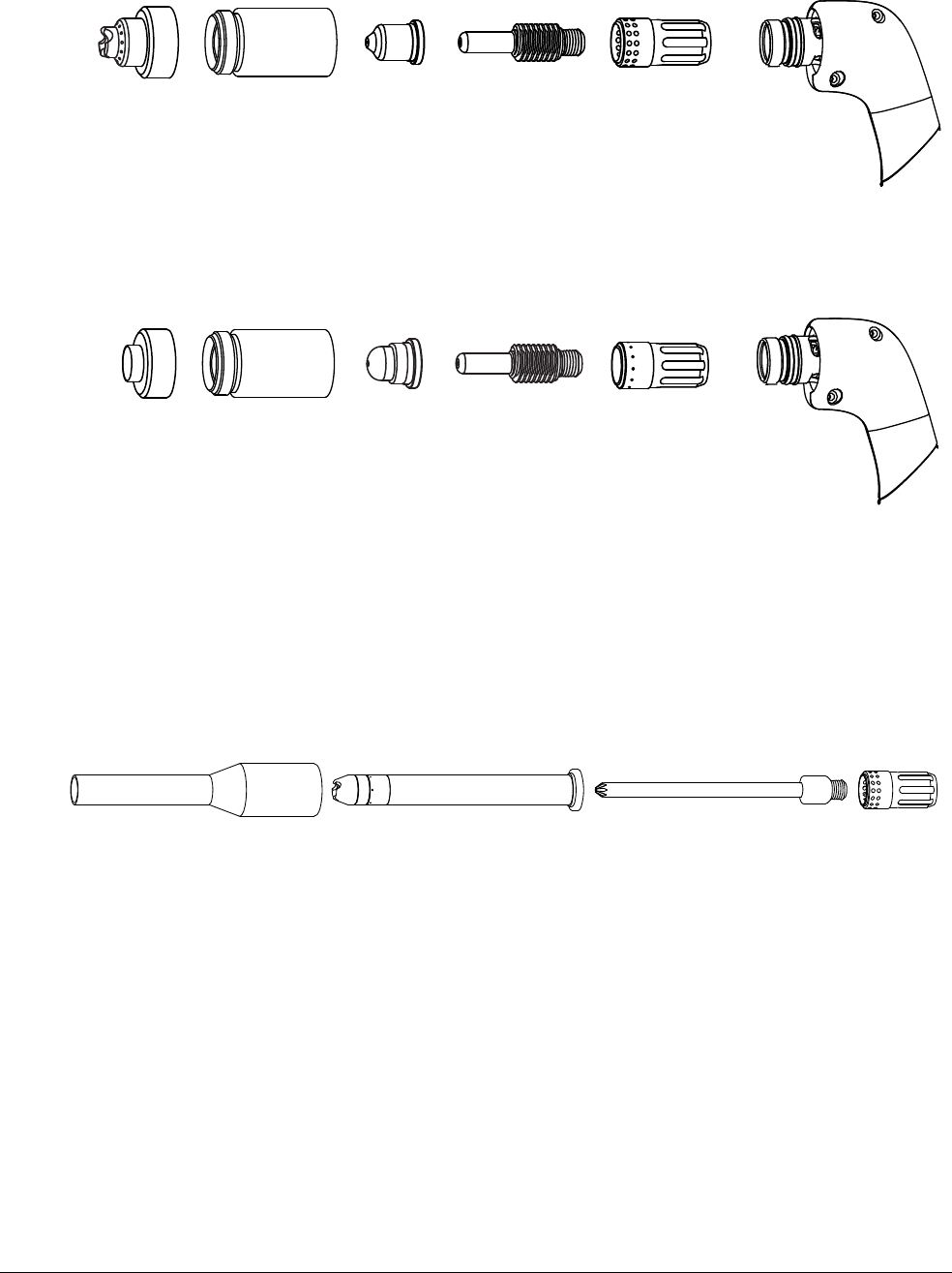
Cut with the Hand Torch
3
64 809240 Operator Manual Powermax45 XP
Shielded drag-cutting consumables
FineCut consumables
Specialty consumables
HyAccess cutting consumables
HyAccess consumables extend the reach of the regular shielded consumables by approximately
7.5 cm (3 inches). Use them with your hand torch to achieve greater reach and visibility.
HyAccess gouging consumables are also available. See page 77.
You can expect to cut approximately the same thicknesses as with the regular shielded
consumables. You may need to reduce your cut speed slightly to achieve the same cut quality.
Typically, you can expect HyAccess consumables to last approximately half as long as the regular
shielded consumables.
220818
Shield
220854
Retaining cap
220941
Nozzle
220857
Swirl ring
220842
Electrode
220931
Deflector
220854
Retaining cap
220930
Nozzle
220947
Swirl ring
220842
Electrode
420410
Cutting nozzle
420408
Electrode
220857
Swirl ring
420413
Retaining cap
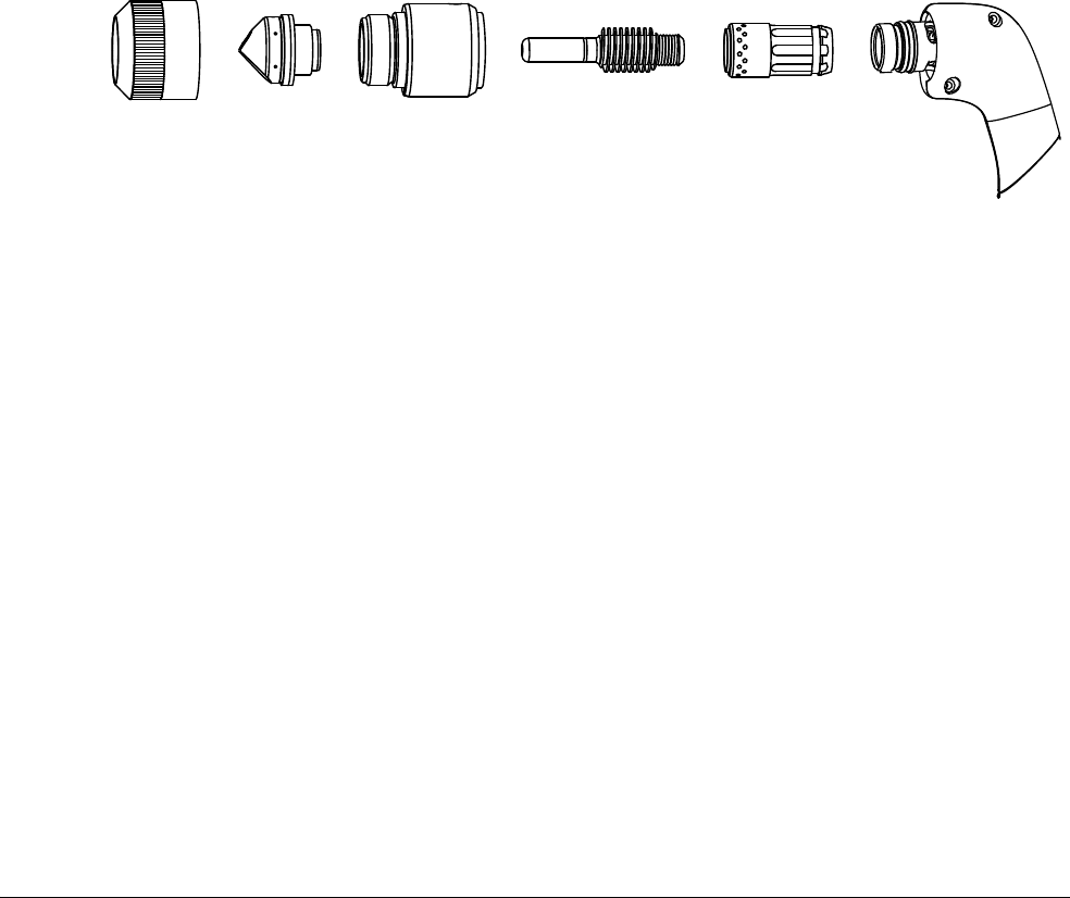
Cut with the Hand Torch
3
Powermax45 XP Operator Manual 809240 65
You can order each HyAccess consumable separately or in starter kits. When the tip of the nozzle
wears out, replace the entire nozzle.
The 428445 cutting starter kit contains:
1 HyAccess electrode
1 HyAccess cutting nozzle
1 HyAccess retaining cap
The 428414 cutting/gouging starter kit contains:
2 HyAccess electrodes
1 HyAccess cutting nozzle
1 HyAccess gouging nozzle
1 HyAccess retaining cap
1 swirl ring (standard Powermax45 XP swirl ring)
FlushCut™ consumables
FlushCut consumables are designed to remove lugs, pad eyes, and other attachments without
piercing or damaging the workpiece underneath. FlushCut consumables produce an angled plasma
arc that enables you to cut very close to the base material without leaving a large amount of residual
material to grind off.
You can expect to cut approximately the same thicknesses as with the regular shielded
consumables. However, make sure to account for any added thickness that may be present from
weld beads. Consumable life will vary, but typically you can expect FlushCut consumables to last
approximately 3/4 as long as the regular shielded consumables.
You can order FlushCut consumables individually or in a starter kit (428746) that contains 1 of each
consumable shown above. If you order FlushCut consumables individually:
The minimum order quantity for the electrode is 5.
All other FlushCut consumables can be ordered in single quantities.
420633
Nozzle
420635
Electrode
420634
Swirl ring
420540
Retaining ring
420536
Cap
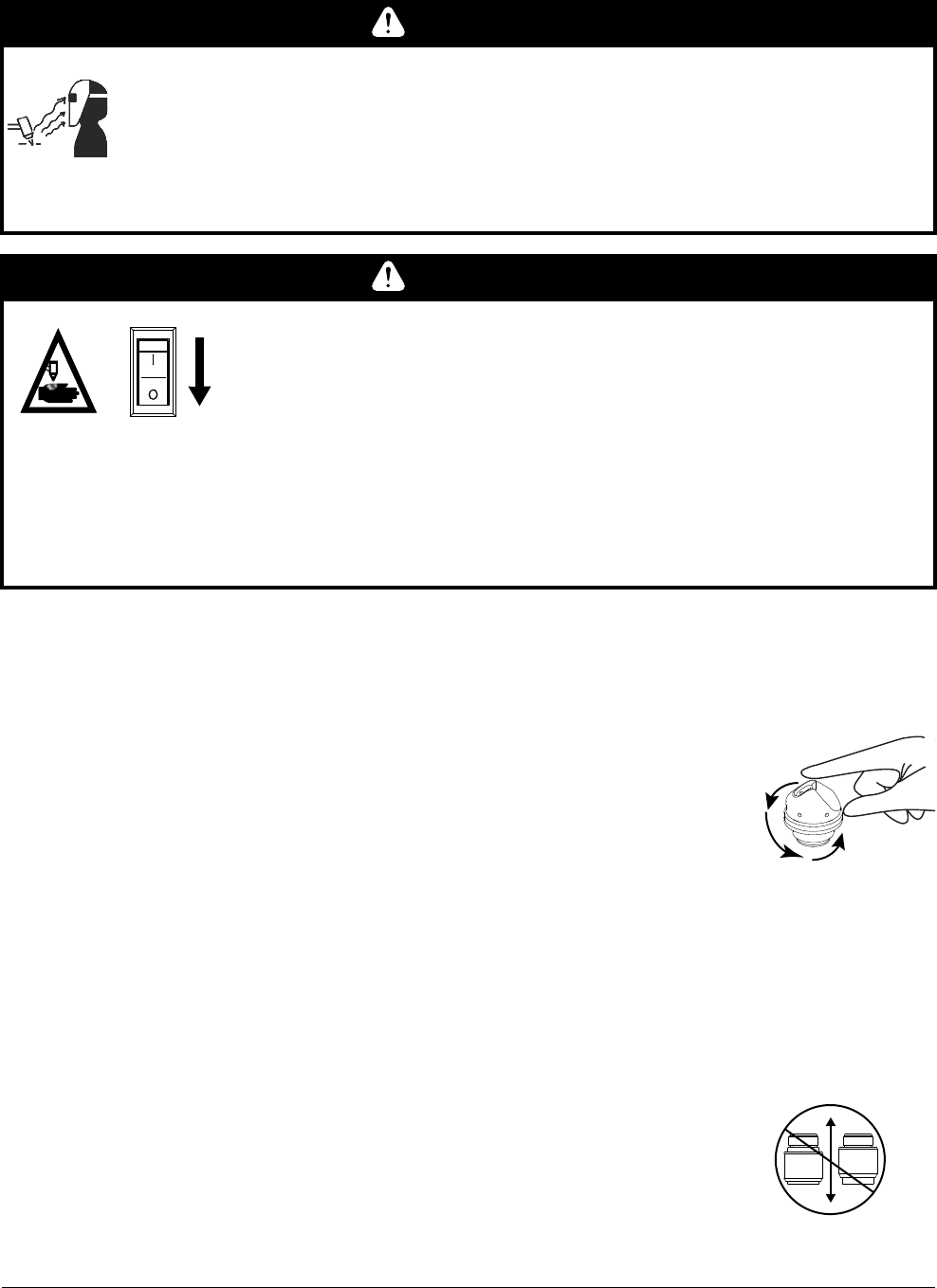
Cut with the Hand Torch
3
66 809240 Operator Manual Powermax45 XP
To install:
1. Turn O F F (O) the power supply, or set the torch-disable switch to the yellow lock (X) position.
2. Put the swirl ring, electrode, cap, and nozzle on the torch. Rotate the
nozzle based on the direction you plan to cut. Make sure the flat side of
the nozzle is on the bottom so you can drag it along the workpiece.
3. Fully tighten the retaining ring onto the cap.
Repeat these steps while cutting if you need to change the orientation of
the nozzle in order to complete the cut.
Tips:
Drag the flat side of the nozzle along the base, but maintain a standoff of approximately
3 mm – 6 mm (1/8 inch to 1/4 inch) from the vertical workpiece you are cutting.
You can use the FlushCut consumables in Gouge/Marking mode to remove residual material
from the base workpiece. Turn down the amperage as needed.
Replace the cap when the outer sleeve no longer slides freely up
and down.
WARNING
ARC RAYS CAN BURN EYES AND SKIN
When you use FlushCut consumables, wear a face shield that covers your entire
face. Use a shield with a shade 10 lens.
Plasma arc rays produce intense visible and invisible (ultraviolet and infrared) rays
that can burn eyes and skin.
WARNING
INSTANT-ON TORCHES – PLASMA ARC CAN CAUSE INJURY, BURNS
Before rotating the FlushCut nozzle, one of the following actions must
be taken. Whenever possible, complete the first action.
Turn OFF (O) the plasma power supply.
OR
Move the torch-disable switch to the yellow lock (X) position
(closest to the torch lead). Pull the trigger to make sure the
torch does not fire a plasma arc.

Cut with the Hand Torch
3
Powermax45 XP Operator Manual 809240 67
CopperPlus™ electrode
The CopperPlus electrode (220777) delivers at least
2 times longer consumable life over standard consumables
(Hypertherm consumables designed for the system). This
electrode is designed exclusively for use with Duramax and
Duramax Lock torches when cutting metal up to 12 mm
(1/2 inch).
Consumable life
Many factors influence how often you need to change the consumables on your hand torch:
Poor gas supply quality
It is extremely important to maintain a clean, dry gas line. The presence of oil, water,
vapor, and other contaminants in the gas supply can degrade cut quality and
consumable life. See page 38 and page 42.
Cutting technique
Whenever possible, start cuts from the edge of the workpiece. This helps to extend the
life of the shield and the nozzle. See page 72.
Use the proper piercing technique for the thickness of metal you are cutting. In many
instances, a rolling pierce technique is an efficient way to pierce the metal while
minimizing the consumable wear that naturally occurs during piercing. See page 73 for
an explanation of the straight pierce and rolling pierce techniques and when each is
appropriate.
Shielded versus non-shielded consumables
Non-shielded consumables use a deflector instead of a shield. They can provide better
visibility and accessibility for some cutting applications. The trade-off is that
non-shielded consumables generally have a shorter life than shielded consumables.
Thickness of metal being cut
In general, the thicker the metal being cut, the more quickly the consumables become
worn. For best results, do not exceed the thickness specifications for this system. See
page 24.
See page 165 for guidelines on when to replace worn consumables.
Expanded metal cutting
Expanded metal has a slotted or mesh pattern. Cutting expanded metal wears out
consumables more quickly because it requires a continuous pilot arc. A pilot arc occurs
when the torch is fired but the plasma arc is not in contact with the workpiece.
220777

Cut with the Hand Torch
3
68 809240 Operator Manual Powermax45 XP
Incorrect consumables for output current and mode
To optimize consumable life, make sure the consumables installed on the torch match
the selected mode and output current. For example:
Do not use gouging consumables when the system is set to Cut mode. See
page 53.
Do not set the output current between 26 A and 45 A with the Precision gouging
consumables installed.
Unnecessary arc stretch when cutting
To maximize consumable life, avoid stretching the arc when it is not necessary. Drag the
torch on the workpiece whenever possible. See page 71.
Insufficient arc stretch when gouging
A proper arc stretch while gouging maintains distance between the torch tip and the
molten metal that builds up during the gouge. See page 79.
An arc stretch of 19 – 25 mm (3/4 – 1 inch) is recommended for gouging with the
Maximum Control gouging consumables at 26 – 45 A.
An arc stretch of 10 – 11 mm (3/8 – 1/2 inch) is recommended for gouging with the
Precision gouging consumables at 10 A– 25 A.
As a general rule, the consumables last approximately 1 to 2 hours of actual “arc on” time for hand
cutting. However, consumable life can vary a lot based on the factors listed above. See Inspect the
consumables on page 165 for information on the signs of wear to look for in consumables.
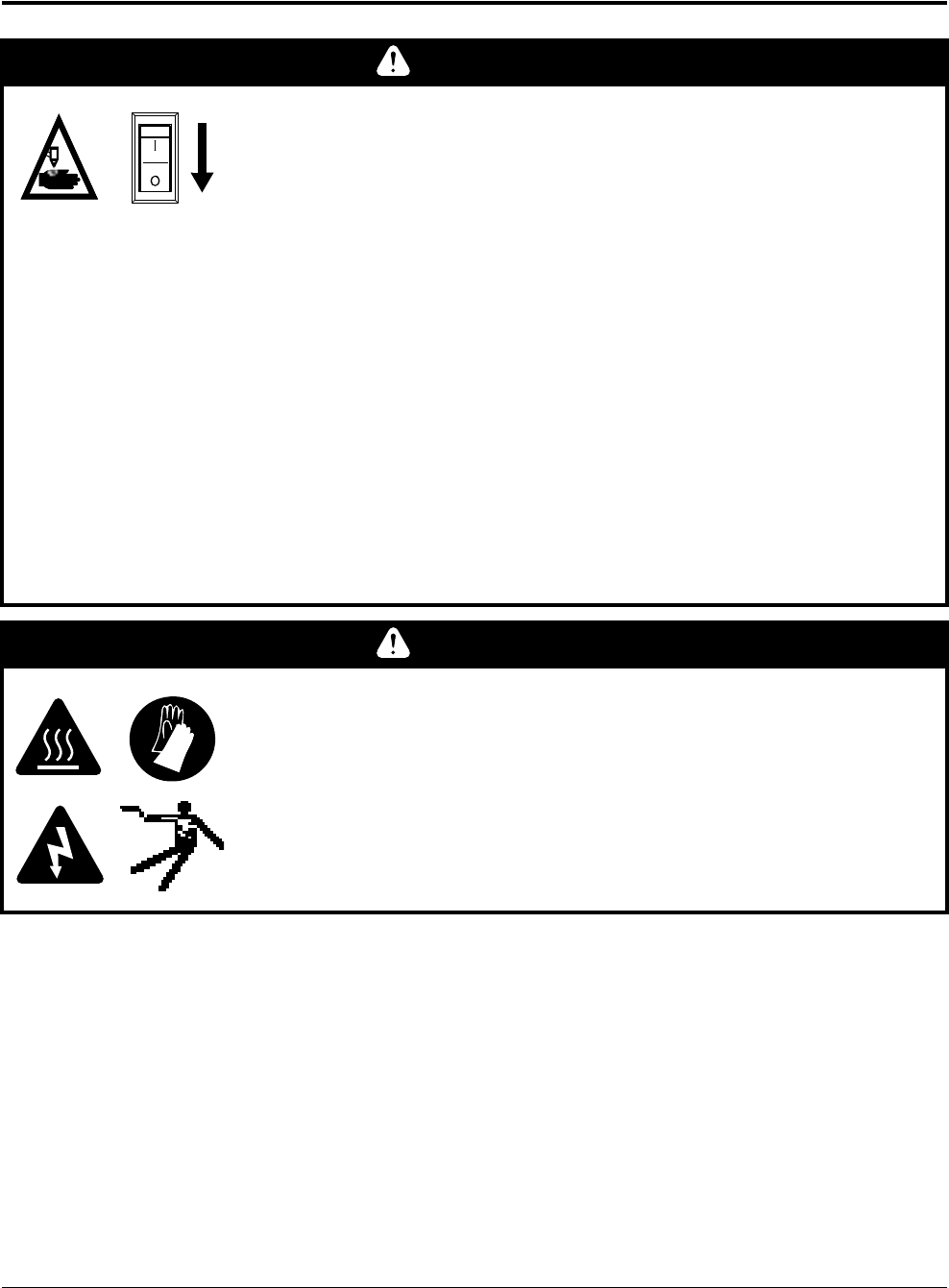
Cut with the Hand Torch
3
Powermax45 XP Operator Manual 809240 69
Prepare to fire the torch
To prevent accidental firing, the hand torch is equipped with a torch-disable switch and a safety
trigger. To fire the torch:
1. Install the correct consumables. See page 48.
WARNING
INSTANT-ON TORCHES – PLASMA ARC CAN CAUSE INJURY, BURNS
The plasma arc ignites immediately when you pull the torch trigger.
Before changing consumables, one of the following actions must be
taken. Whenever possible, complete the first action.
Turn OFF (O) the plasma power supply.
OR
Move the torch-disable switch to the yellow lock (X) position
(closest to the torch lead). Pull the trigger to make sure the
torch does not fire a plasma arc.
The plasma arc will cut quickly through gloves and skin.
Wear correct and appropriate protective equipment.
Keep hands, clothing, and objects away from the torch tip.
Do not hold the workpiece. Keep your hands clear of the
cutting path.
Never point the torch toward yourself or others.
WARNING
RISK OF BURNS AND ELECTRIC SHOCK – WEAR INSULATED GLOVES
Always wear insulated gloves when changing the consumables. The
consumables get very hot during cutting and can cause severe burns.
Touching the consumables can also result in electric shock if the power
supply in ON and the torch-disable switch is not in the yellow lock (X)
position.
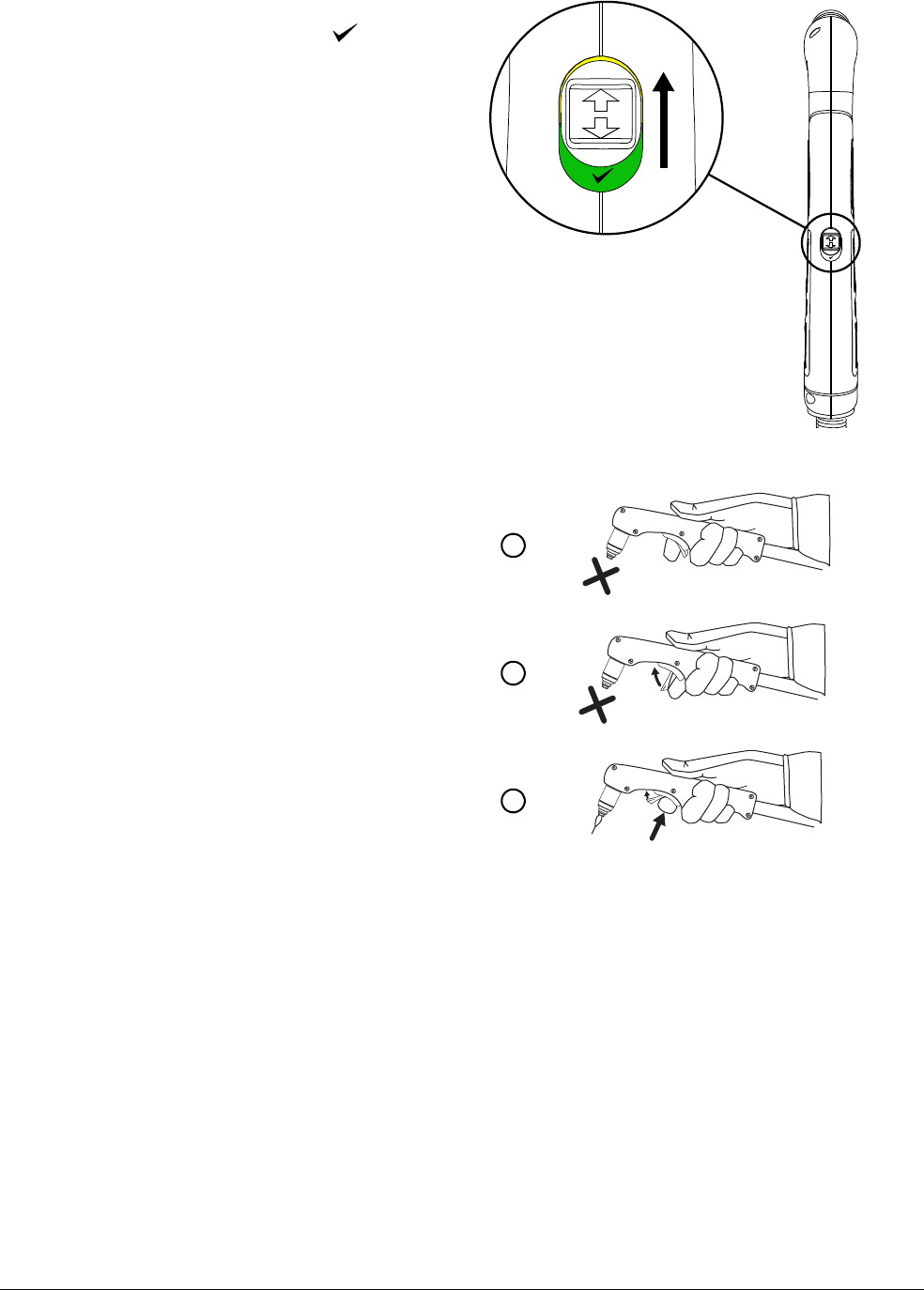
Cut with the Hand Torch
3
70 809240 Operator Manual Powermax45 XP
2. Make sure the torch-disable switch is
in the green “ready to fire” ( )
position.
The first time you pull the
torch trigger after you set the
torch to the “ready to fire”
position, the torch may emit
multiple puffs of air in quick
succession. This warns you
that the torch is active and
will fire an arc the next time
the trigger is pulled.
Seepage47.
3. Flip the trigger’s safety cover forward
(toward the torch head) and press
the red torch trigger.
1
2
3
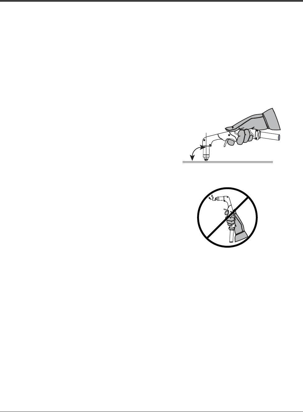
Cut with the Hand Torch
3
Powermax45 XP Operator Manual 809240 71
Hand torch cutting guidelines
Drag the torch tip lightly along the workpiece to maintain a steady cut.
Sometimes the torch sticks slightly to the workpiece when you cut with
FineCut consumables.
Pulling, or dragging, the torch along the cut is easier than pushing it.
If sparks spray up from the workpiece, move the torch more slowly, or set the output current
higher.
While cutting, make sure that sparks exit from the bottom of the workpiece. The sparks
should lag slightly behind the torch as you cut (15° – 30° angle from vertical).
Hold the torch tip perpendicular to the
workpiece so that the head of the
torch is at a 90° angle to the cutting
surface. Observe the cutting arc as the
torch cuts.
If you fire the torch unnecessarily, you
will shorten the life of the nozzle and
electrode.
For straight-line cuts, use a straight
edge as a guide. To cut circles, use a
template or a radius cutter attachment
(a circle cutting guide). For beveled
cuts, use a bevel cutting guide. See
Accessory parts on page 180.
To troubleshoot issues with cut quality, see Common cutting issues on
page 144.
90°

Cut with the Hand Torch
3
72 809240 Operator Manual Powermax45 XP
Start a cut from the edge of the workpiece
Edge starting, when possible, is a good way to reduce damage to the shield and nozzle that can be
caused by the slag produced during piercing. This helps to optimize consumable life.
1. With the work clamp attached to the workpiece, hold the torch tip perpendicular (90°) to the
edge of the workpiece.
2. Press the torch’s trigger to start the arc. Pause at the edge until the arc has cut completely
through the workpiece.
3. Drag the torch lightly across the workpiece to proceed with the cut. Maintain a steady, even
pace.

Cut with the Hand Torch
3
Powermax45 XP Operator Manual 809240 73
Pierce a workpiece
The hand torch can pierce interior features on metal with a thickness of up to 12 mm (1/2 inch).
The type of pierce to perform depends on the thickness of the metal.
Straight pierce – To cut metal that is thinner than 8 mm (5/16 inch).
Rolling pierce – To cut metal that is 8 mm (5/16 inch) or thicker.
1. Attach the work clamp to the workpiece.
2. Straight pierce: Hold the torch perpendicular (90°) to the workpiece.
Rolling pierce: Hold the torch at an approximate 30° angle to the workpiece with the torch tip
within 1.5 mm (1/16 inch) of the workpiece before firing the torch.
WARNING
SPARKS AND HOT METAL CAN INJURE EYES AND BURN SKIN
When firing the torch at an angle, sparks and hot metal will spray out from the
nozzle. Point the torch away from yourself and others. Always wear proper protective
equipment including gloves and eye protection.
30° for rolling pierce
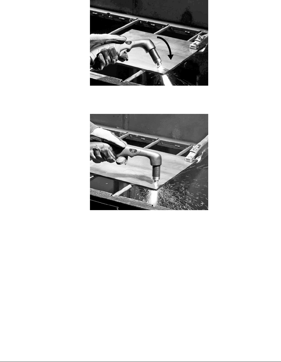
Cut with the Hand Torch
3
74 809240 Operator Manual Powermax45 XP
3. Straight pierce: Press the torch trigger to start the arc.
Rolling pierce: Press the torch trigger to start the arc while still at an angle to the workpiece,
then rotate the torch to the perpendicular (90°) position.
4. Hold the torch in place while continuing to press the trigger. When sparks exit below the
workpiece, the arc has pierced the material.
5. When the pierce is complete, drag the torch tip lightly along the workpiece to proceed with the
cut.

Powermax45 XP Operator Manual 809240 75
Gouge with the Hand Torch and Machine Torch
Gouging processes
This system offers 2 gouging processes. Each process uses its own set of consumables:
Maximum Control gouging
Use this process to remove metal and to achieve a controlled gouge profile.
Precision gouging
Use this process to achieve a very shallow gouge and a lower metal removal rate than
with Maximum Control gouging. For example, this process is useful for removing spot
welds and for washing material at very low depths.
Before you use either process, press the Mode button on the front panel to set the plasma power
supply to Gouge/Marking mode. See page 53.
Make sure the Gouge/Marking Mode LED is illuminated.
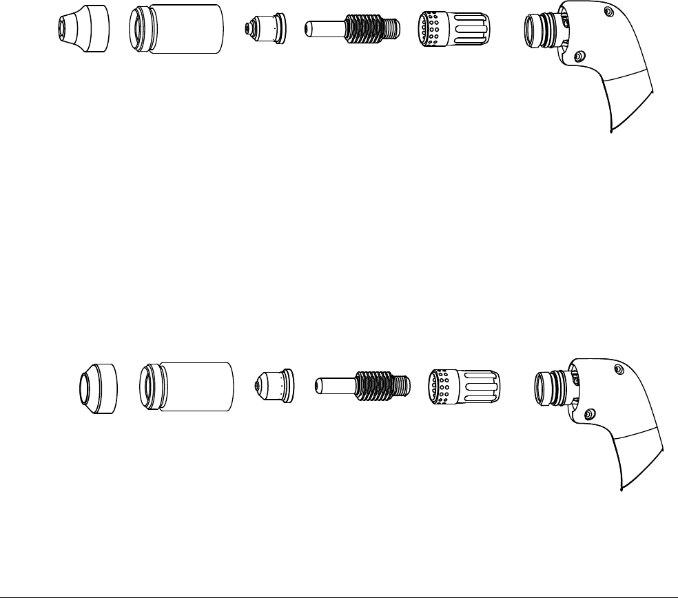
Gouge with the Hand Torch and Machine Torch
4
76 809240 Operator Manual Powermax45 XP
Maximum Control gouging
Use the Maximum Control gouging consumables.
Hypertherm also offers Maximum Removal gouging consumables. At
higher amperages on other Powermax systems, you can use the Maximum
Removal consumables for greater metal removal rate and deeper gouge
profiles. However, at 45 A with this system and torch, the Maximum
Removal consumables do not offer an advantage over the Maximum
Control consumables in terms of metal removal rate. You can expect each
set of consumables to produce similar results on this system.
Set the output current between 26 A and 45 A.
Gouging at lower amperages (10 – 25 A) can limit the torch’s arc stretch capability. In
some instances it may also cause the arc to extinguish or trigger a “torch stuck open”
(TSO) fault. See page 156.
Maximum Control gouging consumables (26 – 45 A)
Precision gouging
Use the Precision gouging consumables.
Set the output current between 10 A and 25 A.
Gouging at higher amperages (26 – 45 A) can shorten the life of the nozzle.
Precision gouging consumables (10 – 25 A)
420419
Nozzle
420480
Shield
220854
Retaining cap
220857
Swirl ring
220842
Electrode
220854
Retaining cap
420415
Nozzle
220857
Swirl ring
220842
Electrode
420414
Deflector

Gouge with the Hand Torch and Machine Torch
4
Powermax45 XP Operator Manual 809240 77
Specialty consumables
HyAccess gouging consumables
HyAccess consumables extend the reach of the regular shielded consumables by approximately
7.5 cm (3 inches). Use them with your hand torch to achieve greater reach and visibility.
HyAccess cutting consumables are also available. For more information
on HyAccess consumables, see page 64.
You can order each HyAccess consumable separately or in starter kits. When the tip of the nozzle
wears out, replace the entire nozzle.
The 428446 gouging starter kit contains:
1 HyAccess electrode
1 HyAccess gouging nozzle
1 HyAccess retaining cap
The 428414 cutting/gouging starter kit contains:
2 HyAccess electrodes
1 HyAccess cutting nozzle
1 HyAccess gouging nozzle
1 HyAccess retaining cap
1 swirl ring (standard Powermax45 XP swirl ring)
420412
Gouging nozzle
420408
Electrode
220857
Swirl ring
420413
Retaining cap
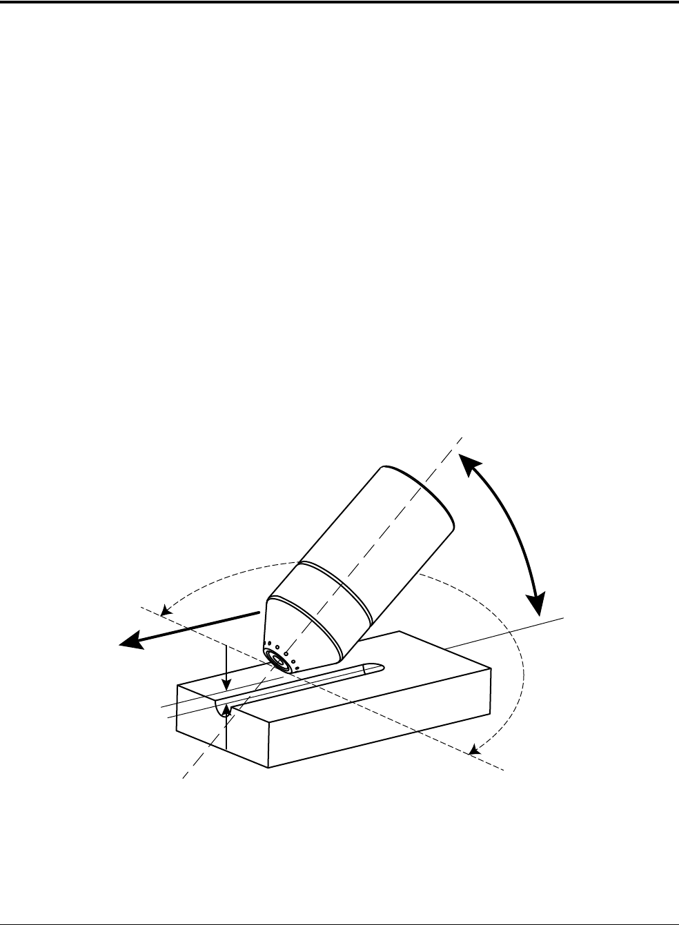
Gouge with the Hand Torch and Machine Torch
4
78 809240 Operator Manual Powermax45 XP
How to control the gouge profile
The following factors affect the width and the depth of the gouge profile. Adjust these elements to
achieve the gouge you need.
Output current of the plasma power supply – Turn down the amperage on the front panel
to make the gouge narrower and more shallow.
If you are using the Maximum Control gouging consumables, keep the amperage
between 26 – 45 A.
If you are using the Precision gouging consumables, keep the amperage between
10 – 25 A.
Angle of the torch to the workpiece – Position the torch in a more upright position to
make the gouge narrower and deeper. Tilt down the torch so that it is closer to the
workpiece to make the gouge wider and more shallow.
Rotation of the torch – Rotate the torch relative to the torch center line to make the gouge
flatter and steeper on one side.
Torch-to-work standoff – Move the torch further away from the workpiece to make the
gouge wider and more shallow. Move the torch closer to the workpiece to make the gouge
narrower and deeper.
Speed of the torch over the workpiece – Slow down to make the gouge wider and
deeper. Speed up to make the gouge narrower and more shallow.
Standoff
Angle
Rotation of torch (relative
to torch center line)
Torch center line
Speed
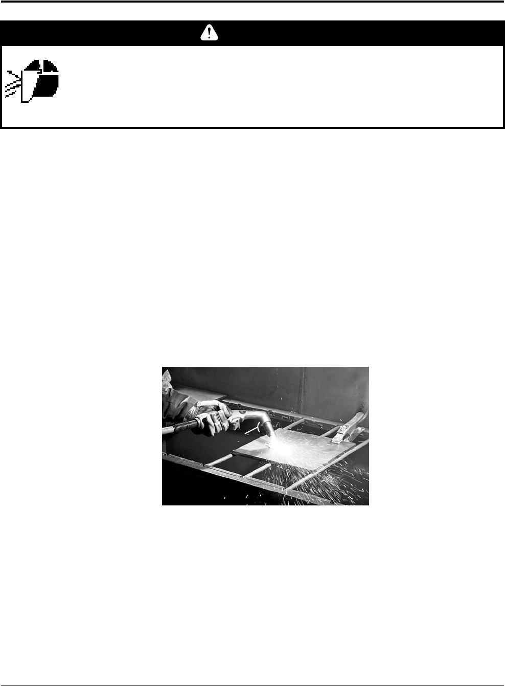
Gouge with the Hand Torch and Machine Torch
4
Powermax45 XP Operator Manual 809240 79
Gouge with the hand torch
1. Install the Maximum Control gouging consumables or the Precision gouging consumables.
2. Set the system to Gouge/Marking mode. See page 53.
3. Set the output current to match the consumables installed:
Maximum Control gouging consumables: 26 – 45 A
Precision gouging consumables: 10 – 25 A
4. Hold the torch at approximately a 40° angle to the workpiece before firing the torch.
Maximum Control gouging consumables: Hold the torch approximately 6 mm (1/4 inch)
above the workpiece.
Precision gouging consumables: Hold the torch approximately 2 – 3 mm above the
workpiece.
Press the trigger to obtain a pilot arc. Transfer the arc to the workpiece.
5. Stretch the arc as follows:
Maximum Control gouging consumables: 19 – 25 mm (3/4 – 1 inch)
Precision gouging consumables: 10 – 11 mm (3/8 – 1/2 inch)
WARNING
SPARKS AND HOT METAL CAN INJURE EYES AND BURN SKIN
When firing the torch at an angle, sparks and hot metal will spray out from the
nozzle. Point the torch away from yourself and others. Always wear proper protective
equipment including gloves and eye protection.
40°

Gouge with the Hand Torch and Machine Torch
4
80 809240 Operator Manual Powermax45 XP
6. Change the torch’s angle as needed to achieve the desired dimensions for the gouge. Maintain
the same angle to the workpiece as you feed into the gouge. Push the plasma arc in the
direction of the gouge you want to create.
Keep at least a small distance between the torch tip and the molten metal
to avoid reducing consumable life or damaging the torch.
Remove spot welds
To remove a spot weld, gouge around the weld in order to cut completely through the top layer of
metal without damaging the layer underneath.
The Precision gouging consumables were designed specifically for applications like removing spot
welds. When used at a lower amperage, these consumables provide:
Very good visibility due to a plasma arc that is less bright and that allows you to see the
metal being gouged more clearly
A very high width-to-depth ratio, which provides much better control of the metal removal
rate
Tips
Many different techniques can be used to remove spot welds. The method described in the
following procedure is recommended as a good starting point. It is intended to minimize possible
damage to the underneath layer.
Regardless of technique, these tips can help you to successfully remove spot welds:
Keep the torch pointed in the same direction all the way around the spot weld.
By keeping the torch pointed in the same direction, you avoid blowing slag over areas
you already gouged. This reduces the clean-up needed on the underneath layer. It also
makes the process more ergonomic and efficient, since you do not need to rotate the
torch or the workpiece while gouging.
Maintain a proper arc stretch.
Maintain an arc stretch of approximately 10 – 11 mm (3/8 – 1/2 inch) as you gouge
around the weld. This provides good visibility and prevents the torch tip from hitting slag,
which can shorten consumable life and interrupt the gouge.
Direction of
travel
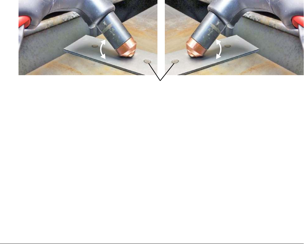
Gouge with the Hand Torch and Machine Torch
4
Powermax45 XP Operator Manual 809240 81
Start at a lower output current, and gradually increase it.
Start with the current set to 10 A if you have never removed a spot weld before. Once
you develop a technique you are comfortable with, try gradually increasing the output
current. This enables you to gouge with better speed and efficiency.
Procedure
This procedure describes how to separate 2 metal layers and then remove the spot weld from the
underneath layer.
The pictures in this procedure show mild steel plates. The slag on
stainless steel is darker, more jagged, and harder to remove.
1. Install the Precision gouging consumables.
2. On the front panel, select Gouge/Marking mode. Set the output current to 10 – 25 A.
3. Position the torch on one side of the spot weld. Hold the torch at approximately a 40° – 45°
angle to the workpiece.
4. Press the trigger to obtain a pilot arc. Transfer the arc to the workpiece, then stretch the arc to
approximately 10–11mm (3/8–1/2inch). Maintain this arc as you gouge.
5. Make 2 separate gouges in an “L”-shaped motion to gouge all the way around the spot weld.
See Table 1 on page 82.
Table 1 shows one example of this technique (for both right-handed and left-handed
gouging). You can start at different points around the spot weld. The important thing is
to keep the torch pointed in the same direction all the way around the weld.
As you gouge, use very short strokes in a back-and-forth weaving motion until you have
cut through the top layer.
You may need to adjust the angle of the torch slightly, depending on the thickness of the
metal.
40° – 45°
Spot weld
40° – 45°
Left-handed approach Right-handed approach
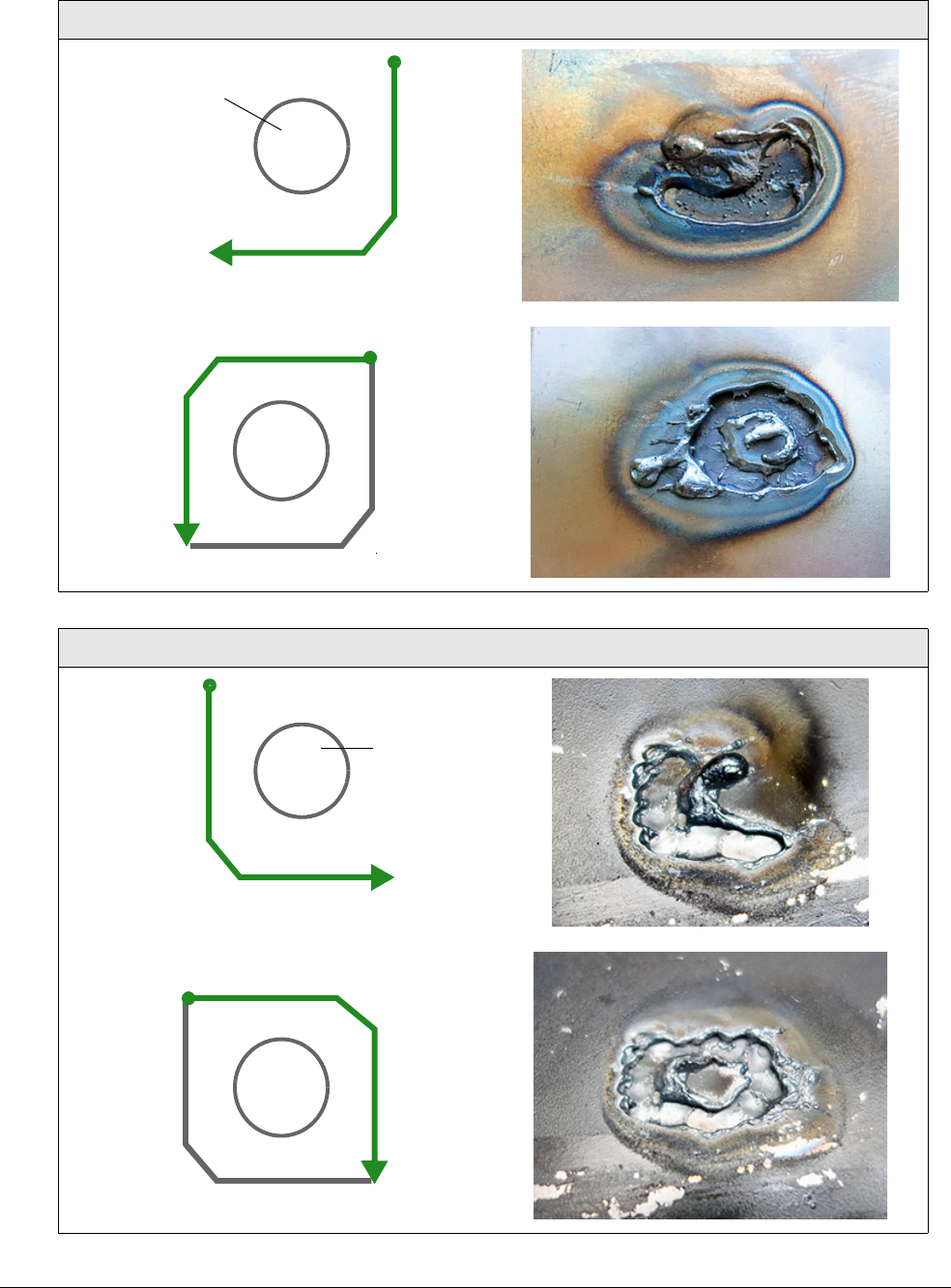
Gouge with the Hand Torch and Machine Torch
4
82 809240 Operator Manual Powermax45 XP
Table 1 – Gouging around the spot weld
Right-handed approach
Left-handed approach
Spot weld
Start
Stop
Start
Stop
Spot weld
Start
Stop
Start
Stop
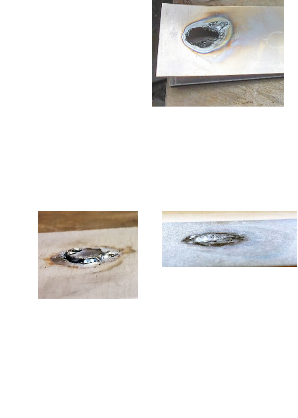
Gouge with the Hand Torch and Machine Torch
4
Powermax45 XP Operator Manual 809240 83
6. Make sure you have gouged
completely through the top layer. Pull
the metal plates apart.
7. Use the same gouging process to
remove the spot weld that remains on
the bottom plate.
To avoid damaging the
bottom plate, you may want
to turn down the output
current to 10 A. Increase the
current if needed based on
the thickness of the metal.
Hold the torch at a 40° – 45°
angle. Slightly adjust the
angle of the torch as needed based on the thickness of the metal.
Stretch the arc to approximately 10 – 11 mm (3/8 – 1/2 inch) as you gouge.
Use very short strokes in a back-and-forth weaving motion until you have removed the
spot weld.
Some scraping or grinding may be required to completely remove all
remnants of the spot weld from the bottom plate.
Spot weld on bottom plate Spot weld removed
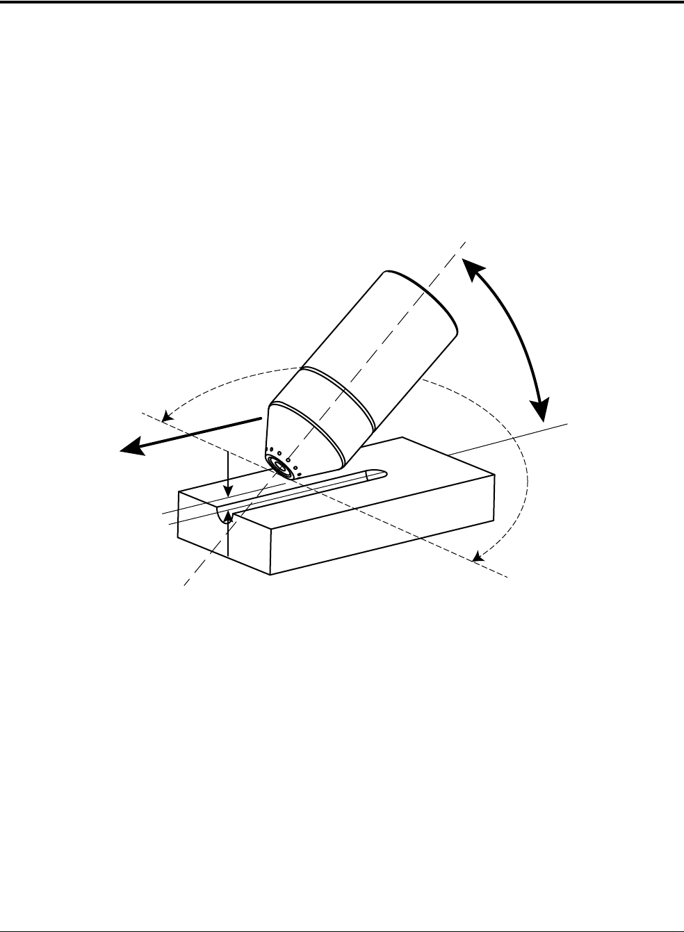
Gouge with the Hand Torch and Machine Torch
4
84 809240 Operator Manual Powermax45 XP
Gouge with the machine torch
You can vary the gouge profile by adjusting the:
Output current (amperage) of the power supply
Angle of the torch to the workpiece
Rotation of the torch relative to the torch center line
Torch-to-work st andoff
Speed of the torch over the workpiece
See page 78 for more details.
Standoff
Angle
Rotation of torch (relative
to torch center line)
Torch center line
Speed
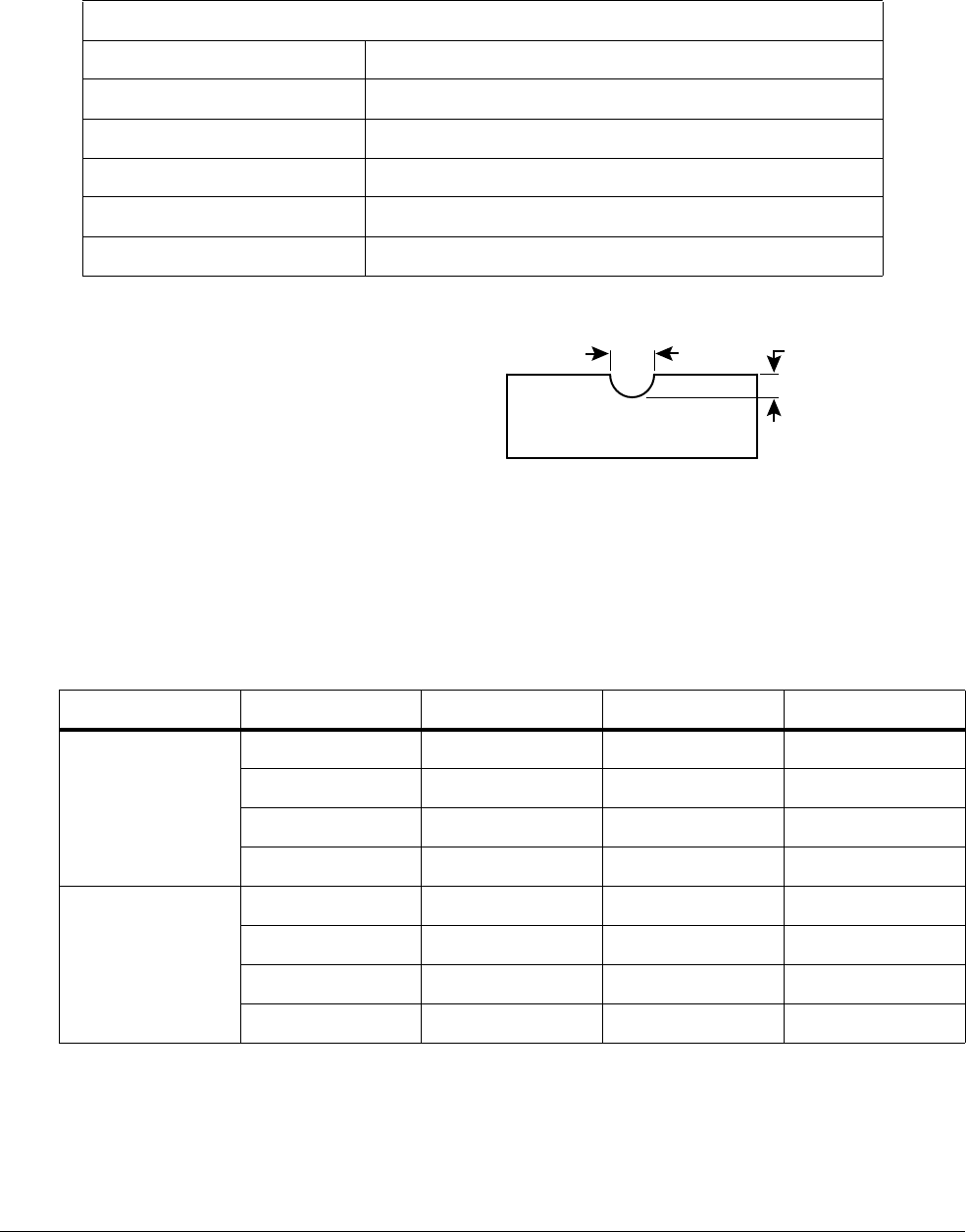
Gouge with the Hand Torch and Machine Torch
4
Powermax45 XP Operator Manual 809240 85
Typical gouge profiles
Maximum Control gouging consumables (45 A)
The following tables show the 45 A gouging profile at 40° and 50° on mild steel and stainless steel.
These settings are intended to serve as a starting point to help you determine the best gouging
profile for a given cutting job. Adjust these settings as needed for your application and table to
obtain the desired result.
Table 2 – Mild steel (Metric)
Operating parameters
Speed 254–1016mm/min (10–40in/min)
Stand off 6mm (1/4inch)
Angle 40° – 50°
Output current 26 – 45 A
Consumables Maximum Control gouging consumables
Gas Air
45 A
Metal removal rate on mild steel:
3.4 kg/hour (7.5 pounds/hour)
Depth
3.2 mm (0.1 inch)
Width
6.8 mm (0.3 inch)
Torch angle Speed (mm/min) Depth (mm) Width (mm) Width/depth ratio
40°
254 4.6 8.4 1.83
508 3.2 6.8 2.13
762 1.9 5.9 3.11
1016 1.4 5.2 3.71
50°
254 5.0 6.7 1.34
508 3.4 5.2 1.53
762 2.7 4.9 1.81
1016 2.2 4.6 2.09

Gouge with the Hand Torch and Machine Torch
4
86 809240 Operator Manual Powermax45 XP
Table 3 – Mild steel (English)
Table 4 – Stainless steel (Metric)
Table 5 – Stainless steel (English)
Torch angle Speed (in/min) Depth (inches) Width (inches) Width/depth ratio
40°
10 0.183 0.331 1.81
20 0.126 0.268 2.13
30 0.074 0.231 3.12
40 0.055 0.206 3.74
50°
10 0.195 0.263 1.35
20 0.132 0.205 1.55
30 0.107 0.192 1.79
40 0.088 0.181 2.06
Torch angle Speed (mm/min) Depth (mm) Width (mm) Width/depth ratio
40°
254 2.9 6.2 2.14
508 2.0 5.7 2.85
1016 1 4.8 4.8
50°
254 5.3 5.7 1.08
508 3.5 5.0 1.43
1016 2.0 3.8 1.90
Torch angle Speed (in/min) Depth (inches) Width (inches) Width/depth ratio
40°
10 0.114 0.245 2.15
20 0.080 0.222 2.76
40 0.048 0.190 3.96
50°
10 0.210 0.224 1.07
20 0.139 0.199 1.43
40 0.080 0.150 1.88
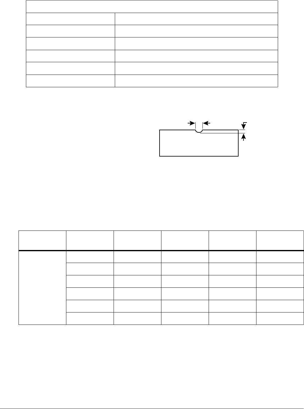
Gouge with the Hand Torch and Machine Torch
4
Powermax45 XP Operator Manual 809240 87
Precision gouging consumables (10 A)
The following tables show the 10 A gouging profile at 40° and 50° on mild steel. These settings are
intended to serve as a starting point to help you determine the best gouging profile for a given
cutting job. Adjust these settings as needed for your application and table to obtain the desired
result.
Table 6 – Mild steel (Metric)
Operating parameters
Speed 254–762mm/min (10–30in/min)
Stand off 0.3–1.3mm (0.01–0.05inch)*
Angle 40° – 50°
Output current 10 – 25 A
Consumables Precision gouging consumables
Gas Air
* Increase the standoff to a maximum of 3 – 4 mm (0.12 – 0.16 inch) for a very light gouge.
10 A
Metal removal rate on mild steel:
0.2 kg/hour (0.5 pounds/hour)
Depth
0.5mm (0.02inch)
Width
2.5 mm (0.1 inch)
Torch angle Standoff (mm)
Speed
(mm/min)
Depth (mm) Width (mm)
Width/depth
ratio
40°
0.3 254 0.5 3.3 6.6
0.3 508 0.3 2.4 8
0.3 762 0.1 2.2 22
1.3 254 0.3 3 10
1.3 508 0.1 2.2 22
1.3 762 0.05 1.9 38

Gouge with the Hand Torch and Machine Torch
4
88 809240 Operator Manual Powermax45 XP
Table 7 – Mild steel (English)
50°
0.3 254 1.1 2.6 2.36
0.3 508 0.6 2.3 3.83
0.3 762 0.4 2.0 5
1.3 254 1.1 2.8 2.55
1.3 508 0.5 2.4 4.8
1.3 762 0.25 2.1 8.4
Torch angle Standoff (mm)
Speed
(mm/min)
Depth (mm) Width (mm)
Width/depth
ratio
Torch angle
Standoff
(inches)
Speed (in/min) Depth (inches) Width (inches)
Width/depth
ratio
40°
0.01 10 0.0207 0.129 6.23
0.01 20 0.0113 0.095 8.41
0.01 30 0.0044 0.088 20
0.05 10 0.0122 0.12 9.84
0.05 20 0.004 0.088 22
0.05 30 0.002 0.074 37
50°
0.01 10 0.0427 0.103 2.41
0.01 20 0.0222 0.09 4.05
0.01 30 0.0147 0.08 5.44
0.05 10 0.043 0.11 2.56
0.05 20 0.0208 0.095 4.57
0.05 30 0.01 0.084 8.4

Gouge with the Hand Torch and Machine Torch
4
Powermax45 XP Operator Manual 809240 89
Troubleshooting tips for gouging
When gouging, always make sure:
Gouging consumables are installed, and the output current matches those consumables.
The power supply is set to Gouge/Marking mode.
Many common metal removal issues can be resolved by installing new consumables in the torch. Do
not use worn or damaged consumables. See page 165.
Problem Solution
The arc goes out during
gouging.
• Decrease the arc stretch (standoff).
• Increase the angle of the torch to the workpiece.
The torch tip bumps into
slag.
• Increase the arc stretch (standoff).
• Keep the torch tip pointed in the direction of the gouge you want to create.
The gouge is too deep. • Decrease the angle of the torch to the workpiece.
• Increase the arc stretch (standoff).
• Increase the gouging speed.
• Decrease the output current. Do not set the output current below 26 A if you are
using the Maximum Control gouging consumables.
The gouge is too shallow. • Increase the angle of the torch to the workpiece.
• Decrease the arc stretch (standoff).
• Decrease the gouging speed.
• Increase the output current. Do not set the output current above 25 A if you are
using the Precision gouging consumables.
The gouge is too wide. • Increase the angle of the torch to the workpiece.
• Decrease the arc stretch (standoff).
• Increase the gouging speed.
• Decrease the output current. Do not set the output current below 26 A if you are
using the Maximum Control gouging consumables.
The gouge is too narrow. • Decrease the angle of the torch to the workpiece.
• Increase the arc stretch (standoff).
• Decrease the gouging speed.
• Increase output current. Do not set the output current above 25 A if you are using
the Precision gouging consumables.

Gouge with the Hand Torch and Machine Torch
4
90 809240 Operator Manual Powermax45 XP
When removing a spot
weld, the arc pierces the
bottom metal plate.
• Decrease the output current (amperage).
• Make sure the Precision gouging consumables are installed.
• Maintain a steady gouging speed and gouge only until the bottom metal plate is
visible.
• Increase the arc stretch to approximately 10 – 11 mm (3/8 – 1/2 inch).
The spot weld is not
visible while gouging.
• Stretch the arc to approximately 10 – 11 mm (3/8 – 1/2 inch) for better visibility
of the spot weld.
• Make sure the Precision gouging consumables are installed.
• Make sure the output current is not set above 25 A.
Problem Solution

Powermax45 XP Operator Manual 809240 91
Set Up the Machine Torch
Duramax Lock machine torch features include:
A torch-disable switch that prevents the torch from firing accidentally even when the power
supply is ON. See Disable the torch on page 46.
The FastConnect
TM
quick-disconnect system to easily remove the torch for transport or to
switch from one torch to another.
Automatic cooling with ambient air. Special cooling procedures are not needed.
This section provides information on:
Machine torch components and dimensions
Setup details for installing the torch on X-Y tables, track burners, pipe bevelers, or other
mechanized equipment
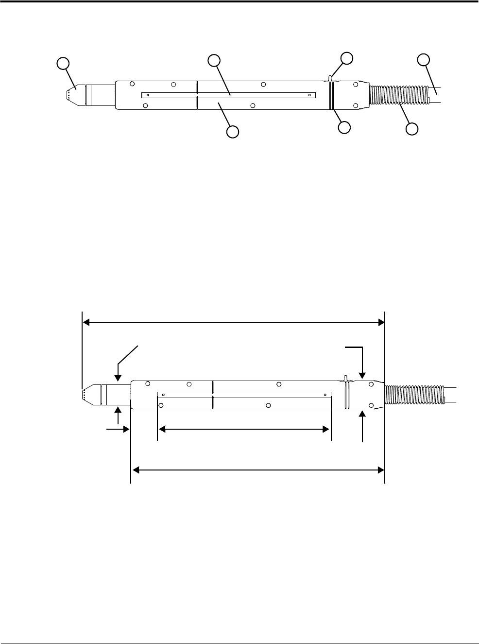
Set Up the Machine Torch
5
92 809240 Operator Manual Powermax45 XP
Machine torch components, dimensions, weights
Components
Dimensions
* This measurement is for the outer dimension of the torch. The height of the outer torch shell is 41 mm
(1.6 inch) when the torch-disable switch is included.
1
2
3
5
6
4
7
1 Consumables
2 32-pitch removable gear rack
3 Torch-disable switch
4 Torch lead
5 Shell
6 Switch position lines
7 Strain relief for torch lead
33 mm
(1.3 inch)
310 mm (12.2 inch)
370 mm (14.6 inch)
35 mm*
(1.4 inch)
212 mm (8.4 inch)
25 mm
(1.0 inch)
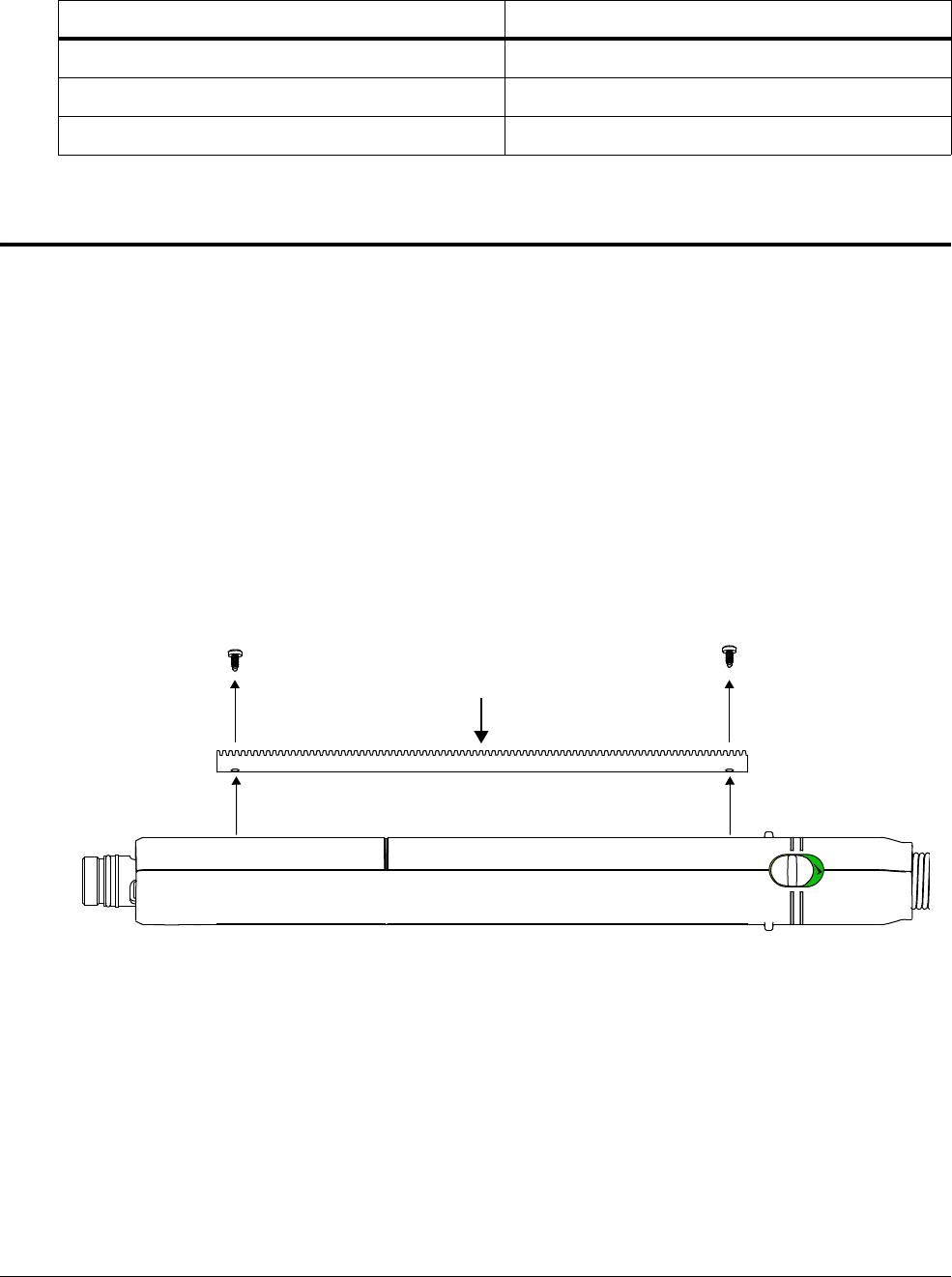
Set Up the Machine Torch
5
Powermax45 XP Operator Manual 809240 93
Weights
Mount the torch
The machine torch can be mounted on a wide variety of X-Y tables, track burners, pipe bevelers, and
other equipment. Install the torch per the table or equipment manufacturer’s instructions.
If your cutting table’s track is large enough for you to route the torch through it without removing the
torch shell, do so and then attach the torch to the lifter per the manufacturer’s instructions.
Remove the gear rack
The gear rack can be mounted on either side of the torch. If you need to remove the gear rack,
remove the 2 screws that secure the rack to the torch shell.
When you install the gear rack, tighten the screws by hand. To avoid
stripping the screws, do not overtighten.
Torch Weig ht
Machine torch with 7.6 m (25 foot) lead 3.2 kg (7.1 pounds)
Machine torch with 10.7 m (35 foot) lead 4.2 kg (9.3 pounds)
Machine torch with 15 m (50 foot) lead 5.8 kg (12.7 pounds)
Gear rack
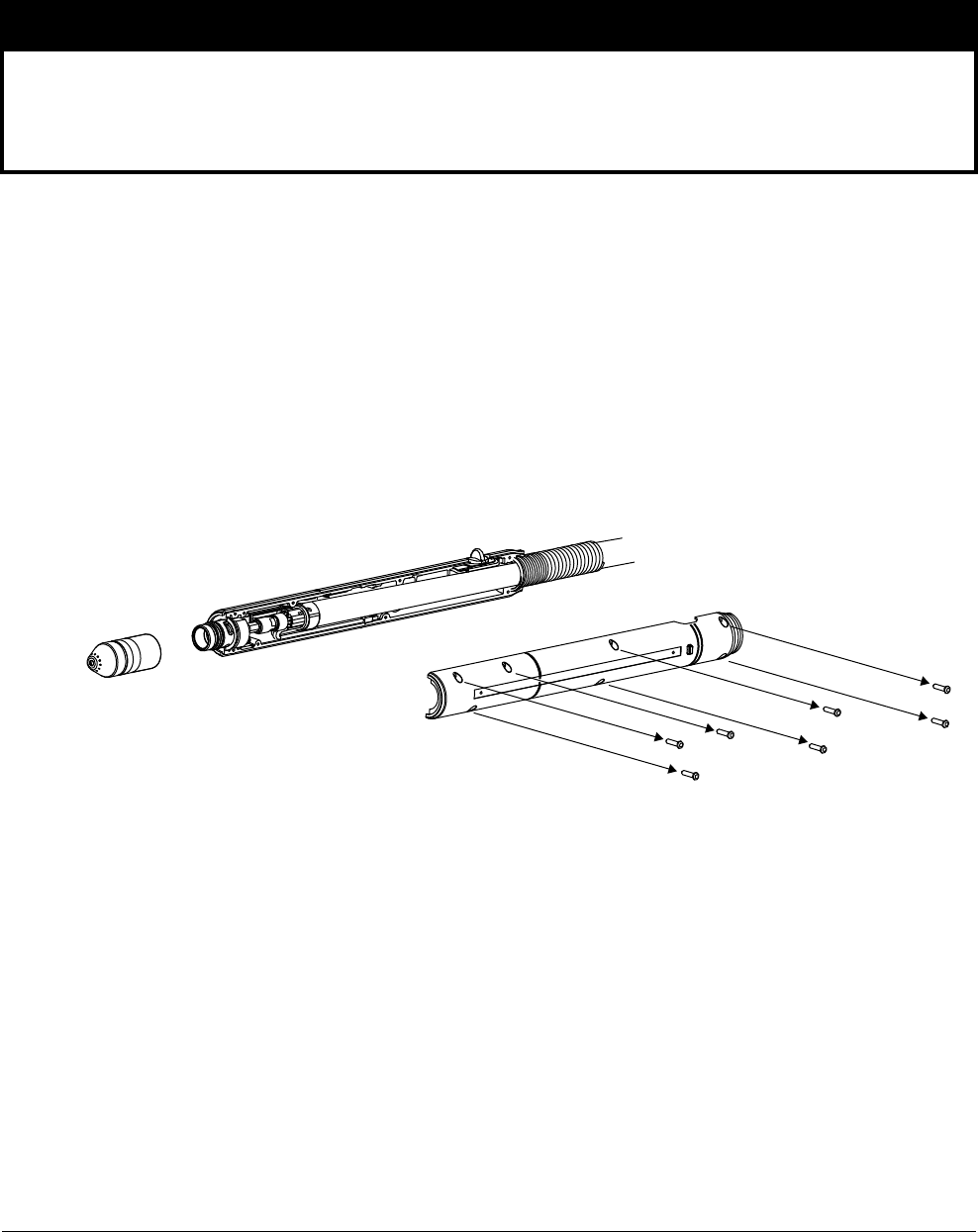
Set Up the Machine Torch
5
94 809240 Operator Manual Powermax45 XP
Disassemble the machine torch
Use the following procedure if you need to disassemble the torch to route the torch through the
cutting table’s track or other mounting system.
1. Disconnect the torch from the plasma power supply.
2. Remove the consumables from the torch.
3. Place the torch on a flat surface with the left side of the shell facing up.
The left side of the shell is the side with the screws.
4. Remove the 7 screws from the torch shell. Set the screws aside.
5. Carefully pry the left side of the shell away from the torch.
NOTICE
While disconnecting and reconnecting the torch parts, do not twist the torch or the lead.
Maintain the same orientation between the torch head and torch lead. Twisting the torch head in
relation to the torch lead can damage the torch wires.
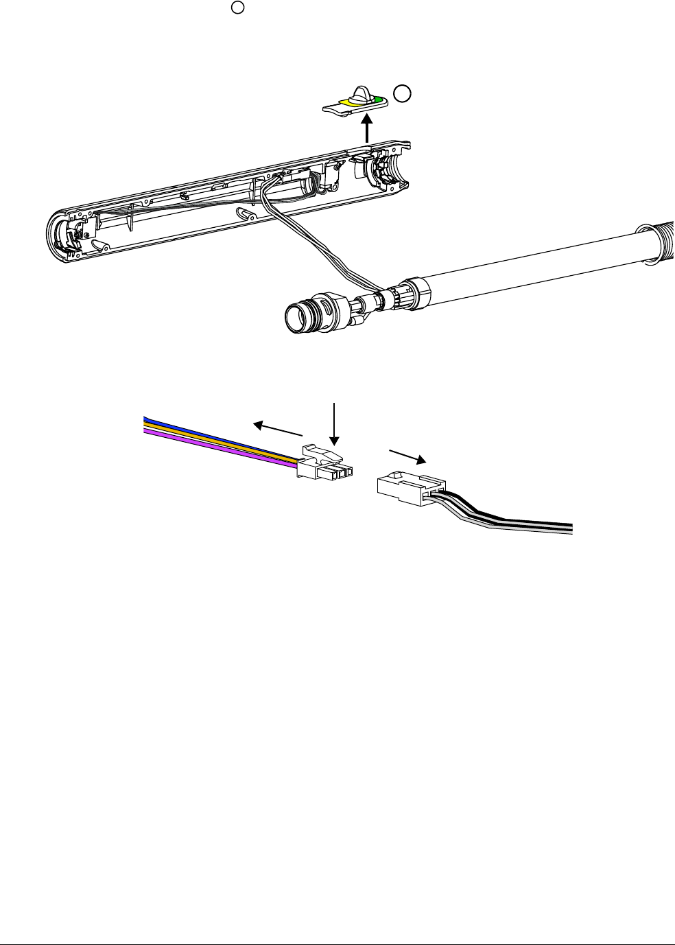
Set Up the Machine Torch
5
Powermax45 XP Operator Manual 809240 95
6. Remove the plastic slider for the torch-disable switch and set it aside.
7. The torch body fits snugly into the right side of the shell. Gently pry the head of the torch body
out and away from the right side of the shell to remove it.
8. Disconnect the wires that sit in the right shell. Press down the tab on the wire connector to pull
the 2 sides apart.
9. You can now route the torch body and the torch lead through the mounting system for the
cutting table.
Slide the strain relief along the torch lead as needed to move it out of the
way as you route the torch lead through the track.
1
1
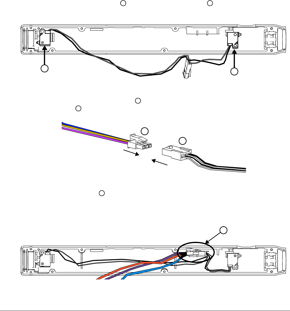
Set Up the Machine Torch
5
96 809240 Operator Manual Powermax45 XP
Assemble the machine torch
If you disassembled the torch to route it through the cutting table’s track or other mounting system,
use the following procedure to reassemble the torch.
While disconnecting and reconnecting the torch parts, do not twist the
torch or the lead. Maintain the same orientation between the torch head
and torch lead. Twisting the torch head in relation to the torch lead can
cause damage to the torch wires.
1. Place the right torch shell on a flat surface.
2. Make sure the cap-sensor switch and the torch-disable switch sit in the right torch shell as
shown. Mounting posts in the torch shell hold each switch in place.
3. Connect the wires from the torch body to the wires from the cap-sensor switch/torch-disable
switch assembly .
4. Place the wire connector on the mounting shelf in the right torch shell as shown.
Route the blue and black wires from the cap-sensor switch and the torch-disable switch outside
of and below the mounting shelf. This helps to prevent the wires from getting pinched and
damaged when the torch is fully assembled.
1
2
1
2
3
4
3
4
5
5
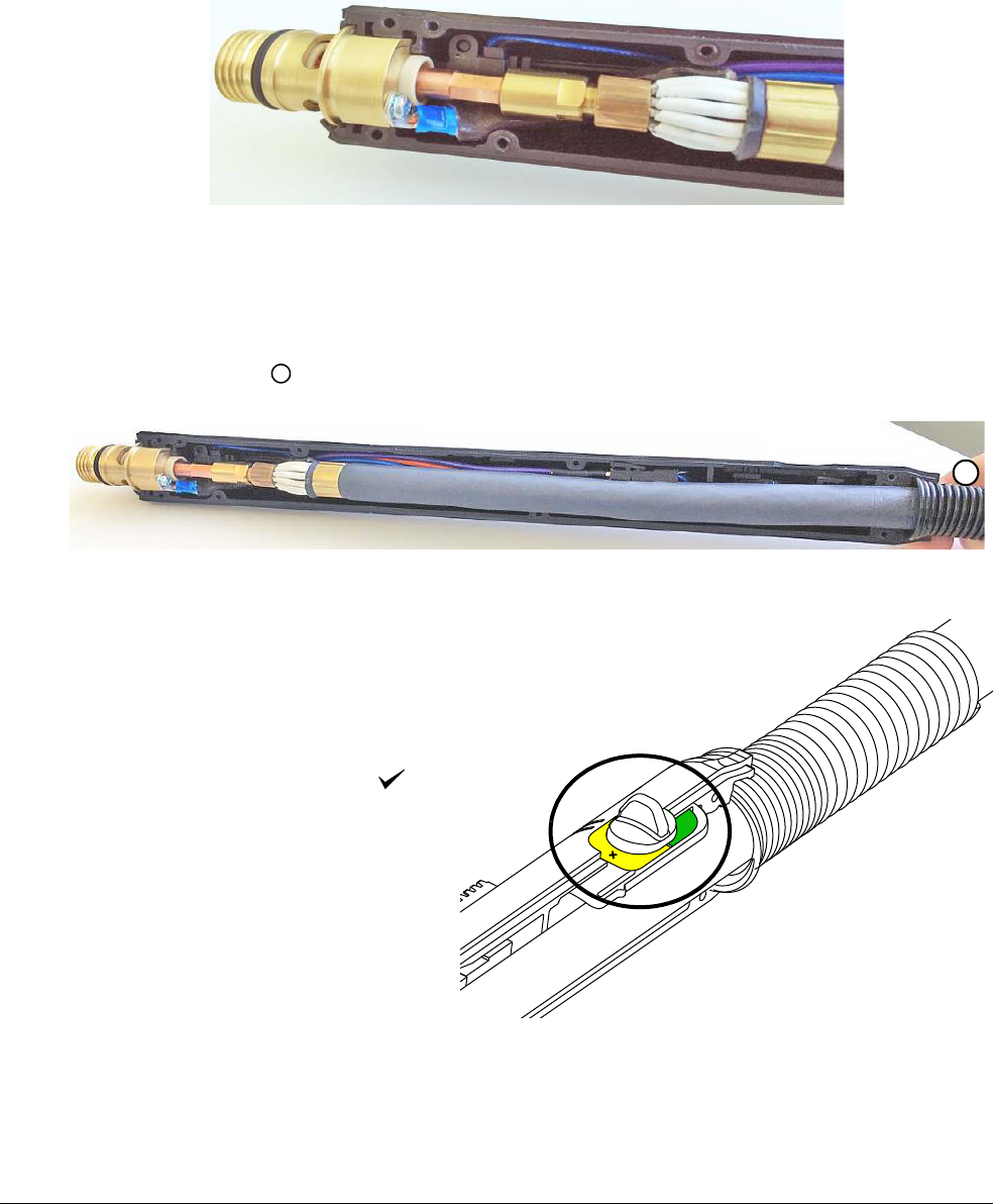
Set Up the Machine Torch
5
Powermax45 XP Operator Manual 809240 97
5. Push the head of the torch body into the right torch shell as shown. Make sure:
The torch shell fits over the flat edges of the torch head. The rounded edge of the torch
head should be facing up.
The wire connector from the previous step remains in place on the mounting shelf. Hold
the wire connector in place as you fit the torch body into the torch shell.
6. Fit the rest of the torch body into the right torch shell as shown. As you do, tuck all of the wires
under the torch body. Do not pinch or crimp the wires. Make sure none of the wires are covering
the screw holes in the torch shell.
7. Fit the strain relief into the base of the right torch shell.
8. Put the plastic slider for the
torch-disable switch into place in the
yellow lock (X) position.
If you try to put the torch back
together with the slider in the
green “ready to fire” ( )
position, you can damage the
torch-disable switch that is
inside the shell behind the
torch body.
6
6
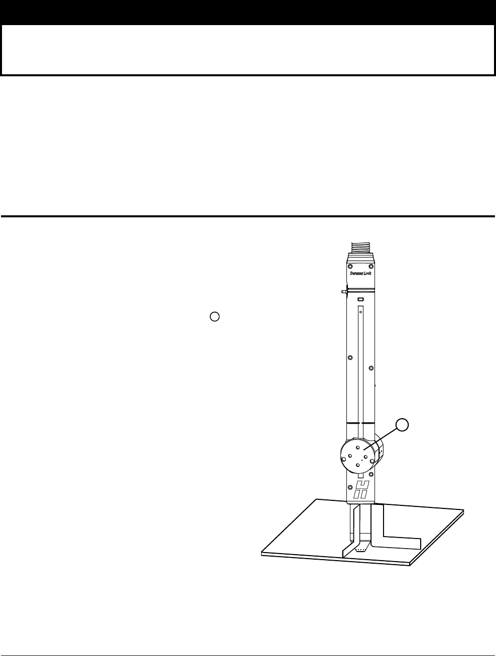
Set Up the Machine Torch
5
98 809240 Operator Manual Powermax45 XP
9. Attach the left torch shell to the right torch shell using the 7 screws. Firmly grasp the torch shells
at the base near the strain relief and hold them together as you install the screws.
10. Examine the torch to make sure no wires are pinched where the torch shells meet.
11 . Install the gear rack on the torch shell.
12. Attach the torch to the lifter per the manufacturer’s instructions.
13. Reinstall the consumables on the torch. See page 48.
Align the torch
Mount the machine torch
perpendicular to the workpiece to
get a vertical cut. Use a square to
align the torch at a 90° angle to
the workpiece.
Position the mounting bracket
lower on the torch to minimize
vibration at the tip of the torch.
Do not overtighten the
mounting bracket. Excessive
pressure from the clamp can
warp or damage the torch shell
over time.
NOTICE
Be careful to avoid pinching the wires between the torch shells. This can damage the wires and
prevent the torch from operating properly.
1
90°
1
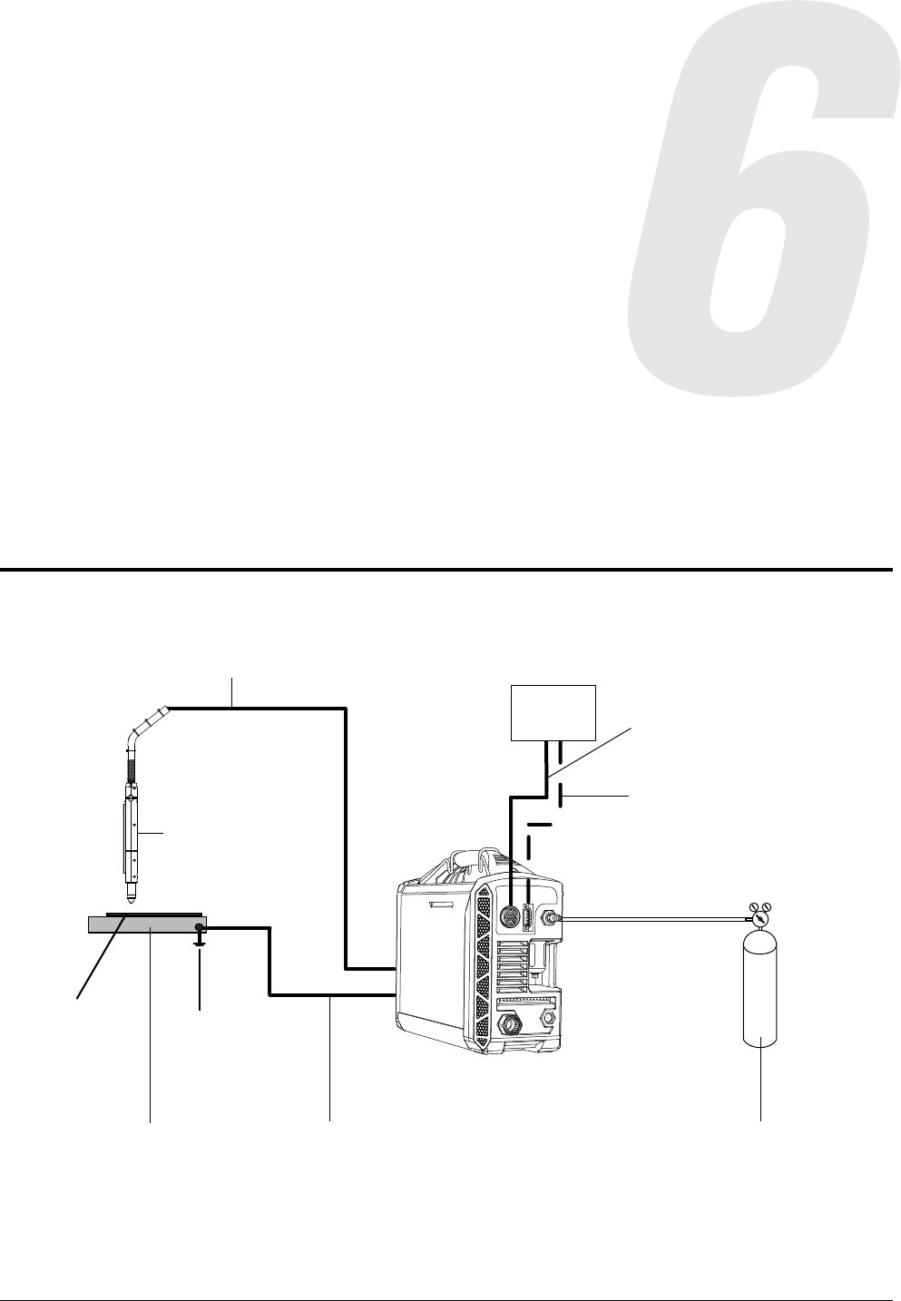
Powermax45 XP Operator Manual 809240 99
Configure Controls for Mechanized Cutting
Machine torch setup overview
Ground
Work table
Workpiece
Machine torch
RS-485 serial cable (optional)
Torch lead
CNC
Machine interface (CPC) cable
Gas supplyWork lead
Configure Controls for Mechanized Cutting
6
100 809240 Operator Manual Powermax45 XP
Set up the plasma system and machine torch for mechanized cutting
1. Attach the work lead from the plasma power supply to the work table.
2. Connect the gas supply to the plasma power supply. See page 37.
Use compressed air to cut mild steel, stainless steel, aluminum, and other conductive
metals.
Use F5 to cut stainless steel. See page 117.
Use argon for marking applications. See page 120.
3. Connect the plasma power supply to your CNC (or other controller) using the machine interface
(CPC) connection.
Your plasma system must be equipped with a factory-installed (or user-installed)
CPC port with internal voltage divider board. See page 102.
A CPC connection is required to fire the torch and to control the signals for arc transfer
and arc voltage.
WARNING
GAS CYLINDERS CAN EXPLODE IF DAMAGED
Gas cylinders contain gas under high pressure. If damaged, a cylinder can explode.
For high pressure regulators, adhere to the manufacturer’s guidelines for safe
installation, operation, and maintenance.
Before plasma cutting with compressed gas, read the safety instructions in the
Safety and Compliance Manual (80669C). Failure to follow safety instructions can
result in personal injury or in damage to equipment.
WARNING
EXPLOSION HAZARD – CUTTING WITH ALUMINUM NEAR WATER
Do not cut aluminum alloys underwater or on a water table unless you can prevent
the accumulation of hydrogen gas. Never cut aluminum-lithium alloys in the
presence of water.
Aluminum can react with water to produce hydrogen, resulting in a potentially
explosive condition that can detonate during plasma cutting operations. Refer to the
Safety and Compliance Manual (80669C) for more information.
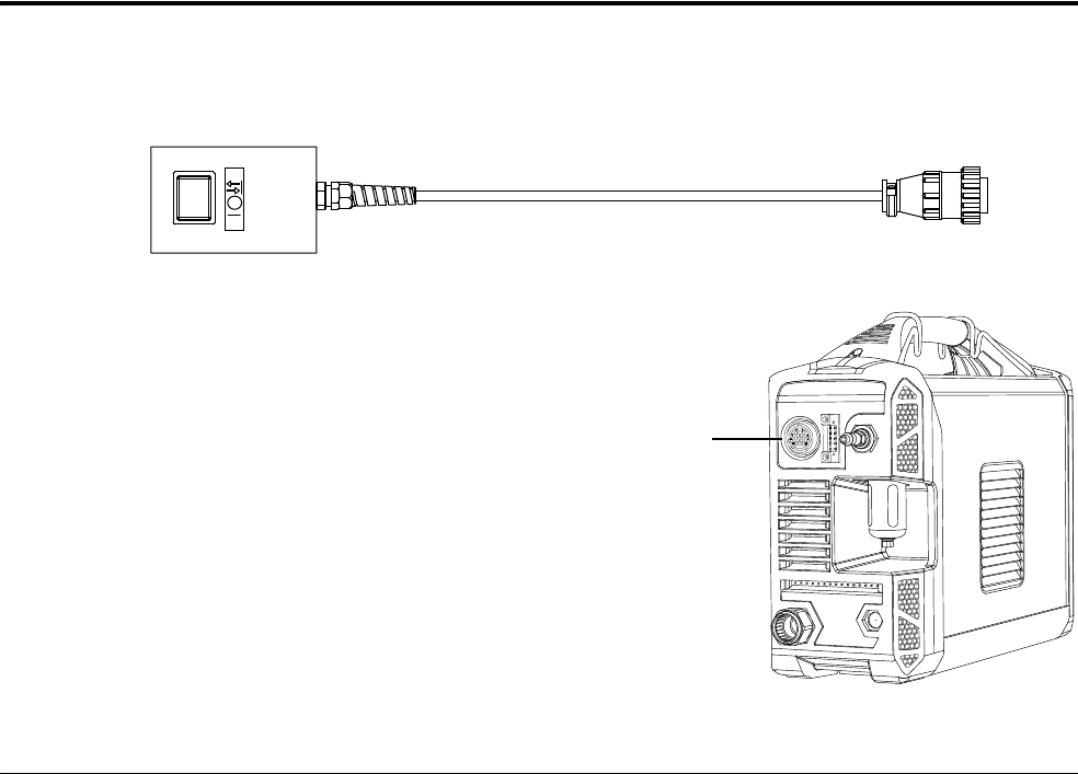
Configure Controls for Mechanized Cutting
6
Powermax45 XP Operator Manual 809240 101
4. Optional: Connect the plasma power supply to your CNC using the RS-485 serial interface
connection.
To use the optional RS-485 serial interface, make sure your plasma system is equipped
with a factory-installed (or user-installed) RS-485 serial interface port. See page 109.
The RS-485 serial interface provides added capabilities for controlling the plasma
system from the CNC, but it cannot be used to fire the torch.
5. Attach the torch to the table or other cutting equipment per the manufacturer’s instructions. See
page 93 for additional information.
6. Install the correct cutting, gouging, or marking consumables for your application:
Cutting and piercing with a machine torch: See Choose the consumables on
page 111.
Gouging: See Gouging processes on page 75.
Marking: See Marking consumables (10 – 25 A) on page 119.
7. Select Cut mode or Gouge/Marking mode on the front panel of the plasma power supply to
match the consumables you installed. See Cutting controls on page 44.
8. Adjust the torch speed and output current (amperage) as needed. See the cut charts starting on
page 129.
Connect the remote-start pendant
Powermax45 XP configurations with a Duramax Lock machine torch can include an optional
remote-start pendant.
The remote-start pendant enables you to
remotely start and stop the machine
torch. For example, use it when you
mount the torch on a simple track burner
or cutting guide that does not have its
own CNC or other controller.
To use the Hypertherm remote-start
pendant, plug it into the CPC port on the
rear of the power supply.
The remote-start pendant is
for use only with a machine
torch. It will not operate if a
hand torch is installed.
CPC port for
remote-start pendant
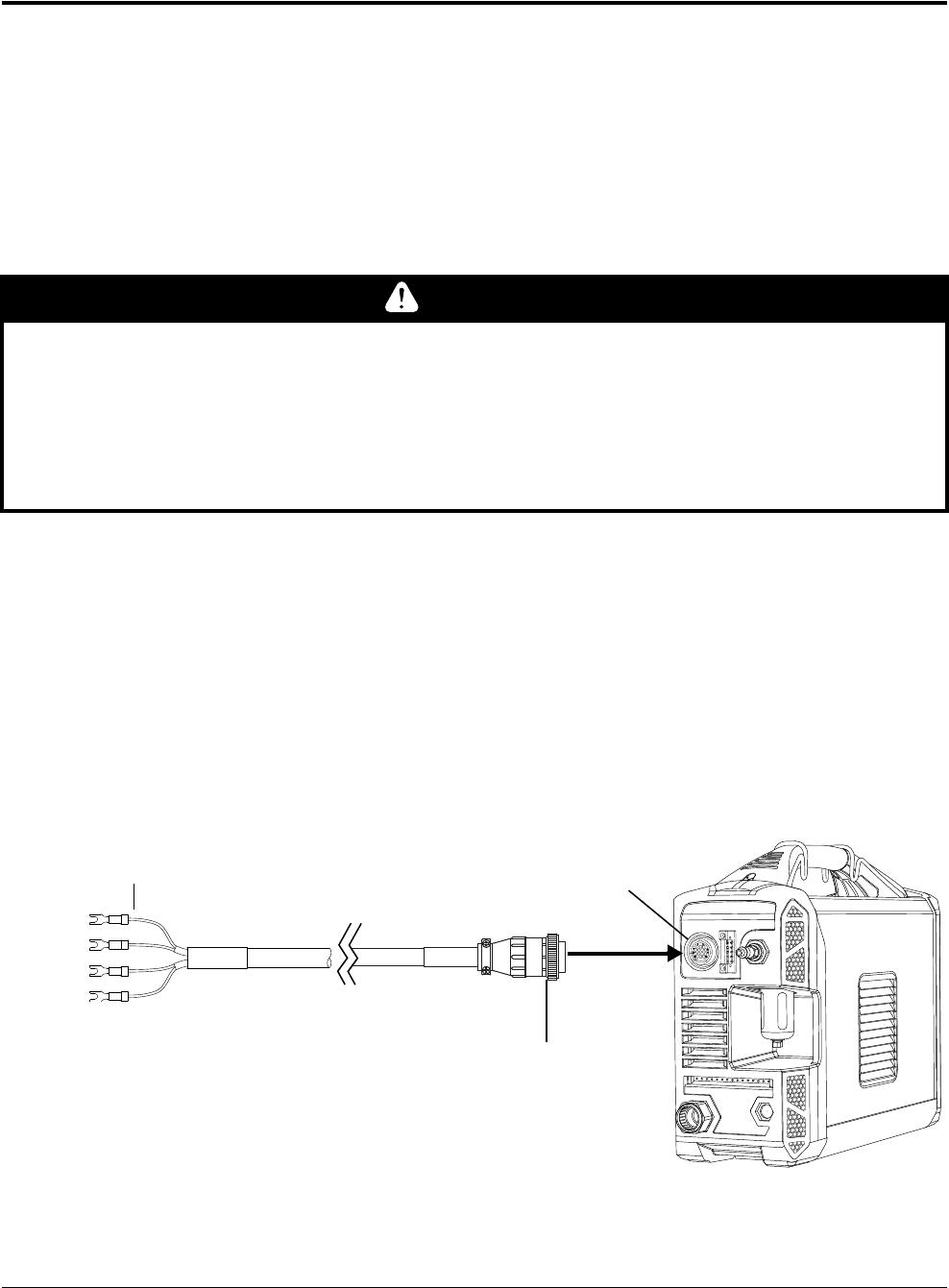
Configure Controls for Mechanized Cutting
6
102 809240 Operator Manual Powermax45 XP
Connect the machine interface cable
To connect a machine interface cable to this system, a factory-installed (or user-installed) CPC port
with 5-position voltage divider must be installed. The voltage divider provides a scaled down arc
voltage of 20:1, 21.1:1, 30:1, 40:1, or 50:1 (maximum output of 16 V). The CPC port on the rear of
the power supply provides access to the scaled down arc voltage and signals for arc transfer and
plasma start.
The factory presets the voltage divider to 50:1. To change the voltage
divider to a different setting, see page 107.
Hypertherm offers several choices of external machine interface cables.
External cables that do not use voltage divider board
To use signals for arc transfer and plasma start only, use one of the following cables:
023206 (7.5 m, 25 feet)
023279 (15 m, 50 feet)
These cables end in wires that are terminated with spade connectors.
CAUTION
The internal voltage divider provides a maximum of 16 V under open circuit conditions. This is an
impedance-protected functional extra low voltage (ELV) output to prevent shock, energy, and fire
under normal conditions at the machine interface receptacle and under single fault conditions
with the machine interface wiring. The voltage divider is not fault tolerant, and ELV outputs do
not comply with safety extra low voltage (SELV) requirements for direct connection to computer
products.
CPC port
CPC connector
Spade connectors
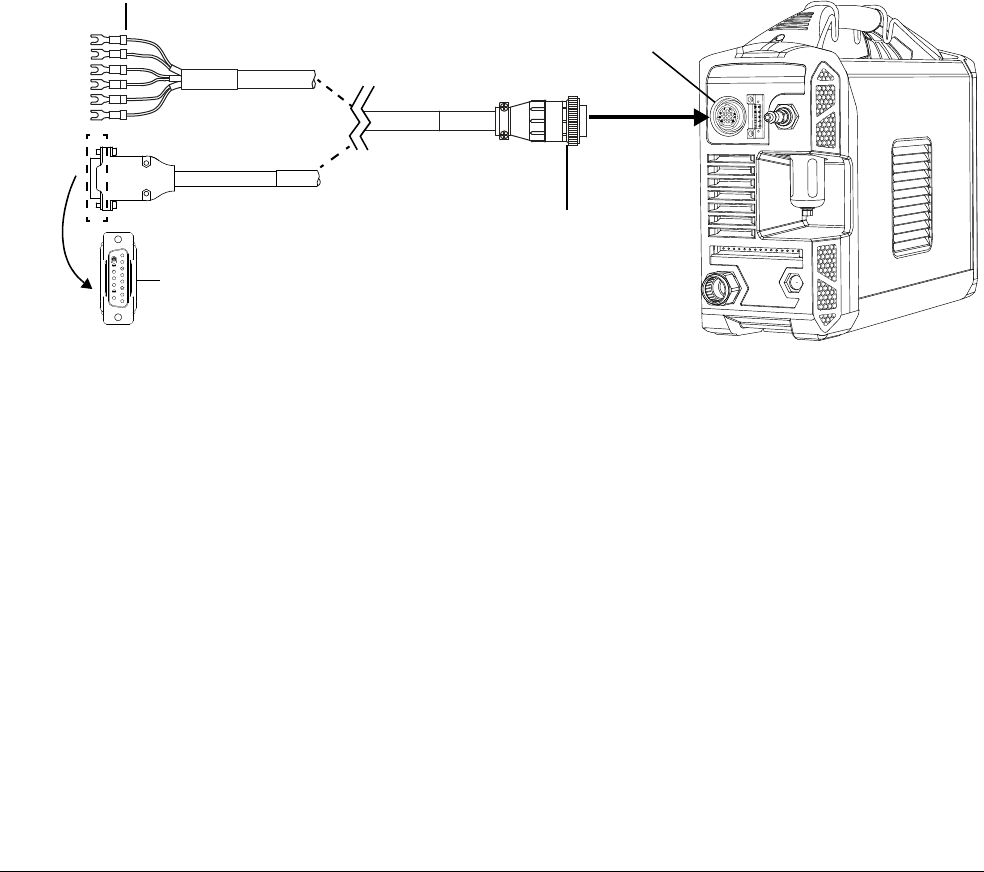
Configure Controls for Mechanized Cutting
6
Powermax45 XP Operator Manual 809240 103
External cables that use voltage divider board
To use the built-in voltage divider that provides a scaled down arc voltage in addition to signals for
arc transfer and plasma start:
For wires terminated with spade connectors, use one of the following cables:
228350 (7.6 m, 25 feet)
228351 (15 m, 50 feet)
For a cable with a D-sub connector, use one of the following cables:
223354 (3.0 m, 10 feet)
223355 (6.1 m, 20 feet)
223048 (7.6 m, 25 feet)
223356 (10.7 m, 35 feet)
123896 (15 m, 50 feet)
CPC port
CPC connector
D-sub connector
Spade connectors
OR
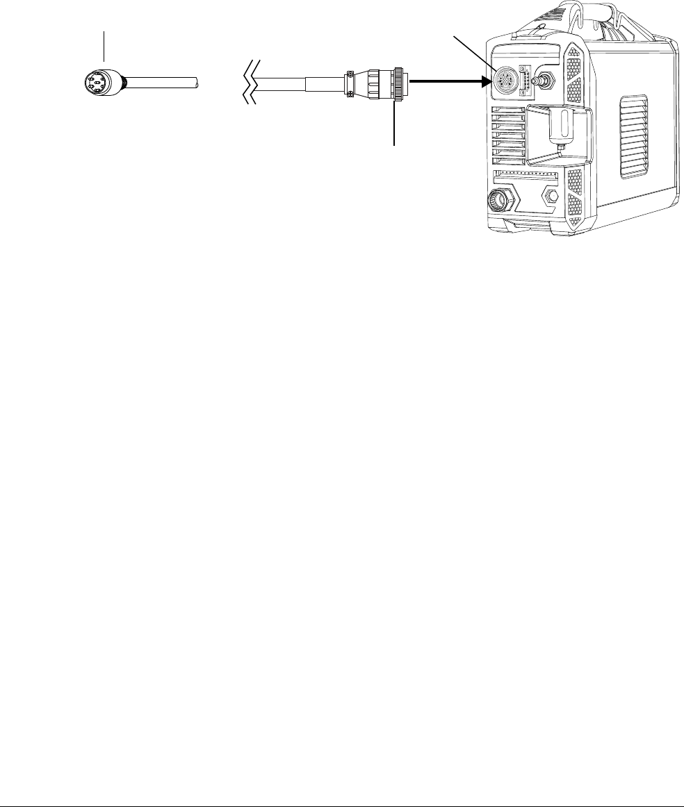
Configure Controls for Mechanized Cutting
6
104 809240 Operator Manual Powermax45 XP
External cables for PlasmaCAM
®
tables
Hypertherm provides machine interface cables designed specifically for use with PlasmaCAM
tables. These cables require the voltage divider board to be set to 21.1:1. See page 107.
223733 (4.6 m, 15 feet)
223734 (6.1 m, 20 feet)
Installation of the machine interface cable
Installation of the machine interface cable must be performed by a qualified service technician. To
install a machine interface cable:
1. Turn O F F (O) the power and disconnect the power cord.
2. Remove the machine interface receptacle’s cover from the rear of the power supply.
3. Connect the Hypertherm machine interface cable to the power supply.
4. If you are using a cable with a D-sub connector on the other end:
a. Plug it into the appropriate pin connector on the torch height controller or CNC.
b. Secure it with the screws on the D-sub connector.
If you are using a cable with wires and spade connectors on the other end:
a. Terminate the machine interface cable inside the electrical enclosure of the torch height
controller or CNC controller. This prevents unauthorized access to the connections after
installation.
b. Verify that the connections are correct and that all live parts are enclosed and protected
before operating the equipment.
The integration of Hypertherm equipment and customer-supplied
equipment including interconnecting cords and cables, if not listed and
certified as a system, is subject to inspection by local authorities at the
final installation site.
CPC port
CPC connector
6-pin DIN connector
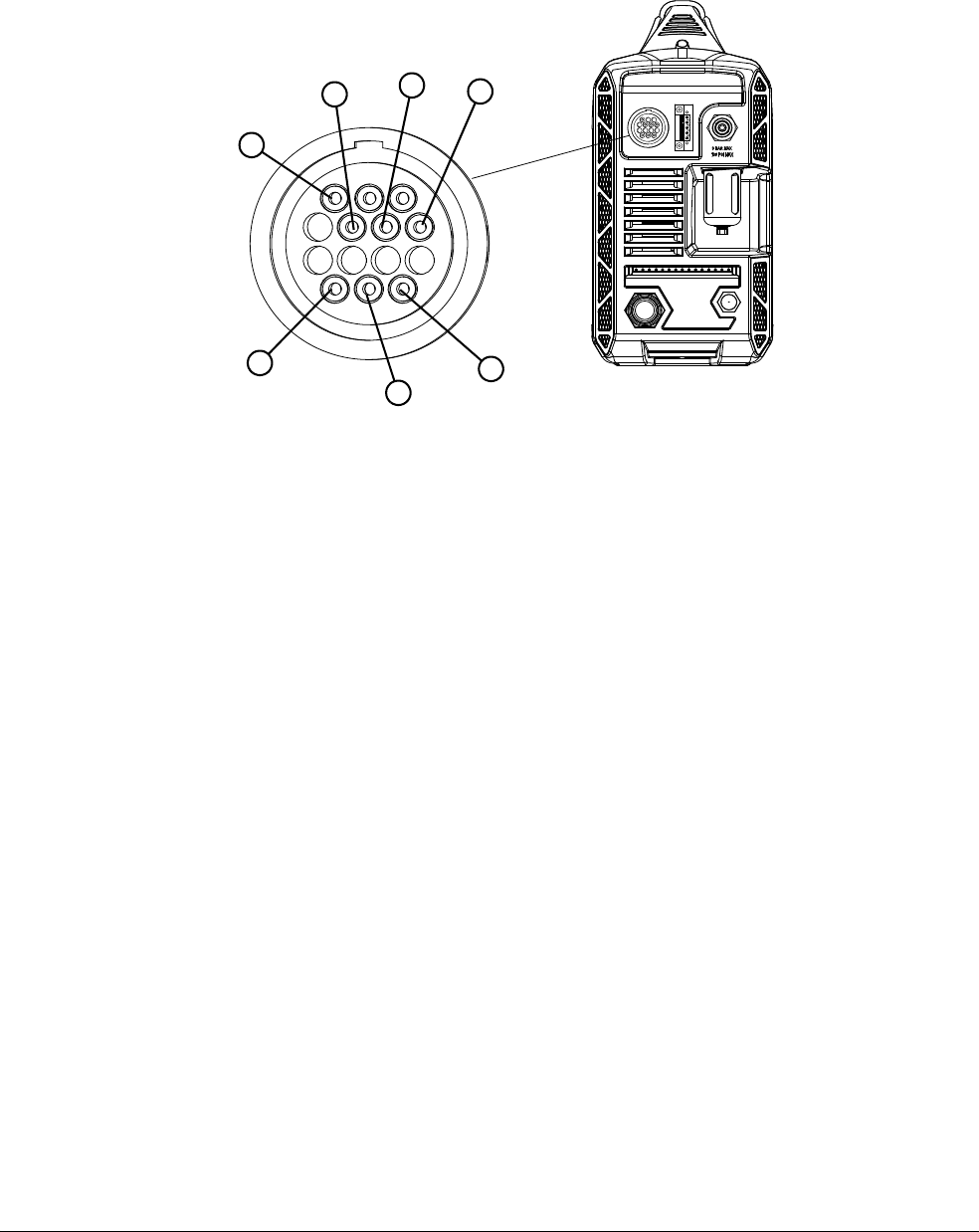
Configure Controls for Mechanized Cutting
6
Powermax45 XP Operator Manual 809240 105
Machine interface pinout
The following figure shows the connector sockets for each type of signal available through the
machine interface cable.
Socket 1 and Socket 2 are wired but not used.
3
5
6
4
13
14
12
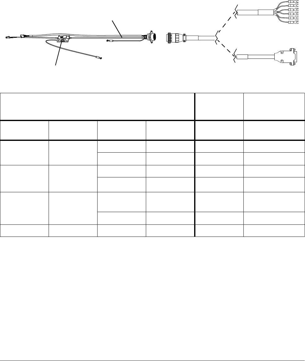
Configure Controls for Mechanized Cutting
6
106 809240 Operator Manual Powermax45 XP
Machine interface signals
Refer to the following table for the cable signal details when connecting the power supply to a torch
height controller or CNC controller with a machine interface cable.
* Normally open. 15 VDC open circuit voltage at START terminals. Requires dry contact closure to activate.
** Normally open. Dry contact closure when the arc transfers. 120 VAC / 1 A maximum at the machine interface
relay.
*** Divided arc signal of 20:1, 21.1:1, 30:1, 40:1, 50:1 (provides a maximum of 16 V).
†
The divided arc signal is a resistive divider of raw arc voltage. This signal is not isolated. To prevent ground
loops, you must supply galvanic isolation.
Powermax internal wires and machine interface receptacle
D-sub
connector
cables
Cables with spade
connectors
Signal Type Wire color
Socket
number
D-sub pin
number
Unterminated wire
color
Start
(start plasma)
Input*
Black 3 10 Green
Red 4 2 Black
Transfer (start
machine
motion)
Output**
White 12 12 Red
Green 14
5Black
Voltage divider Output***,
†
Black (-) 5, 1 (-)
(Electrode)
15 (-) Black (-)
Red (+) 6, 2 (+) (Work) 8 (+) White (+)
Ground Ground Green/yellow 13
D-sub connector
Spade connectors
Voltage divider
Internal wires
OR
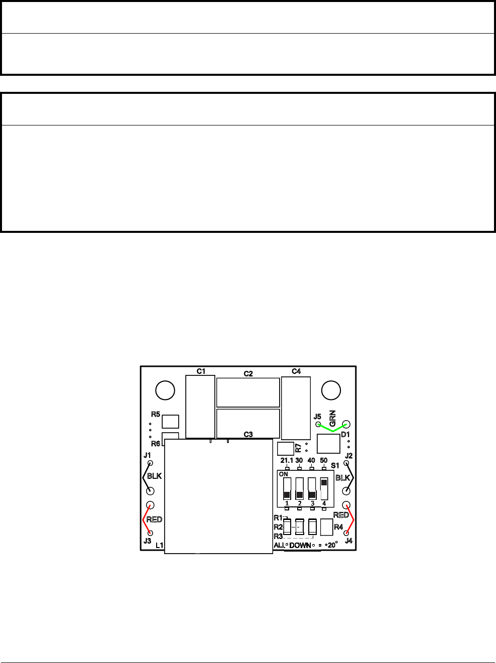
Configure Controls for Mechanized Cutting
6
Powermax45 XP Operator Manual 809240 107
Set the voltage divider PCB
The factory setting on the voltage divider PCB is 50:1. To change the factory preset voltage divider
to a different setting:
1. Turn O F F (O) the power supply and disconnect the power cord.
2. Remove the power supply cover.
Locate the voltage divider DIP switches on the fan side of the power supply.
NOTICE
The voltage divider PCB is a simple resistive divider of raw arc voltage. To prevent ground loops and
electrical interference, you must isolate the divided arc signal.
NOTICE
The factory-installed voltage divider PCB supplies a voltage that is in proportion to the arc voltage. The
DIP switch settings on the voltage divider PCB control the output in open circuit conditions, to a
maximum output of 16 V. This output is an impedance-protected, functional extra-low voltage (ELV)
output. This type of output prevents shock, energy, and fire under normal conditions at the machine
interface receptacle and in single-fault conditions with the machine interface wiring. The voltage divider
PCB is not fault tolerant and ELV outputs do not comply with safety extra-low voltage (SELV)
requirements for direct connection to electrical devices.
L1
X12
R1
R2
R3
R7
R5
R6
R4
C3
C2
C1 C4
L1
BLK
RED
J1
J3
J4
RED
BLK
J2
21.1 30 40 50
GRN
S1
ALL DOWN = 20
D1
J5

Configure Controls for Mechanized Cutting
6
108 809240 Operator Manual Powermax45 XP
3. Set the DIP switches to one of the following settings and replace the power supply cover.
If the Hypertherm 5-position voltage divider does not supply the required voltage for your
application, contact your system integrator for assistance.
The 21.1:1 setting is specifically designed for PlasmaCAM cutting
systems.
20:1 21.1:1 30:1 40:1 50:1
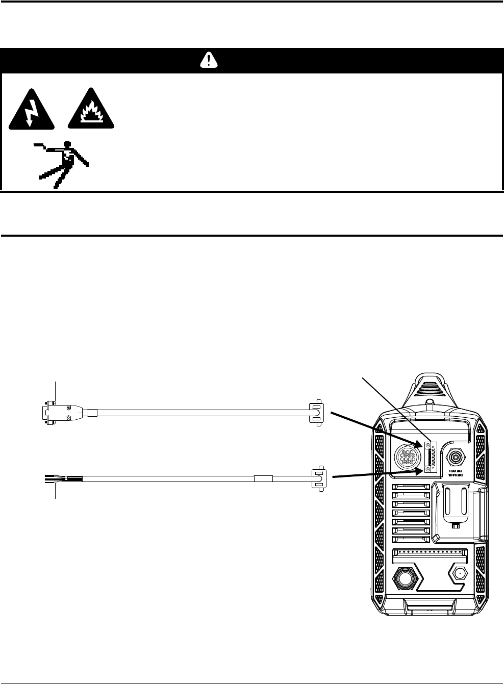
Configure Controls for Mechanized Cutting
6
Powermax45 XP Operator Manual 809240 109
Access raw arc voltage
To access divided raw arc voltage, refer to Field Service Bulletin 809520.
Connect an optional RS-485 serial interface cable
The RS-485 serial interface port on the back of the power supply allows you to connect an external
device to your Powermax. For example, you can remotely operate the Powermax with a
CNC controller.
The Powermax power supply must be equipped with a factory-installed (or user-installed)
RS-485 serial interface port on the rear panel.
WARNING
SHOCK HAZARD, ENERGY HAZARD, AND FIRE HAZARD
Connecting directly to the plasma circuit for access to raw arc voltage
increases the risk of shock hazard, energy hazard, and fire hazard in the
event of a single fault. The output voltage and the output current of the
circuit are specified on the data plate.
D-sub serial connector
OR
Unterminated serial connector
RS-485 serial port
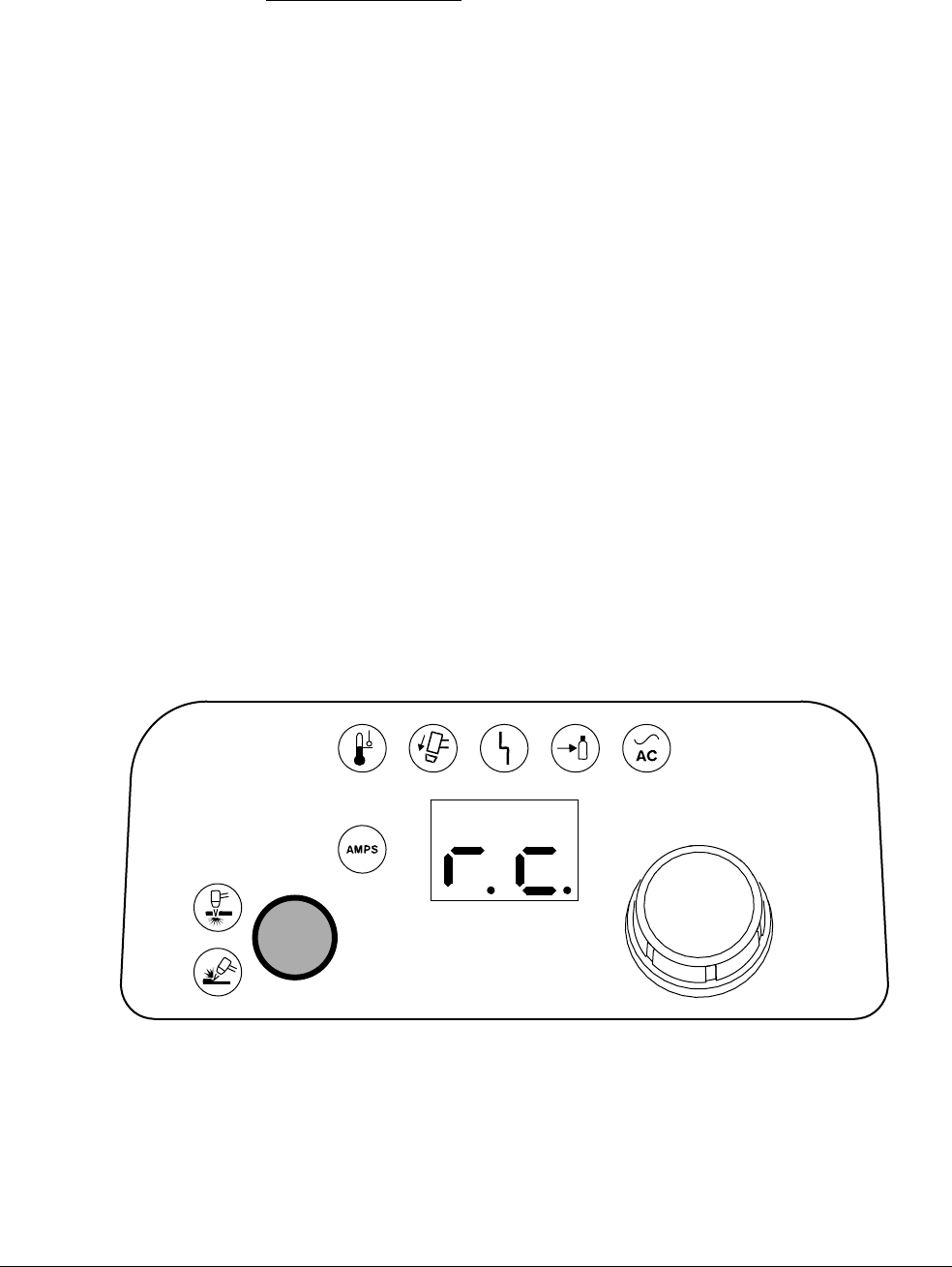
Configure Controls for Mechanized Cutting
6
11 0 809240 Operator Manual Powermax45 XP
If your power supply is not equipped with the RS-485 port, order kit 428654. Follow the installation
instructions in the Powermax45 XP Service Manual (809230), which you can download from the
“Documents library” at www.hypertherm.com
. (Look for the link at the bottom of the page.)
With the RS-485 port installed:
1. Turn O F F (O) the power supply.
2. Connect the RS-485 cable from your external device to the serial port on the back of the
plasma power supply.
External serial port cables
The following external serial cables are available with the specified lengths and connectors:
223236 – RS-485 cable, unterminated, 7.6 m (25 feet)
223237 – RS-485 cable, unterminated, 15 m (50 feet)
223239 – RS-485 cable, 9-pin D-sub connector for Hypertherm controls, 7.6 m (25 feet)
223240 – RS-485 cable, 9-pin D-sub connector for Hypertherm controls, 15 m (50 feet)
Remote mode
When you operate the plasma system remotely using a CNC controller, the 2-digit display on the
front panel shows “r.c.” This indicates that the power supply is being controlled remotely via serial
communications and that all front panel controls are disabled until you exit remote mode.
When the power supply is being remotely controlled, fault LEDs and fault
codes still display as they would otherwise. See page 151.

Powermax45 XP Operator Manual 809240 111
Cut with the Machine Torch
This section provides information to help you:
Choose the correct consumables
Optimize cut quality
Pierce metal
Cut stainless steel with F5 gas
Choose the consumables
Your Duramax Lock machine torch ships with a starter consumable kit that contains a complete set
of shielded consumables plus 1 extra electrode and 1 extra nozzle. Consumables for gouging and
marking are available to order separately.
For details on gouging processes and consumables, see Gouge with the Hand Torch and
Machine Torch on page 75.
For details on the system’s marking capabilities and consumables, see Guidelines for
Marking on page 119.
FlushCut consumables can also be used with the Duramax Lock machine
torch. See FlushCut™ consumables on page 65.
Consumables are shielded or unshielded.
Shielded consumables provide greater protection for the nozzle to minimize damage
caused from slag during piercing. Hypertherm recommends the use of shielded
consumables whenever possible.
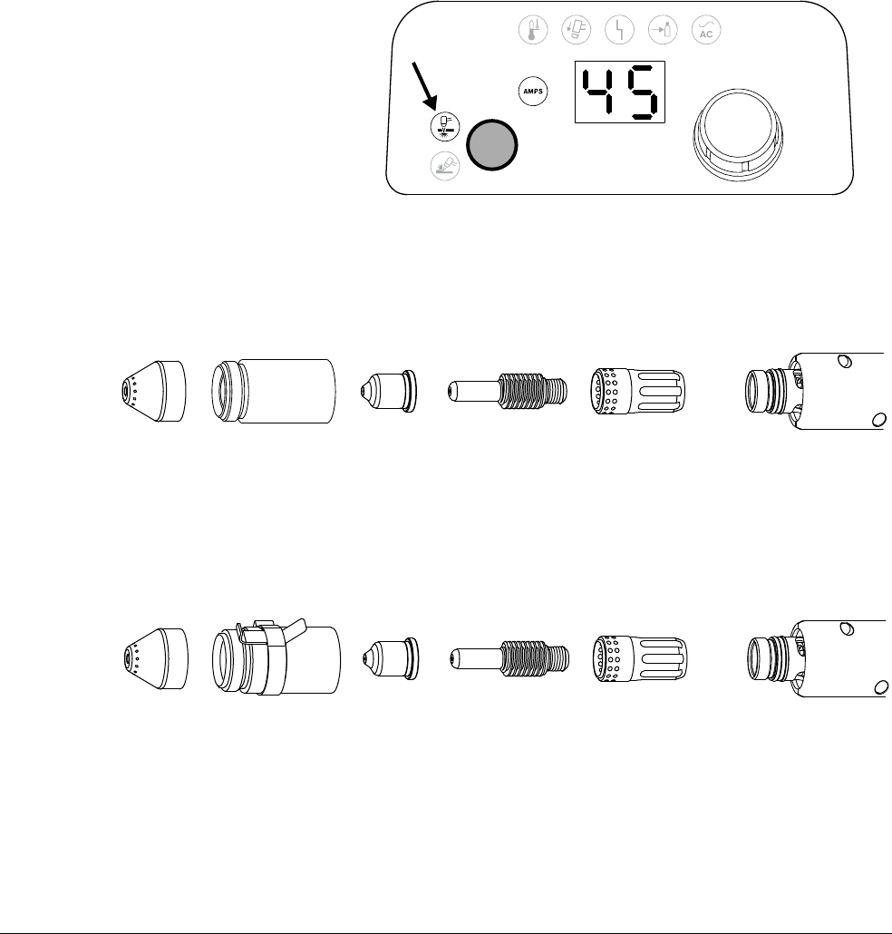
Cut with the Machine Torch
7
112 809240 Operator Manual Powermax45 XP
If you are using unshielded consumables (for example, a deflector instead of a shield), be
careful to maintain the correct torch height in order to avoid damaging the nozzle from slag
or from accidental contact with the workpiece.
Hypertherm does not recommend the use of any other consumables in
the Duramax Lock machine torch except for those listed in this manual.
The use of any other consumables could adversely affect system
performance.
For help installing the consumables onto the torch, see page 48. Do not
use worn or damaged consumables. See Inspect the consumables on
page 165.
When you use the following
shielded and FineCut
consumables, select Cut mode
on the front panel. See page 53.
Mechanized shielded consumables
Mechanized shielded consumables with ohmic retaining cap
220817
Shield
220854
Retaining cap
220941
Nozzle
220857
Swirl ring
220842
Electrode
220817
Shield
220953
Ohmic retaining
cap
220941
Nozzle
220857
Swirl ring
220842
Electrode
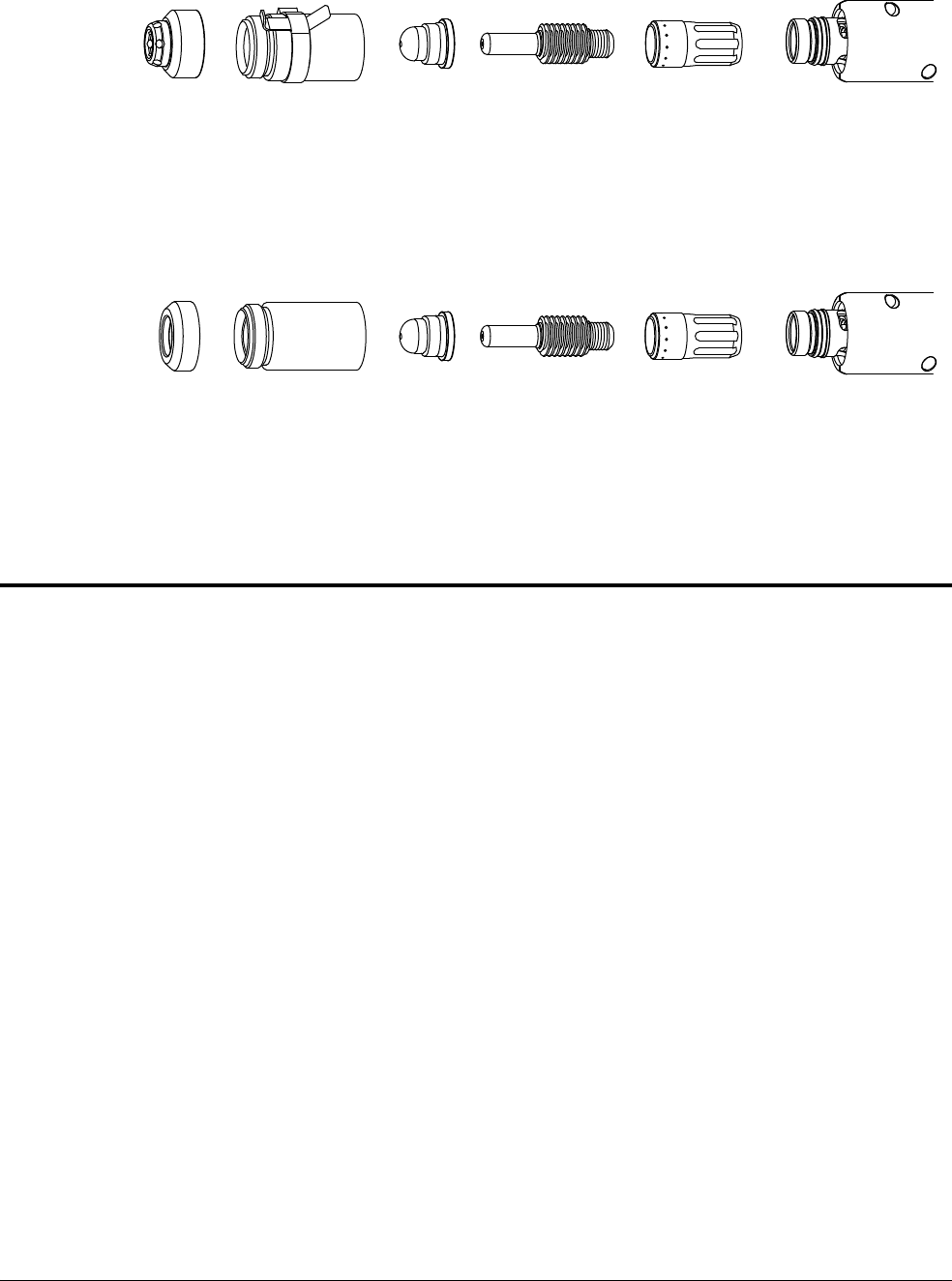
Cut with the Machine Torch
7
Powermax45 XP Operator Manual 809240 11 3
FineCut shielded consumables with ohmic retaining cap
FineCut unshielded consumables
Consumable life
Many factors influence how often you need to change the consumables on your machine torch:
Poor gas supply quality
It is extremely important to maintain a clean, dry gas line. The presence of oil, water,
vapors, and other contaminants in the gas supply can degrade cut quality and
consumable life. See page 38 and page 42.
Cutting and gouging technique
Whenever possible, start cuts from the edge of the workpiece. This helps to extend the
life of the shield and the nozzle.
Maintain a proper pierce height. Refer to the cut charts starting on page 129.
Maintain a proper torch-to-work distance (standoff) when gouging. See page 84.
Shielded versus non-shielded consumables
Non-shielded consumables use a deflector instead of a shield. Non-shielded
consumables generally have a shorter life than shielded consumables.
Thickness of metal being cut
In general, the thicker the metal being cut, the more quickly the consumables become
worn. For best results, do not exceed the thickness specifications for this system. See
page 24.
See page 165 for guidelines on when to replace worn consumables.
220948
Shield
220953
Ohmic retaining
cap
220930
Nozzle
220947
Swirl ring
220842
Electrode
220955
Deflector
220854
Retaining cap
220930
Nozzle
220947
Swirl ring
220842
Electrode
Cut with the Machine Torch
7
114 809240 Operator Manual Powermax45 XP
Expanded metal cutting
Expanded metal has a slotted or mesh pattern. Cutting expanded metal wears out
consumables more quickly because it requires a continuous pilot arc. A pilot arc occurs
when the torch is fired but the plasma arc is not in contact with the workpiece.
Incorrect consumables for output current and mode
To optimize consumable life, make sure the consumables installed on the torch match
the selected mode and output current. For example:
Do not use gouging consumables when the system is set to Cut mode. See
page 53.
Do not set the output current between 26 A and 45 A with the Marking
consumables or the Precision gouging consumables installed.
As a general rule, the consumables last approximately 3 to 5 hours of actual “arc on” time for
mechanized cutting. However, consumable life can vary a lot based on the factors listed above. See
Inspect the consumables on page 165 for information on the signs of wear to look for in
consumables.
Understand and optimize cut quality
Several factors affect cut quality:
Cut angle – The degree of angularity of the cut edge.
Dross – The molten material that solidifies on the top or bottom of the workpiece.
Straightness of the cut surface – The cut surface can be concave or convex.
Cut or bevel angle
A positive cut angle results when more
material is removed from the top of the cut
than from the bottom.
A negative cut angle results when more
material is removed from the bottom of the cut.
The squarest cut angle is on the right side
with respect to the forward motion of the
torch. The left side always has some degree
of cut angle.
1
2
3
Problem Cause Solution
Negative cut angle The torch is too low. Raise the torch; or if you are using a torch height control,
increase the arc voltage.
Square cut
Positive cut angle The torch is too high. Lower the torch; or if you are using a torch height control,
decrease the arc voltage.
1
2
3
Cut with the Machine Torch
7
Powermax45 XP Operator Manual 809240 11 5
To determine whether a cut-angle problem is being caused by the plasma system or the drive
system:
1. Make a test cut.
A square often works well for test cuts. It makes it easier to determine
which side is affected by the cut-angle problem and if that side moved
with the rotation of the torch.
2. Measure the angle of each side of the test cut.
3. Turn the torch 90° in its holder.
4. Repeat steps 1 – 3.
If the angles are the same in both tests:
Verify that mechanical causes have been eliminated.
See Machine torch setup overview on page 99.
Check the torch-to-work distance (especially if the
cut angles are all positive or all negative).
Consider the material being cut. If the metal is magnetized or hardened, you are more likely
to experience cut angle problems.
If the cut angle problem persists, consult with your cutting table manufacturer to verify that your
automatic height control or torch height control is working properly.
Dross
Dross is molten metal created during the cut process that hardens on the bottom of the part. Some
amount of dross will always result when cutting with air plasma. To minimize the amount and type of
dross, adjust your system correctly for your application.
90°
Problem Cause Solution
Excess dross on the top edge of
both pieces of the plate.
• The torch is too low.
• Voltage is too low when
using a torch height control.
• Adjust the torch or adjust the
voltage in small increments
(5 volts or less) until the
dross is reduced.
Low-speed dross on the bottom
of the cut forming a heavy, bubbly
deposit.
• The torch’s cutting speed is
too slow.
• The arc angles ahead.
• Increase the cutting speed.
High-speed dross forms close to
the cut as a thin, linear bead of
solid metal. It is welded to the
bottom of the cut and is difficult
to remove.
• The cutting speed is too fast.
• The arc angles behind.
• Decrease the cutting speed.
• Decrease the torch-to-work
distance.

Cut with the Machine Torch
7
116 809240 Operator Manual Powermax45 XP
Pierce a workpiece using the machine torch
You can start a cut with the machine torch at the edge of the workpiece or by piercing the
workpiece. Refer to the cut charts on page 129 and the piercing guidelines below.
Piercing may result in shorter consumable life than with edge starts.
Pierce delay
The pierce delay is the length of time the triggered torch remains stationary at the pierce height
before the torch starts the cutting motion. The pierce delay must be long enough that the arc can
pierce the material before the torch moves, but not so long that the pierce hole enlarges and causes
the arc to “wander” or extinguish before the torch starts to move. As consumables wear, this delay
time may need to be increased.
Pierce delay times given in the cut charts are based on average delay times throughout the life of the
consumables.
Pierce height
For this system, the pierce height is generally between 1.5 and 4 times the cut height. Refer to the
cut charts starting on page 129 for specific values.
Pierce maximum thickness
When piercing materials close to the maximum thickness for a specific process, consider the
following important factors:
Allow a lead-in distance approximately equal to the thickness of the material being pierced.
For example, 12 mm (1/2 inch) material requires a 12 mm lead-in.
To avoid damage to the shield from the buildup of molten material created by the pierce, do
not allow the torch to descend to cut height until it has cleared the puddle of molten
material.
Different material chemistries can have an adverse effect on the pierce capability of the
system. In particular, high-strength steel with a high manganese or silicon content can
reduce the maximum pierce capability. Hypertherm derives mild steel parameters on
thicknesses of 12 mm (1/2 inch) or less using certified A572 Grade 50 plate.
Cut with the Machine Torch
7
Powermax45 XP Operator Manual 809240 11 7
Cut stainless steel with F5
You can use F5 gas to cut stainless steel with Duramax Lock torches on the Powermax45 XP. When
used with a Powermax system, F5 is recommended only for cutting stainless steel to achieve to the
advantages in cut quality listed below.
See page 139 for a cut chart on cutting stainless steel with F5.
Plasma cutting with F5 produces smooth, shiny cuts with silver edges that are close to the base
color of the metal. F5 avoids the rough, dark finish that typically results with air plasma cutting.
WARNING
TOXIC FUMES CAN CAUSE INJURY OR DEATH
Some metals, including stainless steel, may release toxic fumes when cut. Make sure
your work site has adequate ventilation to ensure that the air quality level meets all
local and national standards and regulations. Refer to the Safety and Compliance
Manual (80669C) for more information.
F5
Air
F5: Advantages F5: Disadvantages F5: Similarities to air
• Smooth, shiny cut edge
• Silver cut edge, similar to the
base color of the metal – does
not leave the rough, dark
surface that air produces
• No oxidation of the cut
surface – the cut steel
maintains its corrosion
resistance
• Ability to use the same
Duramax Lock consumables as
for standard cutting and
gouging with air (includes
CopperPlus™ electrodes)
• Advantages limited to stainless
steel
•Slower cut speeds
• F5 gas is more expensive than
compressed air
• Not recommended for
thicknesses less than 7 mm or
1/4 inch or for use with
FineCut
®
consumables
• Slightly degraded cut quality on
bevel cuts
• Approximately the same
amount of dross. With F5 and
with air, stainless steel dross is
dark in color and can be
challenging to remove.
• Approximately the same gas
pressure requirements

Cut with the Machine Torch
7
118 809240 Operator Manual Powermax45 XP

Powermax45 XP Operator Manual 809240 11 9
Guidelines for Marking
You can use the Marking consumables on the Duramax Lock machine torch to perform marking,
scoring, and dimpling applications on mild steel, stainless steel, and aluminum using air or argon.
For marking cut charts, refer to page 140 and page 141.
The Marking consumables can also be used on the Duramax Lock hand
torches for hand marking applications.
Marking consumables (10 – 25 A)
A maximum output current of 25 A is recommended for marking applications. Using the Marking
consumables at higher amperages can shorten the life of the nozzle. It may also result in deeper
marks than desired and poorer results overall.
420542
Shield
220854
Retaining cap
420415
Nozzle
220842
Electrode
220857
Swirl ring
420542
Shield
220953
Ohmic retaining
cap
420415
Nozzle
220842
Electrode
220857
Swirl ring

Guidelines for Marking
8
120 809240 Operator Manual Powermax45 XP
Process gas: air versus argon
With this system and torch, you can use air or argon for marking applications.
How the system handles postflow for marking
Postflow is gas that flows from the torch in order to cool the consumables after the plasma arc
extinguishes. When you use air (or nitrogen) for marking applications, the duration of postflow is
10 seconds. The system recognizes when argon is being used and decreases postflow from
10 seconds to 3 seconds in order to minimize gas usage. To achieve 3-second postflow:
The system must be set to Gouge/Marking mode.
The output current must be set to 10 – 25 A.
The plasma arc must be sustained for a minimum of 0.5 seconds.
WARNING
GAS CYLINDERS CAN EXPLODE IF DAMAGED
Gas cylinders contain gas under high pressure. If damaged, a cylinder can explode.
For high pressure regulators, adhere to the manufacturer’s guidelines for safe
installation, operation, and maintenance.
Before plasma cutting with compressed gas, read the safety instructions in the
Safety and Compliance Manual (80669C). Failure to follow safety instructions can
result in personal injury or in damage to equipment.
Air Argon
Advantages
•Low cost
• Excellent all around process
• Little or no top-side slag on mild steel
• Low heat input lessens chance of
material deformation
• Excellent high contrast for light scoring
Disadvantages
• High heat input, especially on thin
metal; may cause material deformation
• Mark edges may appear jagged on
aluminum
• More dross and wider marks than with
argon
• Minimum recommended character
height of 8 mm for marks such as
letters and numbers to be legible
• More expensive than air (see How the
system handles postflow for marking
below)
• Heavy scoring leaves top-side slag on
steel
• Minimum recommended character
height of 4 mm for marks such as
letters and numbers to be legible
Guidelines for Marking
8
Powermax45 XP Operator Manual 809240 121
There are 2 scenarios in which postflow is 10 seconds even when argon is used because the
plasma arc is not sustained long enough to produce 3-second postflow:
When the torch fires without transferring the pilot arc to the workpiece
In some dimpling applications where the plasma arc is sustained for less than 0.5 seconds
Types of marking
Marking samples
The following pictures are intended to provide only a rough approximation of the differences
between marking with air versus marking with argon with this system.
Light marking
• Thin, clean, slag-free lines with
little depth
• Marks can be removed or
covered by secondary
operations as desired
Heavy marking / scoring
• Heavier, deeper lines
• Very little slag beside the
intended mark
Dimpling
•Series of round marks
• Dimensions and spacing
controlled by adjusting output
current, gas type, torch height,
and dwell time
Air Argon
Light marking on
mild steel
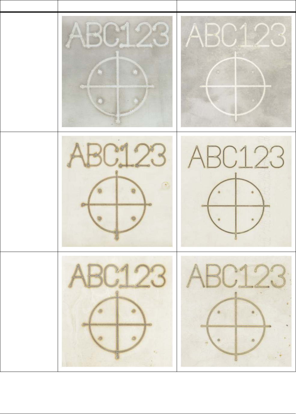
Guidelines for Marking
8
122 809240 Operator Manual Powermax45 XP
Heavy marking on
mild steel
Light marking on
stainless steel
Heavy marking on
stainless steel
Air Argon
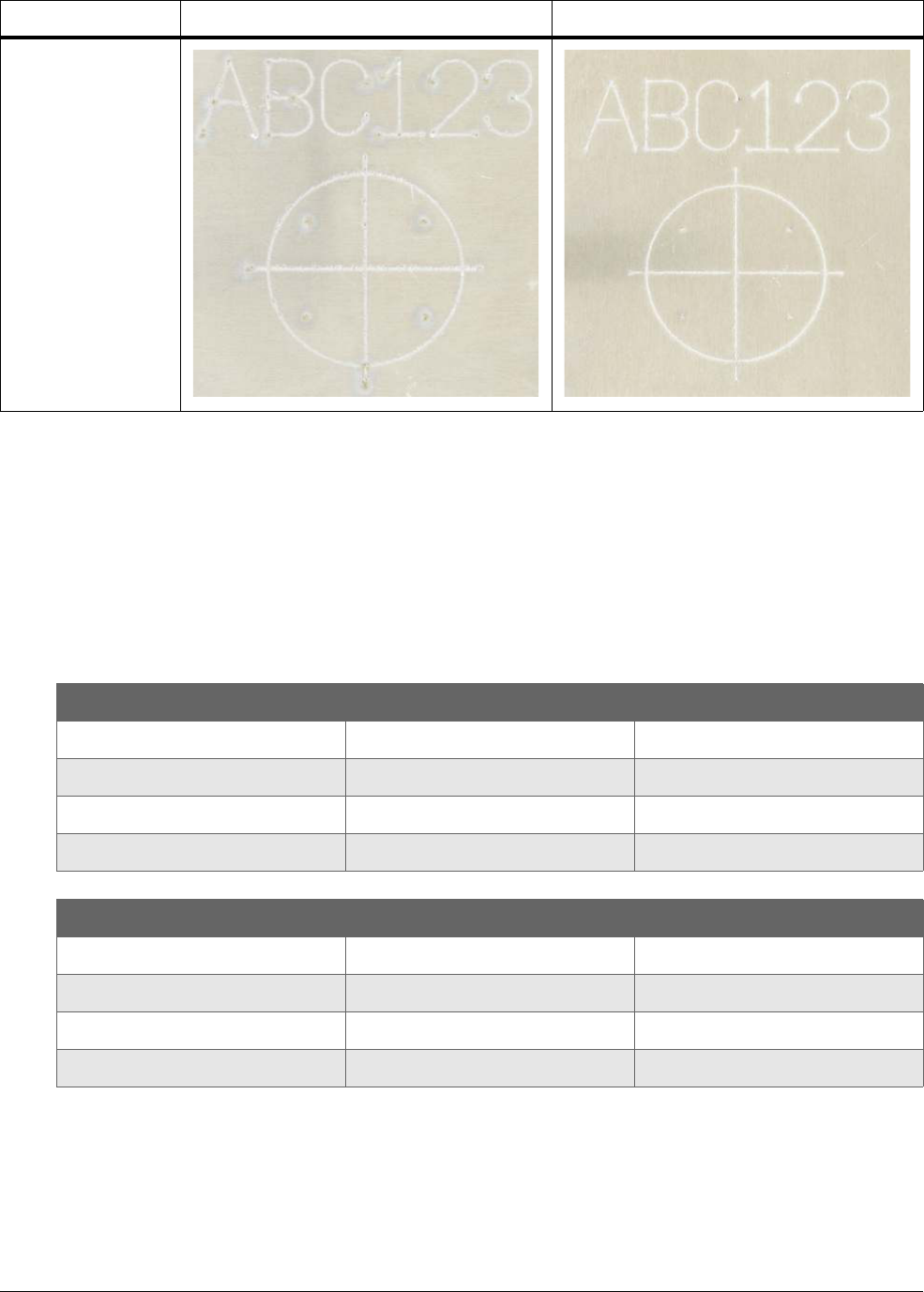
Guidelines for Marking
8
Powermax45 XP Operator Manual 809240 123
Marking, scoring, and dimpling profiles
The following tables show typical width and depth profiles for light marking, heavy marking and
scoring, and dimpling on mild steel.
The width and depth of the marks change as you adjust the output
current, gas type, torch standoff, and marking speed (or dwell time for
dimpling).
Light marking on
aluminum
Air Argon
Light marking
Air Argon
Width 2.79 mm (0.11 inch) 1.22 mm (0.048 inch)
Depth Less than 0.02 mm (0.001 inch) Less than 0.02 mm (0.001 inch)
Travel speed 2.5 m/min (100 in/min) 3.2 m/min (125 in/min)
Heavy marking / Scoring
Air Argon
Width 2.79 mm (0.11 inch) 1.22 mm (0.048 inch)
Depth 0.09 mm (0.0035 inch) Less than 0.02 mm (0.001 inch)
Travel speed 2.5 m/min (100 in/min) 3.2 m/min (125 in/min)

Guidelines for Marking
8
124 809240 Operator Manual Powermax45 XP
Marking process guidelines
Before you begin marking, scoring, or dimpling:
Choose a process gas: air or argon.
Set up your machine torch and table. See Machine torch setup overview on page 99.
Install the Marking consumables.
Set the plasma power supply to
Gouge/Marking mode. See
page 53.
Adjust the torch speed and
power supply output current
(amperage) for your marking or
dimpling job. See the cut charts
starting on page 140.
Set the output current between
10 A and 25 A. Do not exceed
25 A for marking applications.
Additional considerations:
The power supply adjusts gas pressure for you automatically. Hypertherm recommends
using these auto-gas settings for marking.
Hypertherm strongly recommends that you use the Marking consumables with the power
supply set to Gouge/Marking mode and the output current set to 10 – 25 A. These settings
and consumables were designed specifically for marking applications.
This system requires different consumables for marking and for regular cutting. Make sure
you have the correct consumables installed if you switch between marking and cutting jobs.
See page 111 for cutting consumable part numbers.
You can vary the depth and width of marks by varying torch speed, output current, and torch
height.
You may need to try different cornering methods to optimize 90° corners for your CNC and
table. See Cornering guidelines below.
Dimpling
Air Argon
Width 1.98 mm (0.078 inch) 0.99 mm (0.039 inch)
Depth 0.25 mm (0.01 inch) Less than 0.02 mm (0.001 inch)
Dwell time* 50 milliseconds 200 milliseconds
* The dwell time is the period of time that the torch fires at one spot on the workpiece to form a dimple. The
longer the dwell time, the deeper the dimple that will form. Dwell times vary between CNC and table
configurations. You may need to adjust your CNC/table setup accordingly.
Make sure the Gouge/Marking Mode LED is illuminated.
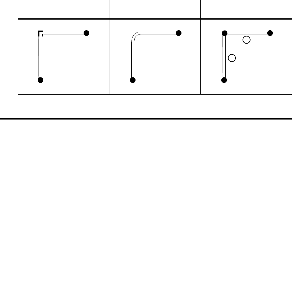
Guidelines for Marking
8
Powermax45 XP Operator Manual 809240 125
Cornering guidelines
Reduce both output current and marking speed for the entire marking operation.
Depending on the capabilities of your cutting table and CNC, you may need to try different
cornering methods to achieve the best possible results on 90° corners.
On many tables, it can be difficult to achieve a clean 90° corner. It requires the torch to
come to a complete stop for some length of time, which can result in a corner that is
wider and deeper than desired.
The rounded corner method shown below is recommended for most table/CNC
configurations. This method does not require the torch to come to a complete stop in
the corner.
If a sharper 90° corner is necessary, you can try the 2-step operation shown below.
However, this method does leave dimples at the “start” and “stop” points.
Marking troubleshooting tips
Factors that affect marking width, depth, and quality include:
Process gas – see the comparison of argon to air on page 120
Material type (mild steel, stainless steel, or aluminum)
Material thickness and surface finish
Plasma power supply output current (amperage)
Torch marking/dimpling speed
Torch standoff
Characteristics of the cutting table and CNC, such as how they handle delays,
accelerations, and decelerations
Gas pressure, if you manually adjusted the pressure to be outside the recommended range
automatically set by the system – see page 56
To optimize your marking or dimpling process and results, use the troubleshooting tips on page 126
and the cut charts starting on page 140.
90° corner – difficult to achieve
on many tables
Recommended method for
most tables/CNCs
Alternate 2-step operation
Start
Stop
Start
Start
Stop
1
2

Guidelines for Marking
8
126 809240 Operator Manual Powermax45 XP
Common marking problems and solutions
For marking applications, always make sure:
The Marking consumables are installed.
The power supply is set to Gouge/Marking mode, and the output current is set between
10 – 25 A.
Many common marking issues can be resolved by installing new consumables in the torch. Do not
use worn or damaged consumables. See page 165.
Problem Solution
The arc goes out during
marking.
• Make sure that the torch-to-work distance (standoff) is not too high.
• Change worn or damaged consumables. See page 165.
The dimple diameter is
wrong.
• For a larger diameter dimple, increase the output current.
• For a smaller diameter dimple, decrease the output current.
• Adjust the torch-to-work distance (standoff).
• Change worn or damaged consumables. See page 165.
The dimple depth is wrong. • For a deeper dimple, increase the dwell time.
• For a shallower dimple, decrease the dwell time (if possible).
• Adjust the torch-to-work distance (standoff).
The mark is too wide or too
deep.
• Decrease the output current.
• Increase the marking speed.
• Inspect the consumables, especially the center hole of the nozzle. Change
worn or damaged consumables. See page 165.
The mark is too narrow or
too shallow.
• Change worn or damaged consumables. See page 165.
• Increase the output current.
• Decrease the marking speed.
• Decrease the torch height.
The beginning of the mark
is too large.
• If the delay time between when the CNC receives the machine motion signal
and when the machine motion actually occurs is significant, piercing may
occur. If possible, decrease the delay time to 0 (zero).
• Check the table parameters, especially the acceleration parameter. It may need
to be increased.
• Decrease the output current to reduce the size of the dimple at the beginning
of the mark. The marking speed may also need to be adjusted for the lower
output current.
• Check the torch-to-work distance (standoff) to make sure there is a good, fast
transfer of the plasma arc to the workpiece.
The end of the mark is too
large.
• Check the cutting table parameters. If possible, increase the deceleration
parameter.

Guidelines for Marking
8
Powermax45 XP Operator Manual 809240 127
Figure 1 – Recommended minimum mark heights
The mark becomes too
deep and too wide during
cornering.
• You may need to try a different method for cornering. See page 125.
Marks such as letters,
numbers, and other
symbols are not legible.
• Make the marks larger. If you use air, the minimum recommended height is
8 mm for marks such as letters and numbers. If you use argon, the minimum
recommended height is 4 mm for marks such as letters and numbers. See
Figure 1.
Problem Solution
Air: Minimum height 8mm
Argon: Minimum height 4mm

Guidelines for Marking
8
128 809240 Operator Manual Powermax45 XP
Powermax45 XP Operator Manual 809240 129
Cut Charts and Marking Charts
WARNING
EXPLOSION HAZARD – CUTTING WITH ALUMINUM NEAR WATER
Do not cut aluminum alloys underwater or on a water table unless you can prevent
the accumulation of hydrogen gas. Never cut aluminum-lithium alloys in the
presence of water.
Aluminum can react with water to produce hydrogen, resulting in a potentially
explosive condition that can detonate during plasma cutting operations. Refer to the
Safety and Compliance Manual (80669C) for more information.
WARNING
EXPLOSION HAZARD – CUTTING WITH FUEL GASES
Do not use combustible fuel gases or oxidizing gases with Powermax systems.
These gases can result in explosive conditions during plasma cutting operations.
WARNING
TOXIC FUMES CAN CAUSE INJURY OR DEATH
Some metals, including stainless steel, may release toxic fumes when cut. Make sure
your work site has adequate ventilation to ensure that the air quality level meets all
local and national standards and regulations. Refer to the Safety and Compliance
Manual (80669C) for more information.

Cut Charts and Marking Charts
9
130 809240 Operator Manual Powermax45 XP
Using the cut charts
The cut charts in this section are intended to provide a good starting point. Adjust the variables in the cut
charts as needed to achieve optimal results for your cutting equipment and environment.
Cut charts are provided for each set of mechanized cutting and marking consumables. A consumable
diagram with part numbers precedes each cut chart.
Cut charts are included for:
Cutting mild steel, stainless steel, and aluminum at 45 A with air using shielded consumables
Cutting mild steel and stainless steel with air using FineCut consumables
Cutting stainless steel at 45 A with F5 using shielded consumables
Marking and dimpling at 10 – 25 A with air and argon using Marking consumables
Each cut chart may contain the following information:
Amperage setting – The amperage setting at the top of the page applies to all the settings given
on that page. In FineCut charts, the amperage setting for each thickness is included in the cut
chart.
Material Thickness – Thickness of the workpiece (metal plate being cut).
Torch-to-Work Distance – For shielded consumables, the distance between the shield and the
workpiece during cutting. For unshielded consumables, the distance between the nozzle and the
workpiece during cutting. This is also known as cut height.
Initial Pierce Height – Distance between the shield (shielded) or the nozzle (unshielded) and the
workpiece when the torch is fired, prior to descending to the cut height. In marking charts, this is
referred to as Initial Marking Height.
Pierce Delay Time – Length of time the triggered torch remains stationary at the pierce height
before the torch starts the cutting motion. In marking charts, this is referred to as Delay Time.
Best Quality Settings (cut speed and voltage) – Settings that provide the starting point for
finding the best cut quality (best angle, least dross, best cut-surface finish). Adjust the speed for
your application and table to obtain the desired result.
Production Settings (cut speed and voltage) – 70% to 80% of the maximum speed ratings.
These speeds result in the greatest number of cut parts, but not necessarily the best possible cut
quality.
The arc voltage increases as the consumables wear, so the voltage setting may
need to be increased to maintain the correct torch-to-work distance. Some
CNCs monitor the arc voltage and adjust the torch lifter automatically.
Kerf Width – Width of material removed by the cutting process. The kerf widths were obtained
with the “Best Quality” settings and are for reference only. Differences between installations and
material composition may cause actual results to vary from those shown in the tables.
Width and Depth – The marking and dimpling cut charts list the profile dimensions of the mark or
dimple.

Cut Charts and Marking Charts
9
Powermax45 XP Operator Manual 809240 131
Each cut chart lists hot and cold gas flow rates.
Hot flow rate – Plasma is on, the system is operating at running current, and the system is in a
steady state at the default system pressure (cutflow, or automatic mode).
Cold flow rate – Plasma is off and the system is in a steady state with gas flowing through the
torch at the default system pressure (postflow).
Hypertherm collected the cut chart data under laboratory test conditions using
new consumables.
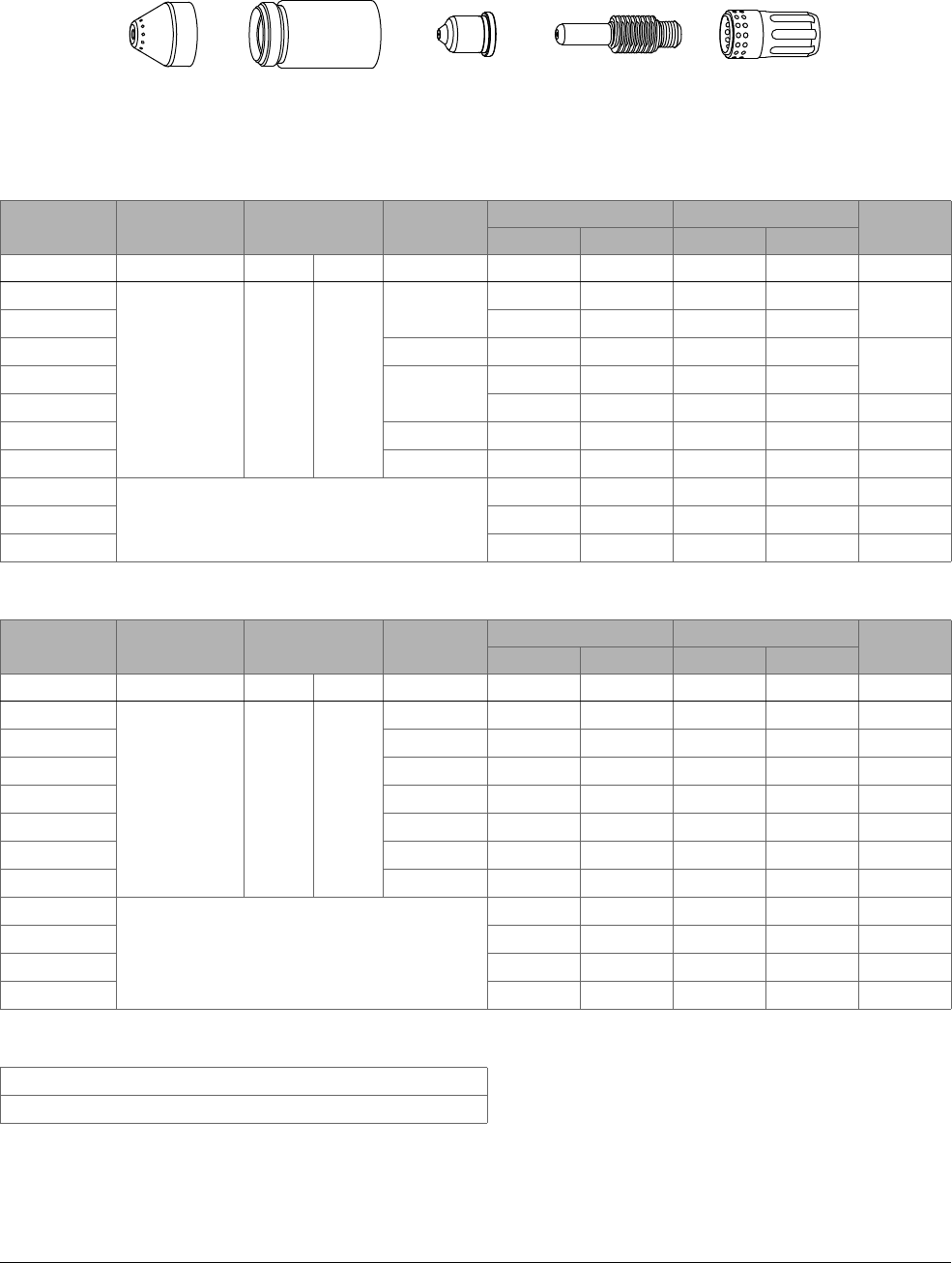
Cut Charts and Marking Charts
9
132 809240 Operator Manual Powermax45 XP
Mild Steel – 45 A – Air – Shielded
Metric
Material
Thickness
Torch-to-Work
Distance
Initial Pierce Height
Pierce
Delay Time
Best Quality Settings Production Settings
Kerf Width
Cut Speed Voltage Cut Speed Voltage
mm mm mm % seconds mm/min volts mm/min volts mm
2
1.5 3.8 250
0.2
5560 128 7910 125
1.4
3 3960 128 5590 128
4 0.4 2800 128 3960 128
1.5
6
0.6
1430 130 2110 127
8 1020 133 1385 130 1.7
10 0.8 780 136 920 134 1.8
12 1 540 140 690 138 1.9
16
Edge Start
310 146 400 141 2.1
20 170 152 240 147 2.3
25 110 157 145 154 3
English
Material
Thickness
Torch-to-Work
Distance
Initial Pierce Height
Pierce
Delay Time
Best Quality Settings Production Settings
Kerf Width
Cut Speed Voltage Cut Speed Voltage
inches inches inches % seconds in/min volts in/min volts inches
16 GA
0.06 0.15 250
0.1 249 128 320 125 0.053
14 GA 0.2 225 128 320 125 0.054
10 GA 0.4 129 128 181 128 0.057
3/16 0.5 85 129 122 127 0.059
1/4 0.6 48 130 72 127 0.061
3/8 0.8 33 136 38 133 0.069
1/2 1 18 141 24 139 0.077
5/8
Edge Start
13 146 16 141 0.082
3/4 7 151 10 145 0.086
7/8 6 154 7 151 0.103
1 4 157 6 154 0.119
Gas flow rate – slpm / scfh
151 / 320 Hot (cutflow)
184 / 390 Cold (postflow)
220817 220854
(220953 for
ohmic sensing)
220941 220857220842
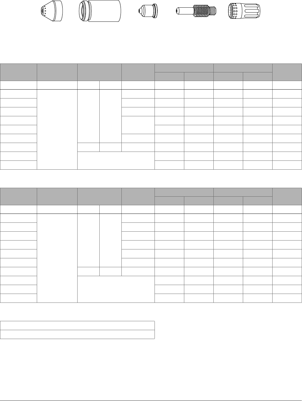
Cut Charts and Marking Charts
9
Powermax45 XP Operator Manual 809240 133
Stainless Steel – 45 A – Air – Shielded
Metric
Material
Thickness
Torch-to-Work
Distance
Initial Pierce Height
Pierce
Delay Time
Best Quality Settings Production Settings
Kerf Width
Cut Speed Voltage Cut Speed Voltage
mm mm mm % seconds mm/min volts mm/min volts mm
2
1.5
3.8 250
0.1 5620 126 7830 129 0.6
3 0.2 3285 129 4725 128 0.9
4 0.4 1995 130 2960 129 1.1
6
0.6
1145 131 1695 131 1.2
8 830 1341100134 1.4
10 0.8 605 137 870 137 1.6
12 4.6 300 1.2 380 141 540 139 1.8
16
Edge Start
240 145 320 142 2.4
20 160 149 205 146 3.1
English
Material
Thickness
Torch-to-Work
Distance
Initial Pierce Height
Pierce
Delay Time
Best Quality Settings Production Settings
Kerf Width
Cut Speed Voltage Cut Speed Voltage
inches inches inches % seconds in/min volts in/min volts inches
16 GA
0.06
0.15 250
0.1 237 125 320 128 0.017
14 GA 0.2 230 126 320 129 0.022
10 GA 0.4 90 130 134 128 0.041
3/16 0.5 63 131 93 130 0.044
1/4 0.6 40 131 59 131 0.047
3/8 0.8 26 137 29 136 0.061
1/2 0.18 300 1.2 12 142 19 140 0.075
5/8
Edge Start
10 145 13 142 0.096
3/4 7 148 9 145 0.116
7/8 5 151 6 149 0.137
Gas flow rate – slpm / scfh
151 / 320 Hot (cutflow)
184 / 390 Cold (postflow)
220817 220854
(220953 for
ohmic sensing)
220941 220857220842

Cut Charts and Marking Charts
9
134 809240 Operator Manual Powermax45 XP
Aluminum – 45 A – Air – Shielded
Metric
Material
Thickness
Torch-to-Work
Distance
Initial Pierce Height
Pierce
Delay Time
Best Quality Settings Production Settings
Kerf Width
Cut Speed Voltage Cut Speed Voltage
mm mm mm % seconds mm/min volts mm/min volts mm
2
1.5
3.8 250
0.1 7890 121 9585 134 1.3
3 0.2 4850 130 7120 129
1.5
4 0.4 3670 133 5650 129
6 0.5 2060 139 3095 132 1.6
8 0.6 1330 139 1830 136 1.7
10 0.7 860 142 1015 140 1.9
12
Edge Start
620 144 745 142 2
16 360 152 340 148 2.5
English
Material
Thickness
Torch-to-Work
Distance
Initial Pierce Height
Pierce
Delay Time
Best Quality Settings Production Settings
Kerf Width
Cut Speed Voltage Cut Speed Voltage
inches inches inches % seconds in/min volts in/min volts inches
1/10
0.06
0.15 250
0.2 240 126 320 131 0.056
1/8
0.4
170 131 263 128 0.060
3/16 120 134 184 130 0.061
1/4 0.5 70 137 104 132 0.063
3/8 0.7 36 141 42 139 0.073
1/2
Edge Start
21 145 26 143 0.082
5/8 15 152 14 148 0.100
3/4 8 158 9 153 0.117
Gas flow rate – slpm / scfh
151 / 320 Hot (cutflow)
184 / 390 Cold (postflow)
220817 220854
(220953 for
ohmic sensing)
220941 220857220842
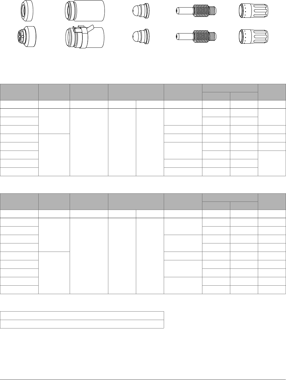
Cut Charts and Marking Charts
9
Powermax45 XP Operator Manual 809240 135
Mild Steel – FineCut – Air – Shielded and Unshielded
Metric
Material Thickness Current
Torch-to-Work
Distance
Initial Pierce Height Pierce Delay Time
Recommended
Kerf Width
Cut Speed Voltage
mm A mm mm % seconds mm/min volts mm
0.5
40
1.5 3.8 250
0.0
8250 78
0.7
0.6 8250 78
0.8 0.1 8250 78 0.6
1
45
0.2 8250 78 0.7
1.5
0.4
6400 78 1.2
2 4800 78
1.33 0.5 2500 78
4 0.6 1900 78
English
Material Thickness Current
Torch-to-Work
Distance
Initial Pierce Height Pierce Delay Time
Best Quality Settings
Kerf Width
Cut Speed Voltage
inches A inches inches % seconds in/min volts inches
26 GA
40
0.06 0.15 250
0.0
325 78 0.025
24 GA 325 78 0.029
22 GA
0.1
325 78 0.024
20 GA 325 78 0.020
18 GA
45
0.2 325 78 0.043
16 GA
0.4
250 78 0.046
14 GA 200 78 0.049
12 GA
0.5
120 78 0.052
10 GA 95 78 0.051
Gas flow rate – slpm / scfh
155 / 330 Hot (cutflow)
215 / 460 Cold (postflow)
220955 (deflector)
220948 (shield)
220854
220953 (ohmic)
220930 220947220842
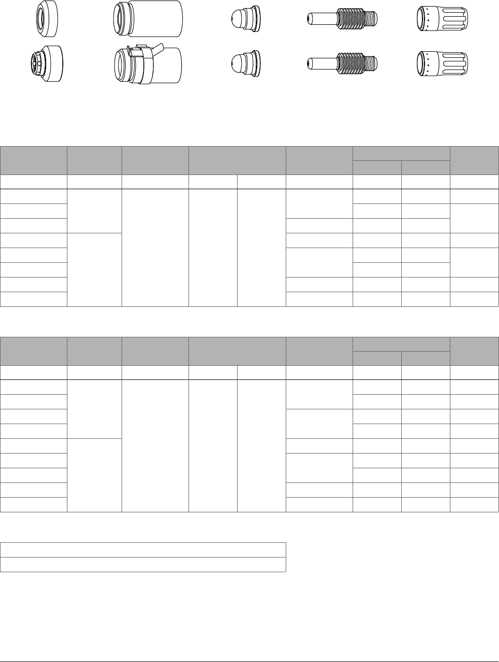
Cut Charts and Marking Charts
9
136 809240 Operator Manual Powermax45 XP
Stainless Steel – FineCut – Air – Shielded and Unshielded
Metric
Material Thickness Current
Torch-to-Work
Distance
Initial Pierce Height Pierce Delay Time
Recommended
Kerf Width
Cut Speed Voltage
mm A mm mm % seconds mm/min volts mm
0.5
40
0.5 2.0 400
0.0
8250 68 0.6
0.6 8250 68
0.5
0.8 0.1 8250 68
1
45
0.2 8250 68 0.6
1.5
0.4
6150 70
1.0
2 4800 71
3 0.5 2550 80 1.4
40.61050841.5
English
Material Thickness Current
Torch-to-Work
Distance
Initial Pierce Height Pierce Delay Time
Best Quality Settings
Kerf Width
Cut Speed Voltage
inches A inches inches % seconds in/min volts inches
26 GA
40
0.02 0.08 400
0.0
325 68 0.024
24 GA 325 68 0.021
22 GA
0.1
325 68 0.018
20 GA 325 68 0.017
18 GA
45
0.2 325 68 0.036
16 GA
0.4
240 70 0.039
14 GA 200 70 0.040
12 GA 0.5 120 80 0.049
10 GA 0.6 75 80 0.055
Gas flow rate – slpm / scfh
155 / 330 Hot (cutflow)
215 / 460 Cold (postflow)
220955 (deflector)
220948 (shield)
220854
220953 (ohmic)
220930 220947220842

Cut Charts and Marking Charts
9
Powermax45 XP Operator Manual 809240 137
Mild Steel – FineCut Low Speed – Air – Shielded and Unshielded
Metric
Material Thickness Current
Torch-to-Work
Distance
Initial Pierce Height Pierce Delay Time
Recommended
Kerf Width
Cut Speed Voltage
mm A mm mm % seconds mm/min volts mm
0.5
30
1.5 3.8 250
0.0
3800 69
0.60.6 3800 68
0.8 0.1 3800 70
1*
40
0.2 3800 72
0.8
1.5*
0.4
3800 75
2
45
3700 76 0.7
30.52750781.3
4 0.6 1900 78 1.5
English
Material Thickness Current
Torch-to-Work
Distance
Initial Pierce Height Pierce Delay Time
Best Quality Settings
Kerf Width
Cut Speed Voltage
inches A inches inches % seconds in/min volts inches
26 GA
30
0.06 0.15 250
0.0
150 70 0.026
24 GA 150 68 0.024
22 GA
0.1
150 70
0.025
20 GA 150 71
18 GA
40
0.2 150 73 0.031
16 GA*
0.4
150 75 0.029
14 GA*
45
150 76 0.027
12 GA
0.5
120 78 0.052
10 GA 95 78 0.051
Gas flow rate – slpm / scfh
155 / 330 Hot (cutflow)
215 / 460 Cold (postflow)
* Not a dross-free cut.
220955 (deflector)
220948 (shield)
220854
220953 (ohmic)
220930 220947220842
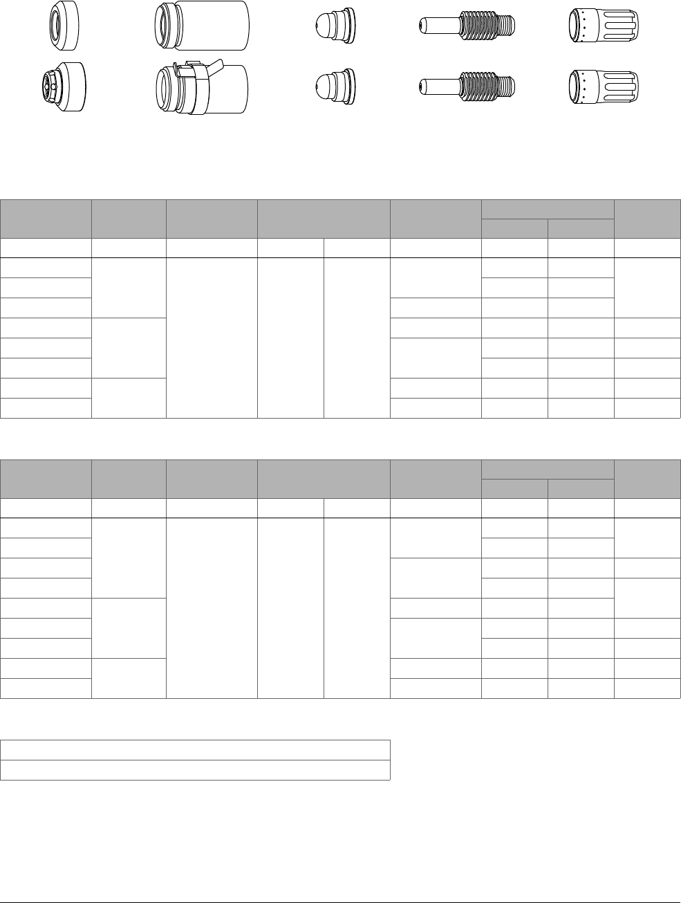
Cut Charts and Marking Charts
9
138 809240 Operator Manual Powermax45 XP
Stainless Steel – FineCut Low Speed – Air – Shielded and Unshielded
Metric
Material Thickness Current
Torch-to-Work
Distance
Initial Pierce Height Pierce Delay Time
Recommended
Kerf Width
Cut Speed Voltage
mm A mm mm % seconds mm/min volts mm
0.5
30
0.5 2.0 400
0.0
3800 69
0.70.6 3800 69
0.8 0.1 3800 69
1
40
0.2 3800 69 0.6
1.5
0.4
2900 69 0.5
2 2750 69 1.3
3
45
0.5 2550 80 1.4
40.61050801.5
English
Material Thickness Current
Torch-to-Work
Distance
Initial Pierce Height Pierce Delay Time
Best Quality Settings
Kerf Width
Cut Speed Voltage
inches A inches inches % seconds in/min volts inches
26 GA
30
0.02 0.08 400
0.0
150 69
0.028
24 GA 150 69
22 GA
0.1
150 69 0.025
20 GA 150 69
0.023
18 GA
40
0.2 145 69
16 GA
0.4
115 69 0.022
14 GA 110 69 0.021
12 GA
45
0.5 120 80 0.049
10 GA 0.6 75 80 0.055
Gas flow rate – slpm / scfh
155 / 330 Hot (cutflow)
215 / 460 Cold (postflow)
220955 (deflector)
220948 (shield)
220854
220953 (ohmic)
220930 220947220842
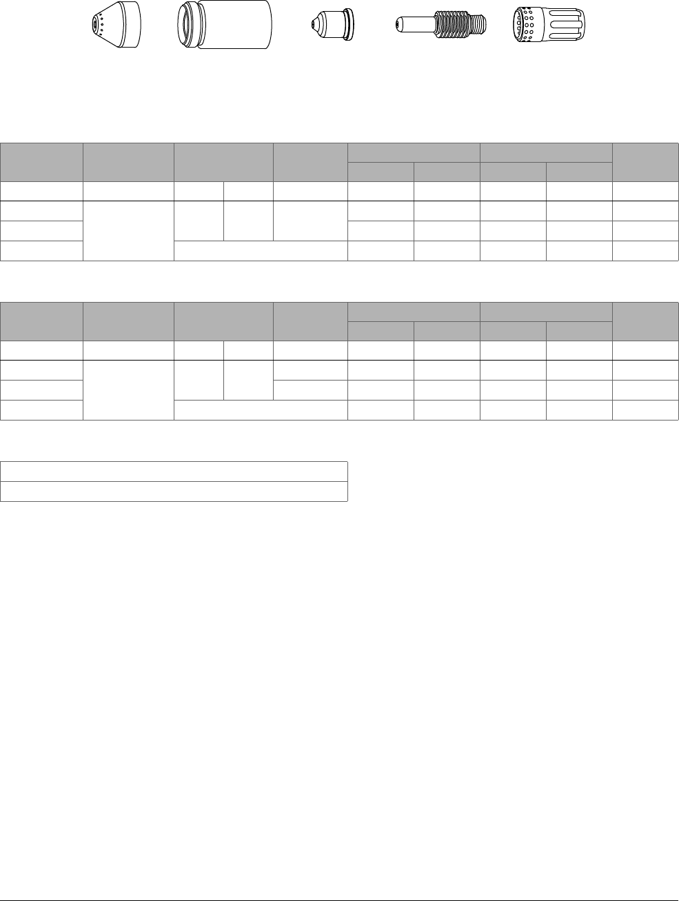
Cut Charts and Marking Charts
9
Powermax45 XP Operator Manual 809240 139
Stainless Steel – 45 A – F5 – Shielded
F5 is not recommended for thicknesses less than 7 mm or 1/4 inch or for use
with FineCut consumables.
Metric
Material
Thickness
Torch-to-Work
Distance
Initial Pierce Height
Pierce
Delay Time
Best Quality Settings Production Settings
Kerf Width
Cut Speed Voltage Cut Speed Voltage
mm mm mm % seconds mm/min volts mm/min volts mm
8
1.5
3.8 250 0.8
630 150 860 144 2.1
10 435 153 525 147 2.3
12 Edge Start 340 156 440 150 2.5
English
Material
Thickness
Torch-to-Work
Distance
Initial Pierce Height
Pierce
Delay Time
Best Quality Settings Production Settings
Kerf Width
Cut Speed Voltage Cut Speed Voltage
inches inches inches % seconds in/min volts in/min volts inches
1/4
0.06
0.15 250
0.6 32 147 47 141 0.075
3/8 0.8 18 152 22 146 0.088
1/2 Edge Start 12 157 16 151 0.101
Gas flow rate – slpm / scfh
149 / 315 Hot (cutflow)
184 / 390 Cold (postflow)
220817 220854
(220953 for
ohmic sensing)
220941 220857220842

Cut Charts and Marking Charts
9
140 809240 Operator Manual Powermax45 XP
Marking and Dimpling – Air – Shielded
Mild steel
Current Torch-to-Work Distance Initial Marking Height Delay Time Marking Speed Arc Voltage Width Depth
A mm in mm in seconds mm/min in/min volts mm in mm in
Light marking
10 6.4 0.25 6.4 0.25 0 2540 100 134 2.79 0.11 <0.02 <0.001
Heavy marking
10 4.6 0.18 4.6 0.18 0 2540 100 111 2.79 0.11 0.09 0.0035
Dimpling
10 6.4 0.25 — — 0.05 — — — 1.98 0.078 0.25 0.01
Stainless steel
Current Torch-to-Work Distance Initial Marking Height Delay Time Marking Speed Arc Voltage Width Depth
A mm in mm in seconds mm/min in/min volts mm in mm in
Light marking
10 5.1 0.2 5.1 0.2 0 5080 200 123 2.03 0.08 <0.02 <0.001
Heavy marking
10 6.4 0.25 6.4 0.25 0 3175 125 133 2.54 0.1 0.08 0.003
Dimpling
10 6.4 0.25 — — 0.05 — — — 2.03 0.08 0.23 0.009
Aluminum
Current Torch-to-Work Distance Initial Marking Height Delay Time Marking Speed Arc Voltage Width Depth
A mm in mm in seconds mm/min in/min volts mm in mm in
Marking
11 2.5 0.1 5.1 0.2 0 5080 200 98 0.89 0.035 <0.02 <0.001
Dimpling
10 3.2 0.125 — — 0.15 — — — 0.89 0.035 0.09 0.0035
Gas flow rate – slpm / scfh
136 / 290 Hot (cutflow)
141 / 300 Cold (postflow)
420542 220854
(220953 for
ohmic sensing)
420415 220857220842
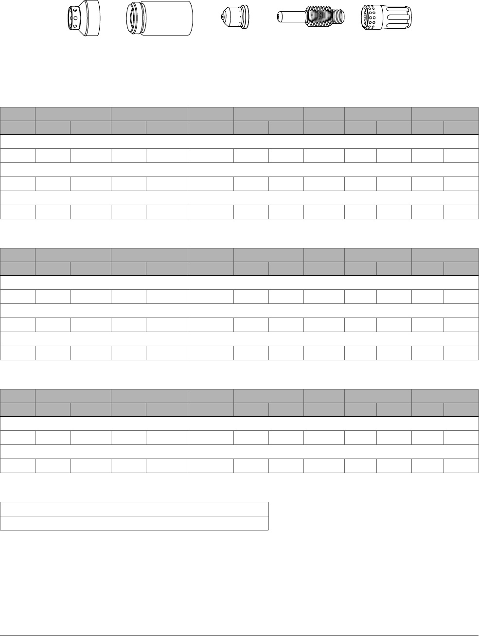
Cut Charts and Marking Charts
9
Powermax45 XP Operator Manual 809240 141
Marking and Dimpling – Argon – Shielded
Mild steel
Current Torch-to-Work Distance Initial Marking Height Delay Time Marking Speed Arc Voltage Width Depth
A mm in mm in seconds mm/min in/min volts mm in mm in
Light marking
10 2.0 0.08 2.0 0.08 0 3175 125 44 1.22 0.048 <0.02 <0.001
Heavy marking
15 1.5 0.06 1.5 0.06 0 3175 125 42 1.22 0.048 <0.02 <0.001
Dimpling
20 3.2 0.125 — — 0.25 — — — 0.99 0.039 <0.02 <0.001
Stainless steel
Current Torch-to-Work Distance Initial Marking Height Delay Time Marking Speed Arc Voltage Width Depth
A mm in mm in seconds mm/min in/min volts mm in mm in
Light marking
12 2.5 0.1 2.5 0.1 0 3175 125 46 1.40 0.055 <0.02 <0.001
Heavy marking
15 2.5 0.1 2.5 0.1 0 2540 100 46 2.16 0.085 0.02 0.001
Dimpling
10 3.2 0.125 — — 0.25 — — — 0.94 0.037 0.18 0.007
Aluminum
Current Torch-to-Work Distance Initial Marking Height Delay Time Marking Speed Arc Voltage Width Depth
A mm in mm in seconds mm/min in/min volts mm in mm in
Marking
16 0.5 0.02 0.5 0.02 0 4445 175 42 0.63 0.025 <0.02 <0.001
Dimpling
20 0.5 0.02 — — 0.4 — — — 0.66 0.026 0.04 0.0015
Gas flow rate – slpm / scfh
120 / 255 Hot (cutflow)
122 / 260 Cold (postflow)
420542 220854
(220953 for
ohmic sensing)
420415 220857220842

Cut Charts and Marking Charts
9
142 809240 Operator Manual Powermax45 XP

Powermax45 XP Operator Manual 809240 143
Troubleshooting Guide
The following sections provide an overview of the most common problems that may arise when
using this system and suggest ways to solve them.
If you are unable to fix the problem by following this basic troubleshooting guide or if you need
further assistance:
1. Call your Hypertherm distributor or authorized Hypertherm repair facility.
2. Call the nearest Hypertherm office listed in the front of this manual.
WARNING
INSTANT-ON TORCHES – PLASMA ARC CAN CAUSE INJURY, BURNS
The plasma arc ignites immediately when you pull the torch trigger.
Before changing consumables, one of the following actions must be
taken. Whenever possible, complete the first action.
Turn OFF (O) the plasma power supply.
OR
Move the torch-disable switch to the yellow lock (X) position
(closest to the torch lead). Pull the trigger to make sure the
torch does not fire a plasma arc.

Troubleshooting Guide
10
144 809240 Operator Manual Powermax45 XP
Common cutting issues
Problem Solution
The cut quality is poor. • Make sure the correct consumables are installed. See page 63 for hand
cutting consumables. See page 111 for mechanized cutting
consumables. See page 75 for gouging consumables. See page 119 for
marking consumables.
• Loosen the consumables about 1/8
th
of a turn and try again. Never tighten
the consumables more than finger-tight. See page 48. It is normal for
some gas to escape between the torch shell and the retaining cap during
use. This is part of the torch design.
• Inspect and replace the consumable parts if they are worn or damaged,
including the swirl ring. See page 165. Always replace the nozzle and
electrode together.
• Make sure that the correct mode is selected: cut mode for cutting and
piercing applications or gouge/marking mode for gouging and marking
applications. See page 53.
• Make sure that the work lead connection to the plasma power supply is
secure. Make sure that there is no damage to the work lead.
• Make sure that the torch is being used correctly. See Cut with the Hand
Torch on page 61 or Cut with the Machine Torch on page 111.
• Check the gas pressure and the gas supply hose. See page 148.
• Inspect the gas filtration system for signs of contaminants that may be
interfering with system performance. See page 149.
• Adjust the cut speed.
• Operate the system without using an extension cord. If you must use an
extension cord, use a heavy conductor cord of the shortest possible
length. Seepage36.
The arc sputters and
hisses.
• Inspect the gas filtration system for signs of moisture. See page 149.

Troubleshooting Guide
10
Powermax45 XP Operator Manual 809240 145
Hand cutting issues
Problem Solution
Pulling the torch trigger
does not fire an arc.
Instead, the torch blows
out short puffs of air and
the power supply sounds
like it is releasing
pressure.
• The first time you pull the torch trigger after you set the torch-disable
switch to the “ready to fire” ( ) position, the torch may emit multiple
puffs of air in quick succession. With each puff of air, the torch vibrates
slightly, and plasma power supply emits a pressure-release sound. This is
a warning that occurs when you lock and then unlock the torch without
turning OFF the power supply. (The Torch Cap LED also illuminates –
seepage156.) This does not indicate a fault condition. The purpose of
the warning is to alert you that the torch is activated and will fire a plasma
arc the next time you pull the trigger. See page 47.
The plasma arc sputters,
and consumable life is
shorter than expected.
• Make sure that the consumables are installed correctly. See page 48.
• Inspect and replace the consumable parts if they are worn or damaged.
See page 165. Always replace the nozzle and electrode together.
• Check the gas pressure and the gas supply hose. See page 148.
• Inspect the gas filtration system for signs of moisture. See page 149.
The torch does not fire an
arc after repeated
attempts. No issues with
incoming power or gas
supply are apparent. No
fault LEDs or fault codes
display.
• Test the torch-disable switch to see if it is working properly.
See page 163. Replace the switch if it is broken or not working correctly.
The plasma arc does not
transfer to the workpiece.
• Clean the area where the work clamp contacts the workpiece. Remove
any rust, paint, or other residue. Make sure there is good metal-to-metal
contact.
• Inspect the work clamp for damage. Repair or replace it if necessary.
• Move the torch closer to the workpiece and fire the torch again. See Cut
with the Hand Torch on page 61.
The plasma arc blows out
but re-ignites when the
torch trigger is pulled
again.
• Decrease the length of the arc stretch. Whenever possible, drag the torch
on the workpiece. See page 72.
• If you are using the Maximum Control gouging consumables, make sure
the system is set to gouge/marking mode and the output current is set to
26 – 45 A. Setting the output current below 26 A with these
consumables can cause the arc to extinguish.
• Inspect and replace the consumable parts if they are worn or damaged.
See page 165. Always replace the nozzle and electrode together.
• Make sure the incoming gas supply hose has an internal diameter of
9.5 mm (3/8 inch) or greater.
• Inspect the gas filtration system for signs of contaminants that may be
interfering with system performance. See page 149.
• If you manually adjusted the gas pressure before this issue occurred, reset
the gas pressure to the default setting. See page 58.

Troubleshooting Guide
10
146 809240 Operator Manual Powermax45 XP
Mechanized cutting issues
The torch does not cut
completely through the
workpiece.
• Make sure the system is set to cut mode, not gouge/marking mode.
Seepage53.
• Decrease your cut speed.
• Inspect and replace the consumable parts if they are worn or damaged.
See page 165. Always replace the nozzle and electrode together.
• Make sure that the torch is being used correctly. See Cut with the Hand
Torch on page 61.
• Make sure the consumables installed on the torch match the selected
mode. For example, do not use gouging consumables when the system is
set to cut mode. See page 53.
• Increase the output current (amperage) on the plasma power supply.
Seepage53.
• If the output current cannot be increased, determine if the metal being cut
exceeds the maximum capacity for this system. See Cutting specifications
on page 24.
• Clean the area where the work clamp contacts the workpiece. Remove
any rust, paint, or other residue. Make sure there is good metal-to-metal
contact.
• Inspect the torch lead. Straighten it out if it is twisted or kinked. Replace it
if it is damaged.
• Check the gas pressure and the gas supply hose. See page 148.
• Adjust the gas flow rate. See Gas supply source on page 38.
Problem Solution
The machine torch does
not fire an arc. Instead,
the torch blows out short
puffs of air and the power
supply sounds like it is
releasing pressure.
• The first time you send a start signal to the torch after you set the
torch-disable switch to the “ready to fire” ( ) position, the torch may
emit multiple puffs of air in quick succession. With each puff of air, the
torch vibrates slightly, and plasma power supply emits a pressure-release
sound. This is a warning that occurs when you lock and then unlock the
torch without turning OFF the power supply. (The Torch Cap LED also
illuminates – see page 156.) This does not indicate a fault condition.
The purpose of the warning is to alert you that the torch is activated and
will fire a plasma arc the next time it receives a start signal. See page 47.
The torch’s pilot arc
initiates but does not
transfer to the workpiece.
• Clean the metal surface of any rust, paint, or other residue that may
prevent a good metal-to-metal connection.
• Make sure that the work lead is making good contact with the cutting
table.
• Make sure that the cutting table is properly grounded and is making good
contact with the workpiece.
• Decrease the torch-to-work distance (cut height). Refer to the cut charts
starting on page 129.
Problem Solution

Troubleshooting Guide
10
Powermax45 XP Operator Manual 809240 147
The cut angle is not
square.
• Make sure that the torch is square to the workpiece.
• Check the gas pressure and the gas supply hose. See page 148.
• Inspect and replace the consumable parts if they are worn or damaged.
See page 165. Always replace the nozzle and electrode together.
• Make sure the direction of the torch travel is correct. The best quality cut
is always on the right with respect to the forward motion of the torch.
• Make sure the cut chart parameters or the program code values are
correct. Adjust the torch-to-work distance (cut height) and the cut speed
as needed. Refer to the cut charts starting on page 129.
The torch does not
completely pierce the
workpiece, and there is
excessive sparking on
the top of the workpiece.
• Clean the metal surface of any rust, paint, or other residue that may
prevent a good metal-to-metal connection.
• Make sure that the work lead is making good contact with the cutting
table. Make sure that the cutting table is properly grounded and is making
good contact with the workpiece.
• Inspect and replace the consumable parts if they are worn or damaged.
See page 165. Always replace the nozzle and electrode together.
• Make sure the cut chart parameters or the program code values are
correct. Try decreasing the cut speed. Refer to the cut charts starting on
page 129.
• Increase the output current (amperage) on the plasma power supply.
Seepage53.
• If the output current cannot be increased, determine if the metal being cut
exceeds the maximum capacity for this system. See Cutting specifications
on page 24.
• Inspect the torch lead. Straighten it out if it is twisted or kinked. Replace it
if it is damaged.
• Make sure the incoming gas supply hose has an internal diameter of
9.5 mm (3/8 inch) or greater.
Excessive dross forms on
the bottom of the cut.
• Check the gas pressure and the gas supply hose. See page 148.
• Inspect and replace the consumable parts if they are worn or damaged.
See page 165. Always replace the nozzle and electrode together.
• Make sure the cut chart parameters or the program code values are
correct. Try adjusting the cut speed. Refer to the cut charts starting on
page 129.
• Increase the output current (amperage) on the plasma power supply.
Seepage53.
• Inspect the torch lead. Straighten it if it is twisted or kinked. Replace it if it
is damaged.
Problem Solution

Troubleshooting Guide
10
148 809240 Operator Manual Powermax45 XP
Check the gas pressure
Gas supply: Incorrect gas pressure can result in issues with cut quality and cut
performance. Refer to Gas supply source on page 38 for details on the inlet gas supply
requirements for this system. Never exceed the maximum gas pressure of 9.3 bar
(135 psi).
Gas hose: An incoming gas supply hose with too small a diameter can result in issues with
cut quality and cut performance. Only use gas hoses with an internal diameter of 9.5 mm
(3/8 inch) or greater.
Pressure setting: The system regulates gas pressure automatically, but you can adjust the
gas pressure manually if needed. See page 56.
Gas test: You can run a gas test to see if adequate pressure is exiting the torch. The gas
test lets you see the actual gas pressure of the plasma system so that you can compare it to
the inlet set pressure. See page 157.
If you manually adjusted the gas pressure and then started to notice
issues with cut quality or cut performance, reset the gas pressure to the
default setting. Seepage58.
The consumables wear
out more quickly than
they used to.
• Check the gas pressure and the gas supply hose. See page 148.
• Do not start or end cuts off of the surface of the workpiece. Starting at the
edge of the workpiece is acceptable as long as the arc makes contact
with the workpiece when started.
• Inspect the torch lead. Straighten it if it is twisted or kinked. Replace it if it
is damaged.
• Make sure the arc current, arc voltage, travel speed, and other cut settings
are correct. Refer to the cut charts starting on page 129.
• Use the correct torch height for piercing. Refer to the cut charts starting
on page 129 for the initial pierce height.
• Make sure that the pierce delay time is correct. Refer to the cut charts
starting on page 129.
• Inspect the shield, swirl ring, and retaining cap. Replace them if they are
worn or damaged. See page 165.
• Inspect the gas filtration system for signs of contaminants that may be
interfering with system performance. See page 149.
• A faulty pilot arc IGBT may be shortening nozzle life. Contact your
distributor or authorized repair facility.
Problem Solution

Troubleshooting Guide
10
Powermax45 XP Operator Manual 809240 149
Check the gas quality
It is extremely important to maintain a clean, dry gas line in order to:
Prevent oil, water, dirt, and other contaminants from damaging internal components.
Achieve optimal cut quality and consumable life.
Dirty, oily air is the root cause of many common problems that occur in Powermax systems, and in
some instances it can void the warranty on the power supply and on the torch. See the gas quality
recommendations in the ratings table on page 23.
The built-in air filter in the system is designed to filter out particulates as small as 5 microns. It can
remove some moisture from the gas supply. However, if you work in an environment that is extremely
warm and humid, or if work site conditions introduce oil, vapor, or other contaminants into the gas
line, install an external filtration system that cleans the gas supply before it enters the plasma power
supply. See page 42.
To maintain a clean gas line:
1. Examine the air filter element in the system’s built-in air filter. Replace
it if it is contaminated. See page 167.
2. Clean the air filter bowl that houses the air filter element. Make sure it
is free from oil, dirt, and other contaminants.
A yellow residue on the filter bowl often indicates that oil is
getting into the gas supply line.
3. Examine the O-ring at the top of the air filter bowl. Replace it if it is cracked or damaged.
Seepage165.
4. If you are using an external air filtration system, clean or replace any parts in it that may be
contaminated.
NOTICE
Synthetic lubricants containing esters that are used in some air compressors will damage
polycarbonates used in the air filter bowl.

Troubleshooting Guide
10
150 809240 Operator Manual Powermax45 XP
Cold restarts and quick restarts
To restart the system, turn OFF (O) the power
switch on the plasma power supply and then
turn ON (I) the power switch again.
In some instances, you may be asked
specifically to perform a “cold restart” or a
“quick restart.”
Perform a cold restart
1. Set the power switch on the plasma power supply to the OFF (O) position.
2. Wait a minimum of 30 seconds.
3. Set the power switch on the plasma power supply to the ON (I) position.
Perform a quick restart
1. Set the power switch on the plasma power supply to the OFF (O) position.
2. Immediately set the power switch on the plasma power supply back to the ON (I) position.
If a fault occurs while using a generator, a quick restart may not clear the
fault. Instead, turn OFF (O) the plasma power supply and wait
60 – 70 seconds before turning it ON (I) again.

Troubleshooting Guide
10
Powermax45 XP Operator Manual 809240 151
Fault LEDs and fault codes
Some fault conditions cause one or more fault LEDs to illuminate or blink.
Other fault conditions display a fault code in addition to the fault LEDs. The fault code
provides additional information when needed to make the source of the problem easier to
identify.
Fault codes follow the format N-nn-n. They blink on the 2-digit display in increments:
If the Cut Mode LED or the Gouge/Marking Mode
LED blinks, this indicates that the gas pressure has
been manually adjusted. See page 56. It does not
indicate a fault condition. When you reset the gas
pressure to its default setting, the LED stops
blinking. See page 58.
Refer to the following table to identify and troubleshoot each fault condition. A label with
descriptions for several common fault codes can be found inside the front cover of the Operator
Manual. Peel off the label and place it on the power supply or near your work area for reference.
The 0-12-n output gas pressure faults are not listed in this table. These
fault codes do not stop the system from operating and do not appear on
the 2-digit display. They display only on a CNC via an RS-485 serial
interface.
Temperature fault LED (yellow)
Torch Cap fault LED (yellow)
System Fault LED (yellow)
Gas Pressure fault LED (yellow)
Power ON LED (green)
N- -nnn
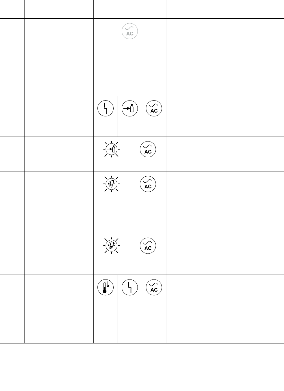
Troubleshooting Guide
10
152 809240 Operator Manual Powermax45 XP
Fault
code
Description LED behavior Solutions
None The ON/OFF power
switch is set to ON (I), but
the Power ON LED does
not illuminate.
OFF
• Make sure that the power cord is plugged
into the receptacle.
• Make sure that the power is on at the main
power panel or at the disconnect-power
switch box.
• Make sure that the line voltage is not too
low (more than 10% below the rated
voltage for 1-phase models or 15% below
the rated voltage for 3-phase models).
See page 23 and page 31.
None Low gas pressure
ON ON ON
• The gas pressure is below the minimum
pressure for that process, mode, torch,
and lead length.
• Check the input gas supply. See Gas
Pressure fault LED on page 155.
None No gas input
Blinks ON
• Connect the input gas supply to the
plasma power supply. Turn OFF (O) then
turn ON (I) the power supply. See Gas
Pressure fault LED on page 155.
None Torch stuck open (TSO)
The nozzle and electrode
are not touching after a
start signal is received.
Blinks slowly ON
• Turn OFF (O) the power supply. Make
sure that the consumables are installed
correctly and that they are in good
condition. See Torch Cap fault LED on
page 156.
• If you are using FlushCut consumables,
make sure the retaining ring is fully
tightened onto the cap.
None Torch stuck closed (TSC)
The nozzle and electrode
will not separate after a
start signal is received.
Blinks
rapidly
ON
• Turn OFF (O) the power supply. Make
sure that the consumables are installed
correctly and that they are in good
condition. See Torch Cap fault LED on
page 156.
None Power supply is over
temperature or under
temperature
ON ON ON
• The system may have overheated. Leave
the plasma power supply ON to allow the
fan to cool the internal components. See
Understand duty cycle to prevent
overheating on page 60.
• The system may be too cold to operate. If
the internal temperature of the plasma
power supply approaches -30°C (-22°F),
move the system to a warmer location.
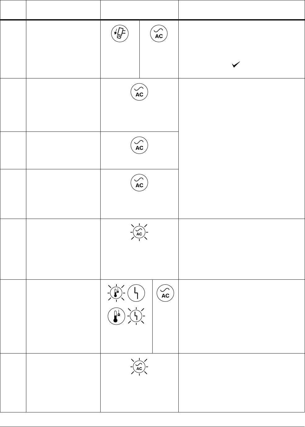
Troubleshooting Guide
10
Powermax45 XP Operator Manual 809240 153
None Retaining cap off
ON ON
• Turn OFF (O) the power supply. Make
sure that the torch is connected to the
power supply and the consumables are
installed correctly. Make sure the
torch-disable switch is set to the green
“ready to fire” ( ) position. See Torch
Cap fault LED on page 156.
0-11-0 Remote controller mode
invalid. Valid remote
modes for this system:
• 1, 2 – Continuous
pilot arc
•3–Gouge
ON
There is a problem with the remote controller
or the software interface to the system. The
system cannot interpret the mode, output
current, or gas pressure information coming
from the controller.
• Fix the controller.
• Check the RS-485 interface cable.
• Examine the programming code for
incorrect process variables.
0-11-1 Remote controller current
invalid. Valid remote
current settings for this
system: 10 – 45 A.
ON
0-11-2 Remote controller
pressure invalid. Valid
remote pressure settings
for this system depend on
the process, mode, torch,
and torch lead.
ON
0-13-0 Alternating current (AC)
input power unstable
(system continues to
operate)
Blinks
• Perform a cold restart.
• If applicable, disconnect the system from
generator power. See Generator
considerations on page 157.
• If the fault does not clear, have an
electrical technician correct the power
source. Seepage30.
0-51-0 Start/trigger signal on at
power up
This condition indicates
that the power supply is
receiving a start signal. It
is sometimes referred to
as a “stuck start.”
Blinks alternately
ON
• Hand torch: The torch trigger was being
held in the “fire” position while the plasma
power supply was being powered ON (I).
Release the trigger and restart the power
supply.
• Machine torch: The plasma power supply
was receiving a start signal when it was
powered ON (I). Turn off the start signal
and restart the power supply.
0-60-0 Alternating current (AC)
input voltage phase loss
Blinks
• Have an electrical technician check all
input phases and fuses/breakers for
proper voltage at the power source and at
the plasma system.
• If applicable, disconnect the system from
generator power. See Generator
considerations on page 157.
Fault
code
Description LED behavior Solutions
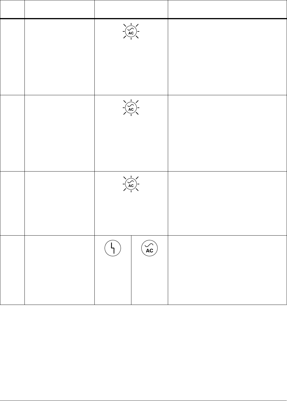
Troubleshooting Guide
10
154 809240 Operator Manual Powermax45 XP
0-60-1 Alternating current (AC)
input voltage too low
Blinks
• The input line voltage is too low (more
than 10% below the rated voltage for
1-phase models or 15% below the rated
voltage for 3-phase models). Have an
electrical technician check the line and
increase the voltage. See page 23 and
page 31.
• If applicable, disconnect the system from
generator power. See Generator
considerations on page 157.
0-60-2 Alternating current (AC)
input voltage too high
Blinks
• The input line voltage is too high (more
than 10% above the rated voltage for
1-phase models or 20% above the rated
voltage for 3-phase models). Have an
electrical technician check the line and
decrease the voltage. See page 23 and
page 31.
• If applicable, disconnect the system from
generator power. See Generator
considerations on page 157.
0-61-0 Alternating current (AC)
input unstable – system
shutdown
Blinks
• The current from the incoming power line
is unstable. Power down and correct the
line resonance problem before continuing.
• Make sure the plasma system is not being
used on a phase converter.
• If applicable, disconnect the system from
generator power. See Generator
considerations on page 157.
1-nn-n
2-nn-n
3-nn-n
Major fault
ON ON
• An internal component may be faulty.
Restart the plasma power supply. In some
instances, a restart can clear the fault
condition.
• If restarting the plasma power supply
does not clear the fault, a qualified service
technician must service the system.
Contact your distributor or authorized
repair facility.
Fault
code
Description LED behavior Solutions
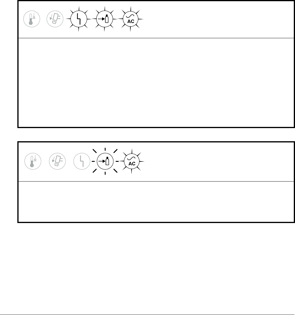
Troubleshooting Guide
10
Powermax45 XP Operator Manual 809240 155
Gas Pressure fault LED
The minimum gas pressure required varies based on:
Selected mode (cut or gouge)
Type of torch
Length of torch lead
For example, if you select cut mode and are using a hand torch with a 6 m (20 foot) lead, the
Gas Pressure LED and System Fault LED illuminate if the inlet gas pressure is less than 3.8 bar
(55 psi).
The Gas Pressure LED and System Fault LED
illuminate while the system is powered ON.
The input gas pressure is too low.
• Check all the connections for the input gas supply. Make sure there are no leaks or loose connections.
• Make sure the incoming gas supply hose has an internal diameter of 9.5 mm (3/8 inch) or greater.
• Check the inlet gas pressure. Adjust as needed. See page 37.
• Manually adjust the gas pressure on the plasma system. See page 56. Perform a quick restart.
• Run a gas test. See page 157. Compare the inlet set pressure against the actual output gas pressure.
If there is no apparent issue with the inlet gas supply, check the air filter bowl and air filter element in
the plasma power supply. Clean or replace as needed. See page 167.
• If the problem persists, have an authorized service technician examine the system. Contact your
distributor or authorized repair facility.
The Gas Pressure LED blinks while the system is
powered ON.
The input gas supply is not connected to the plasma power supply.
• Make sure the input gas supply is properly connected to the plasma system.
• Check all the connections for the input gas supply. Make sure there are no leaks or loose connections.
• Restart the plasma power supply.
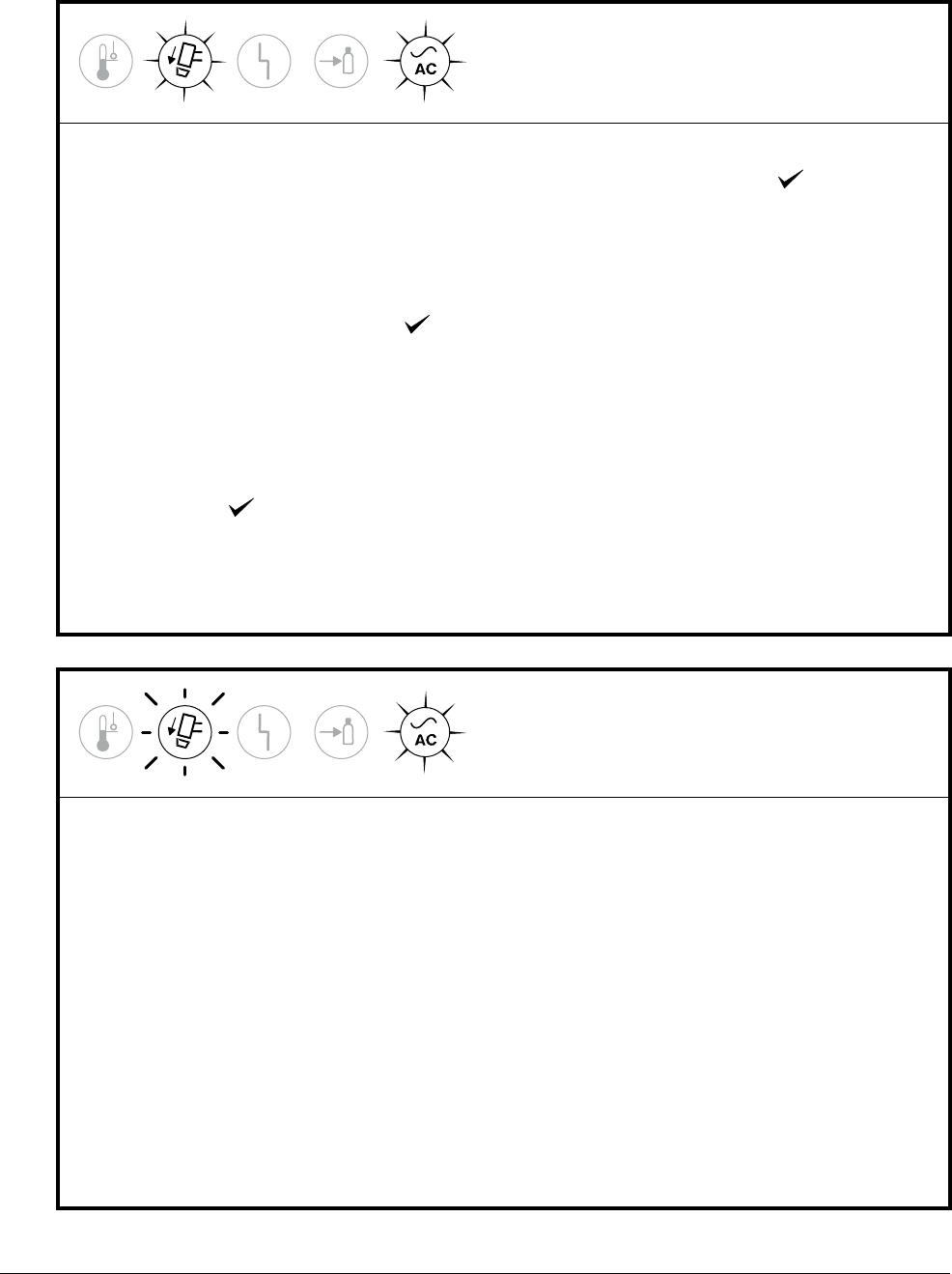
Troubleshooting Guide
10
156 809240 Operator Manual Powermax45 XP
Torch Cap fault LED
The Torch Cap LED illuminates while the system is
powered ON.
• Make sure the torch lead is securely plugged into the plasma power supply. See page 50.
• Make sure the torch-disable switch on the torch is set to the green “ready to fire” ( ) position.
• Turn OFF (O) the power supply. Make sure that the consumables are installed correctly. See page 48.
Turn O N (I) the power supply.
If the consumables are not installed, or if they are not installed correctly,
the Torch Cap LED illuminates even if the torch-disable switch is set to
the green “ready to fire” ( ) position.
• Make sure the consumables are not too loose or too tight. Never tighten the consumables more than
finger-tight. It is normal for some gas to escape between the torch shell and the retaining cap during
use. This is part of the torch design.
• When you use the torch-disable switch to lock and then unlock the torch without turning OFF the
plasma power supply, the Torch Cap LED illuminates until you set the torch-disable switch to the green
“ready to fire” ( ) position. See page 47.
• If the torch will not fire an arc, test the torch-disable switch to see if it is working properly. See
page 163. Replace the switch if it is broken.
• If the consumables are in good condition and appear to be installed correctly, the torch may be
damaged. Contact your distributor or authorized repair facility.
The Torch Cap LED blinks slowly (TSO) or
rapidly (TSC) while the system is powered ON.
• If the consumables became loose or were removed while the plasma power supply was ON and the
torch-disable switch remained ON, turn OFF (O) the power supply, correct the problem, and then turn
ON (I) the power supply to clear the fault.
• A slow blink rate (less than 1 blink per second) indicates a “torch stuck open” (TSO) condition.
Check the consumables, including the swirl ring. Make sure they are not worn or damaged. See
page 165. If you are in gouge/marking mode, make sure you are not using the Maximum Control
gouging consumables with the output current set below 26 A. Either increase the output current above
25 A or install the Precision gouging consumables. See Gouging processes on page 75. Next, check
the gas line. See Check the gas pressure on page 148 and Check the gas quality on page 149.
• A rapid blink rate (multiple blinks per second) indicates a “torch stuck closed” (TSC) condition.
Check the consumables, including the swirl ring. Make sure they are not worn or damaged.
See page 165. Next, check the gas line. See Check the gas pressure on page 148 and Check the gas
quality on page 149.
• If the fault persists, change all of the consumables, including the swirl ring. If the consumables are in
good condition and appear to be installed correctly, the torch may be damaged. Contact your
distributor or authorized repair facility.
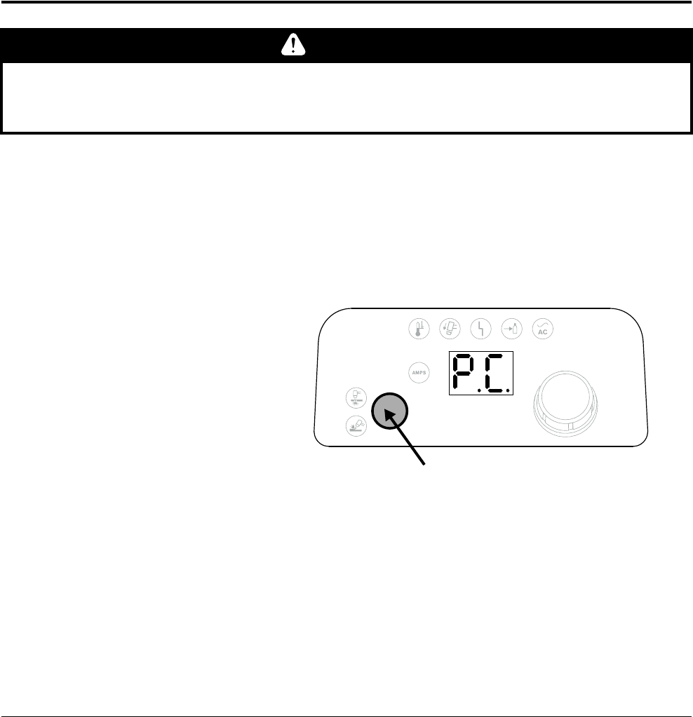
Troubleshooting Guide
10
Powermax45 XP Operator Manual 809240 157
Generator considerations
If a fault occurs while using a generator, turning the power switch quickly to OFF and then to
ON again (a quick restart) may not clear the fault. Instead, turn OFF the power supply and
wait 60 to 70 seconds before turning it ON again.
Issues with input line voltage (fault codes 0-13-0, 0-60-n, and 0-61-0) can be more difficult
to troubleshoot when you are operating the plasma system off of a generator. Disconnect
the plasma system from the generator, and connect it to an appropriately sized power outlet.
See page 36 for generator specifications.
Run a gas test
Use a gas test to determine if adequate gas pressure is exiting the torch. The gas test lets you see
the plasma system’s actual gas pressure so that you can compare it to the inlet set pressure.
Enter gas test mode
1. Make sure the correct mode is selected for the process you want to validate (Cut or
Gouge/Marking).
2. Press-and-hold the Mode
button for approximately
5seconds.
3. Release the Mode button
when the 2-digit display
shows P.C.
P.C. indicates
pressure check.
CAUTION
Point the torch away from you before performing a gas test. Always keep hands, clothes, and
objects clear of the torch tip. Never point the torch toward yourself or others.
Press-and-hold for 5 seconds.
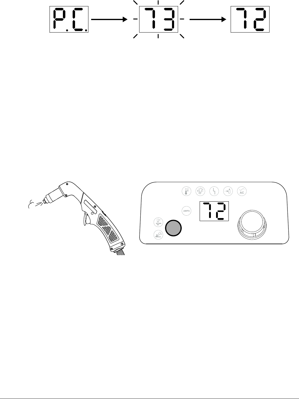
Troubleshooting Guide
10
158 809240 Operator Manual Powermax45 XP
4. The set pressure blinks on the 2-digit display before the actual output gas pressure displays.
Make note of the set pressure so that you can compare it to the actual pressure.
If the 2-digit display shows “0.0” (bar) or “00” (psi) when you enter gas
test mode, the torch is not in a “ready to fire” state. In this case, pull the
trigger (hand torches) or initiate a start signal (machine torches). The
system then emits the warning puffs of air (see page 47) and displays the
actual pressure.
While gas test mode is active
Air flows continuously from the torch tip.
The 2-digit display shows the output gas pressure (in psi or bar – see page 59).
The AMPS LED remains off.
Exit gas test mode
You can do either of the following actions to exit gas test mode:
Press the Mode button.
Turn the adjustment knob.
“P.C.” displays when you enter
gas test mode.
The actual pressure displays.The set pressure blinks briefly.
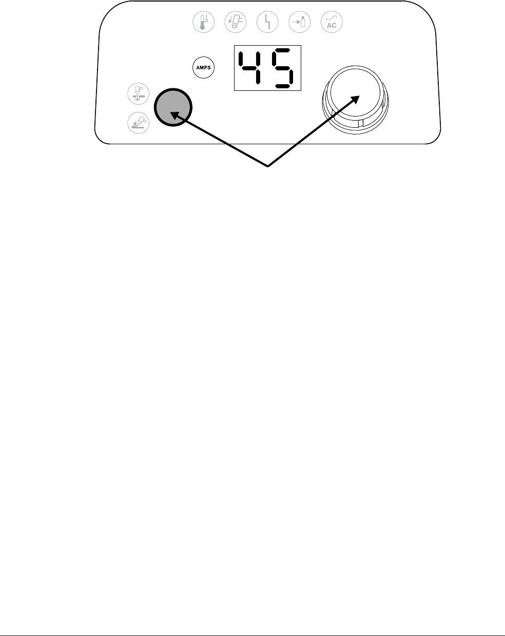
Troubleshooting Guide
10
Powermax45 XP Operator Manual 809240 159
After the system exits gas test mode:
The 2-digit display shows the cutting current (amperage).
The AMPS LED illuminates.
Press button or turn knob to exit gas test mode.

Troubleshooting Guide
10
160 809240 Operator Manual Powermax45 XP
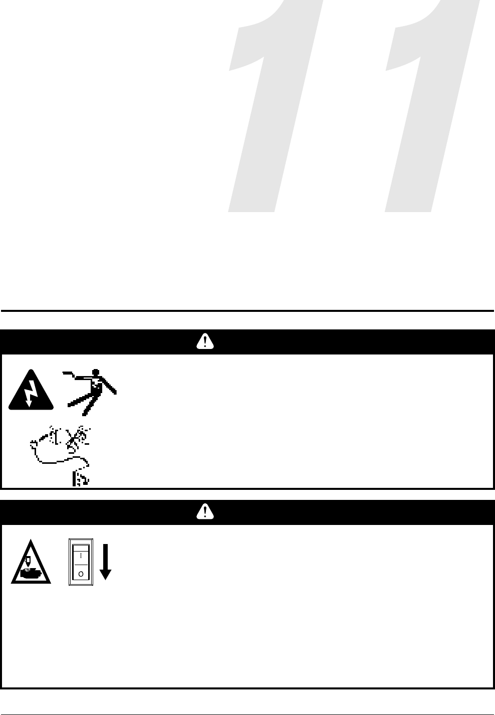
Powermax45 XP Operator Manual 809240 161
Routine Maintenance
Inspect the system and torch
WARNING
ELECTRIC SHOCK CAN KILL
Disconnect electric power before performing any maintenance.
All work requiring removal of the power supply cover must be performed
by a qualified technician.
See the Safety and Compliance Manual (80669C) for more safety
precautions.
WARNING
INSTANT-ON TORCHES – PLASMA ARC CAN CAUSE INJURY, BURNS
The plasma arc ignites immediately when you pull the torch trigger.
Before changing consumables, one of the following actions must be
taken. Whenever possible, complete the first action.
Turn OFF (O) the plasma power supply.
OR
Move the torch-disable switch to the yellow lock (X) position
(closest to the torch lead). Pull the trigger to make sure the
torch does not fire a plasma arc.
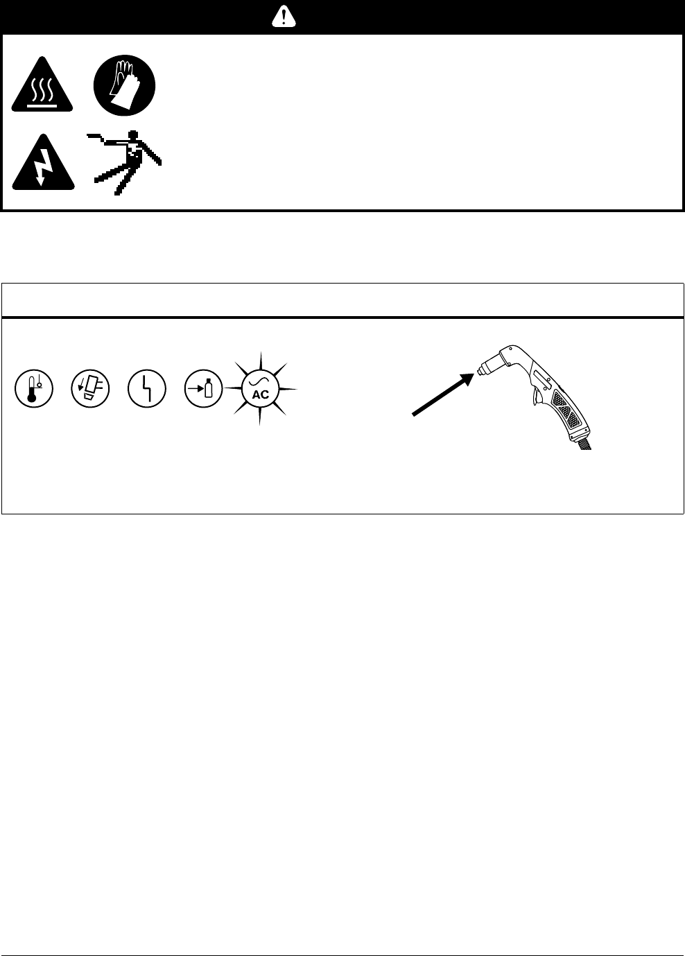
Routine Maintenance
11
162 809240 Operator Manual Powermax45 XP
Every use
WARNING
RISK OF BURNS AND ELECTRIC SHOCK – WEAR INSULATED GLOVES
Always wear insulated gloves when changing the consumables. The
consumables get very hot during cutting and can cause severe burns.
Touching the consumables can also result in electric shock if the power
supply in ON and the torch-disable switch is not in the yellow lock (X)
position.
System Torch
Check the indicator LED lights and correct
any fault conditions. See page 151.
Inspect the consumables for proper
installation and wear. See page 165.
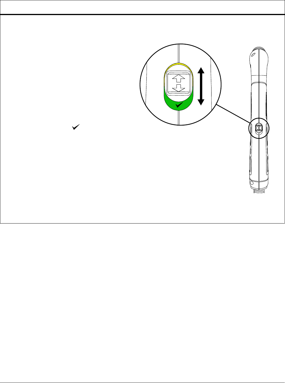
Routine Maintenance
11
Powermax45 XP Operator Manual 809240 163
Every consumable change or weekly (whichever is more frequent)
Torch
Test the torch-disable switch to make sure it
properly disables and activates the torch:
1. With the plasma power supply turned
ON, set the torch-disable switch to the
yellow lock (X) position.
2. Point the torch away from yourself and
others. Pull the trigger to make sure that
the torch does not fire an arc. For the
machine torch, run a START/STOP
command from the CNC.
3. Set the torch-disable switch to the
green “ready to fire” ( ) position.
4. Point the torch away from yourself and
others. Pull the trigger 1 time. For the
machine torch, run a START/STOP
command from the CNC. Make sure
that the torch does not fire an arc. Make
sure that instead the torch emits
multiple puffs of air in quick succession.
Seepage47.
Replace the torch-disable switch if it is not
working properly. See page 171.
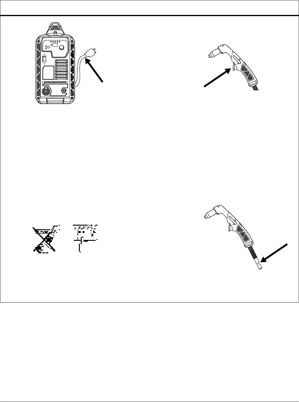
Routine Maintenance
11
164 809240 Operator Manual Powermax45 XP
Every 3 months
System Torch
Inspect the power cord and plug.
Replace if damaged. See page 173.
Hand torches: inspect the trigger for
damage.
Hand and machine torches: inspect the
torch body for cracks and exposed wires.
Replace any damaged parts.
Seepage171.
Replace any damaged labels.
Seepage181.
Inspect the torch lead. Replace if damaged.
Seepage171.
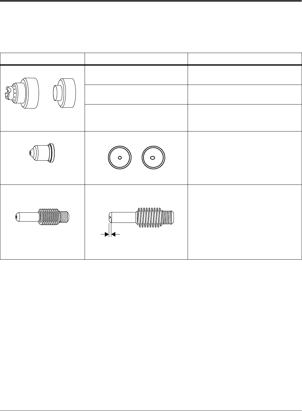
Routine Maintenance
11
Powermax45 XP Operator Manual 809240 165
Inspect the consumables
The best way to judge the condition of used consumables is to regularly check the cut edge quality
of the metal. When the cut quality begins to deteriorate, inspect the consumables.
Many common cut issues can be resolved by installing new consumables in the torch. See page 48.
Part Inspect Action
Shield
Deflector
Shield: The center hole for
roundness.
Shield: Replace the shield if the center
hole is no longer round.
Deflector: The edges of the center
hole for damage or noticeable wear.
Deflector: Replace the deflector is the
center hole is worn or damaged.
The gap between the nozzle and the
shield or deflector for accumulated
debris.
Remove the shield or deflector and clean
away any debris.
Nozzle
The center hole for roundness. Replace the nozzle if the center hole is
not round.
Replace the nozzle and the electrode
together.
Electrode
The center surface for wear, and
verify the pit depth.
Replace the electrode if the surface is
severely worn or the pit depth is greater
than 1 mm (0.04 inch) deep.
Replace the nozzle and the electrode
together.
For more information about how to
measure electrode pit depth, refer to
How to measure the pit depth of an
electrode on page 166.
Good
Worn
Maximum 1 mm
(0.04 inch)
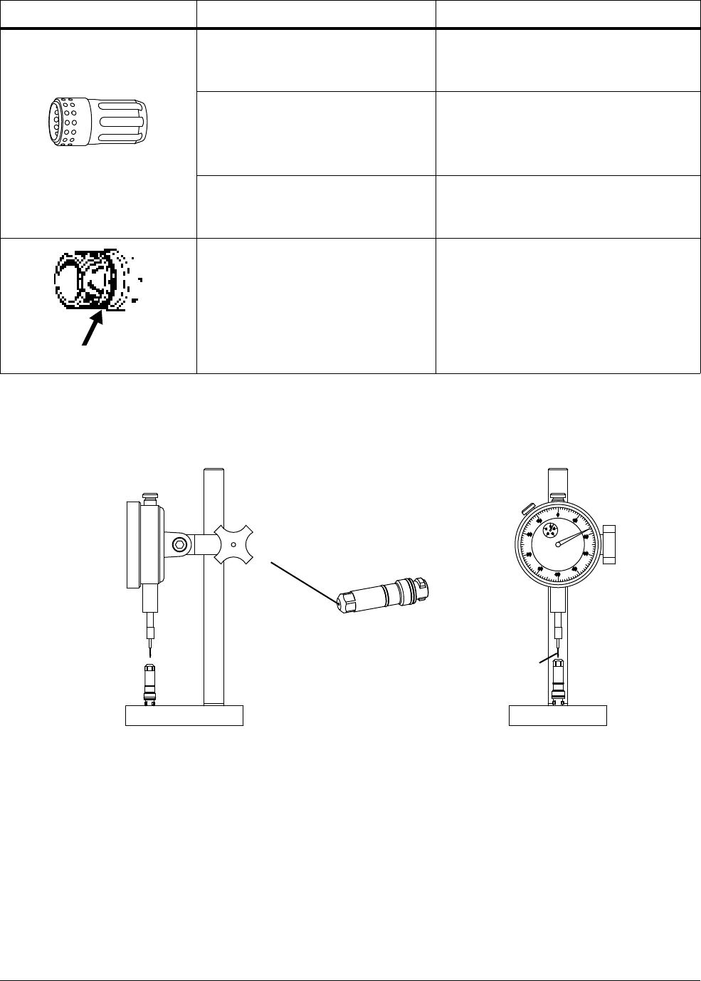
Routine Maintenance
11
166 809240 Operator Manual Powermax45 XP
How to measure the pit depth of an electrode
Use an electrode pit-depth gauge to measure the pit depth on the electrode.
A pit-depth gauge (004630) is available from Hypertherm. See Accessory
parts on page 180.
Swirl ring
The surface inside the swirl ring for
damage or wear and the gas holes
for blockages.
Replace the swirl ring if the surface is
damaged or worn or any of the gas holes
are blocked.
The O-ring inside the swirl ring for
damage or wear.
If the O-ring in the swirl ring is cracked,
worn, or damaged, replace the swirl ring.
Do not apply grease or other lubricants
to the O-ring in the swirl ring.
The length of the swirl ring. If the length of the 220857 or 220947
swirl ring is less than 30.5 mm
(1.2 inches), replace it.
Torch O -ri n g
The surface for damage, wear, or a
lack of lubrication.
If the torch O-ring is dry, apply a thin film
of silicone lubricant on the O-ring and
the threads. The O-ring should look
shiny, but there should not be any excess
or built-up lubricant.
If the O-ring is cracked or worn, replace
it.
Part Inspect Action
10
0
20
40
30
4
0
2
3
1
80
60
70
50
90
Electrode
(not to scale)
Pit
Replace gauge point (004629) if damaged
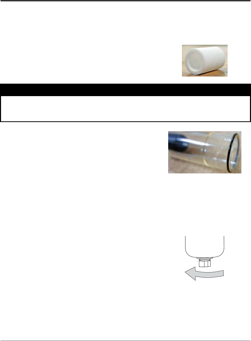
Routine Maintenance
11
Powermax45 XP Operator Manual 809240 167
Replace the air filter bowl and filter element
It is extremely important to maintain a clean, dry gas supply line in order to:
Prevent oil, water, dirt, and other contaminants from damaging internal components.
Achieve optimal cut quality and consumable life.
Check the filter element inside the air filter bowl regularly,
especially in environments that are very dusty or very warm
and humid. Replace the filter element when it is dirty or
starts to deteriorate. See page 173 for part numbers.
Keep the filter bowl and O-ring free from oil, chemicals, dirt,
and other contaminants. These contaminants can prevent a
good seal, causing gas to leak and additional contaminants
to go through the gas line in the power supply and torch.
Over time, these contaminants can damage internal
components.
If you are using an external filtration
system – such as the Eliminizer filter kit
(128647) – also check that filter regularly for required maintenance or
cleaning.
You may see a small amount of water in the bottom of the filter bowl. The filter bowl automatically
purges excess moisture when enough water accumulates to engage the float mechanism inside the
bowl.
To manually drain water from the bowl, unscrew the nut at
the bottom of the bowl by hand. To avoid damaging the
plastic nut, do not use a wrench or other tool.
NOTICE
Synthetic lubricants containing esters that are used in some air compressors will damage
polycarbonates used in the air filter bowl.
Unscrew nut to remove
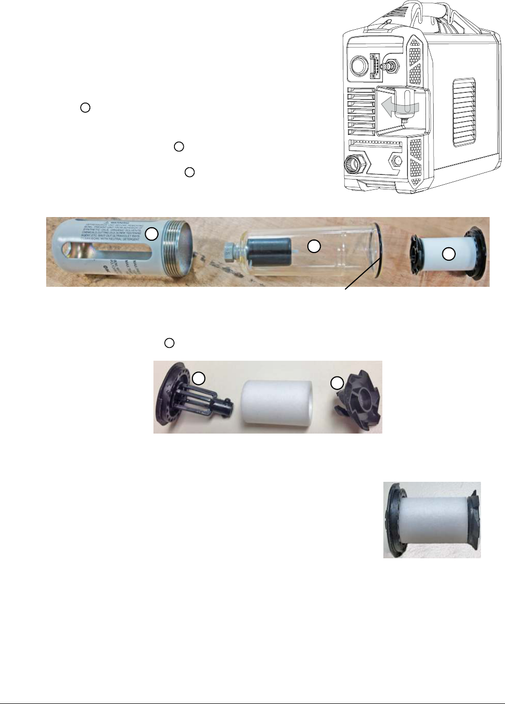
Routine Maintenance
11
168 809240 Operator Manual Powermax45 XP
1. Set the power switch on the power supply to
OFF (O). Disconnect the power cord from the
power source.
2. Disconnect the gas supply from the back of the
power supply.
3. Remove the air filter bowl by unscrewing the metal
guard until it detaches from the air filter
assembly inside the power supply.
4. Remove the air filter bowl from the metal guard.
5. Gently pry the filter element out of the filter
bowl. Be careful not to damage the O-ring at the
top of the bowl.
6. Twist the plastic fittings until they come apart, approximately a 1/4 turn. Set the fittings aside.
7. Enclose the new air filter element in the plastic fittings.
Twist the plastic fittings until they lock together,
approximately a 1/4 turn.
1
2
3
1
2
3
O-ring
4
4
4
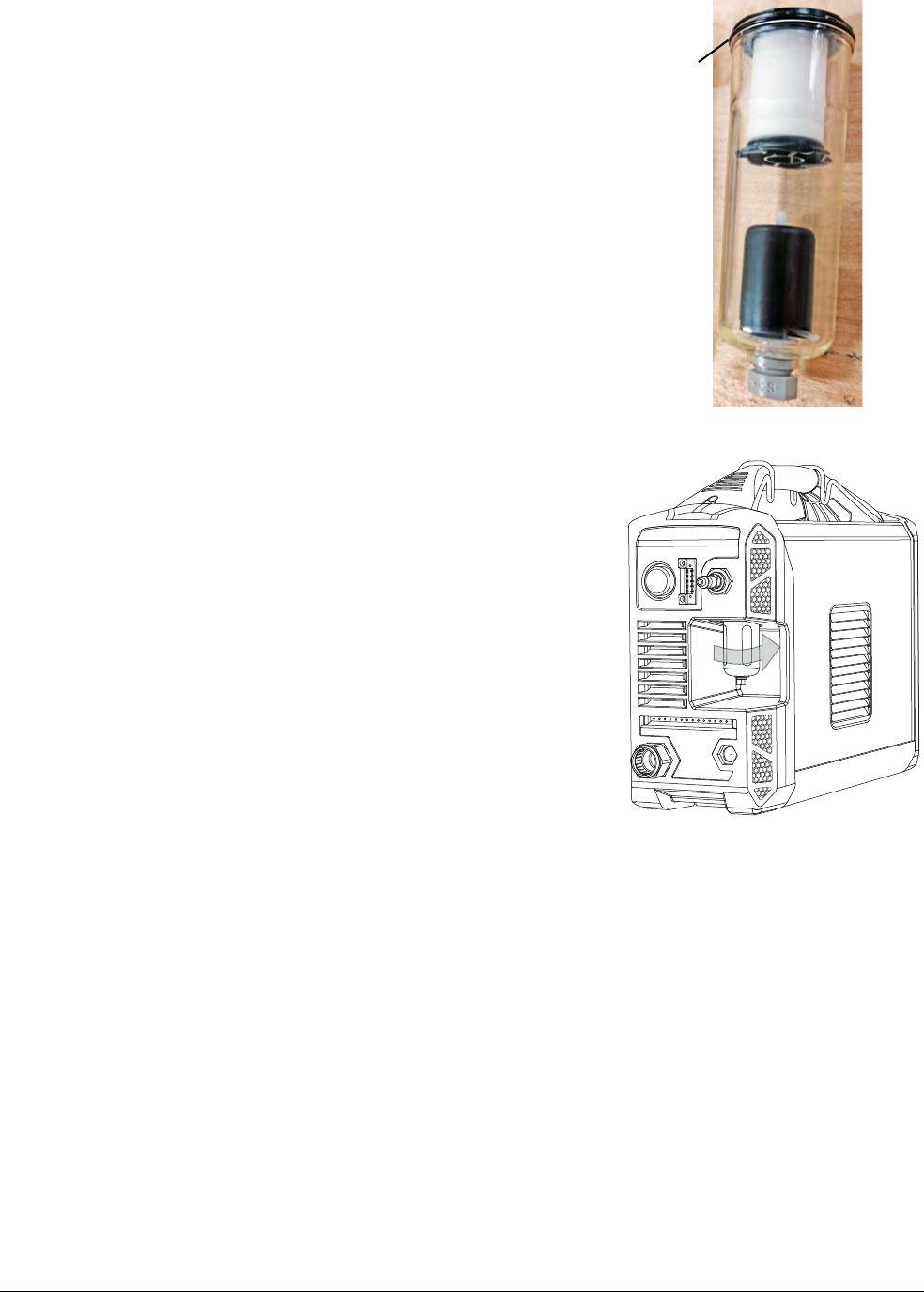
Routine Maintenance
11
Powermax45 XP Operator Manual 809240 169
8. Clean the air filter bowl by wiping away any oil, dirt, or
other contaminants.
A yellow residue on the filter bowl often indicates
that oil is getting into the gas supply line.
9. Examine the O-ring. Replace it if it is cracked or
damaged. Place the O-ring at the top of the filter bowl.
10. Place the filter element inside the air filter bowl. Press
down on the top plastic fitting until you hear it snap into
place.
11 . Place the air filter bowl inside the metal guard.
12. Put the air filter bowl back into place by screwing the
metal guard into the air filter assembly that is inside the
power supply.
Make sure the air filter bowl and metal guard
remain straight as you install them. Otherwise,
you may damage the threads on the metal guard.
13. Reconnect the gas supply to the back of the power
supply.
14. Reconnect the power cord, and set the power switch to
ON (I).
O-ring

Routine Maintenance
11
170 809240 Operator Manual Powermax45 XP

Powermax45 XP Operator Manual 809240 171
Replacement Parts and Accessories
Use the part numbers and kit numbers in this section to order replacement parts and accessories
for your plasma power supply and torches.
For consumable part numbers:
Hand torch cutting and piercing: see page 63
Gouging: see page 75
Machine torch cutting and piercing: see page 111
Marking: see page 119
For instructions on installing the consumables, see Step 1 – Install
consumables and activate torch on page 48.
For assistance with repairing or replacing internal components:
1. Call your Hypertherm distributor or authorized Hypertherm repair facility.
2. Call the nearest Hypertherm office listed in the front of this manual.
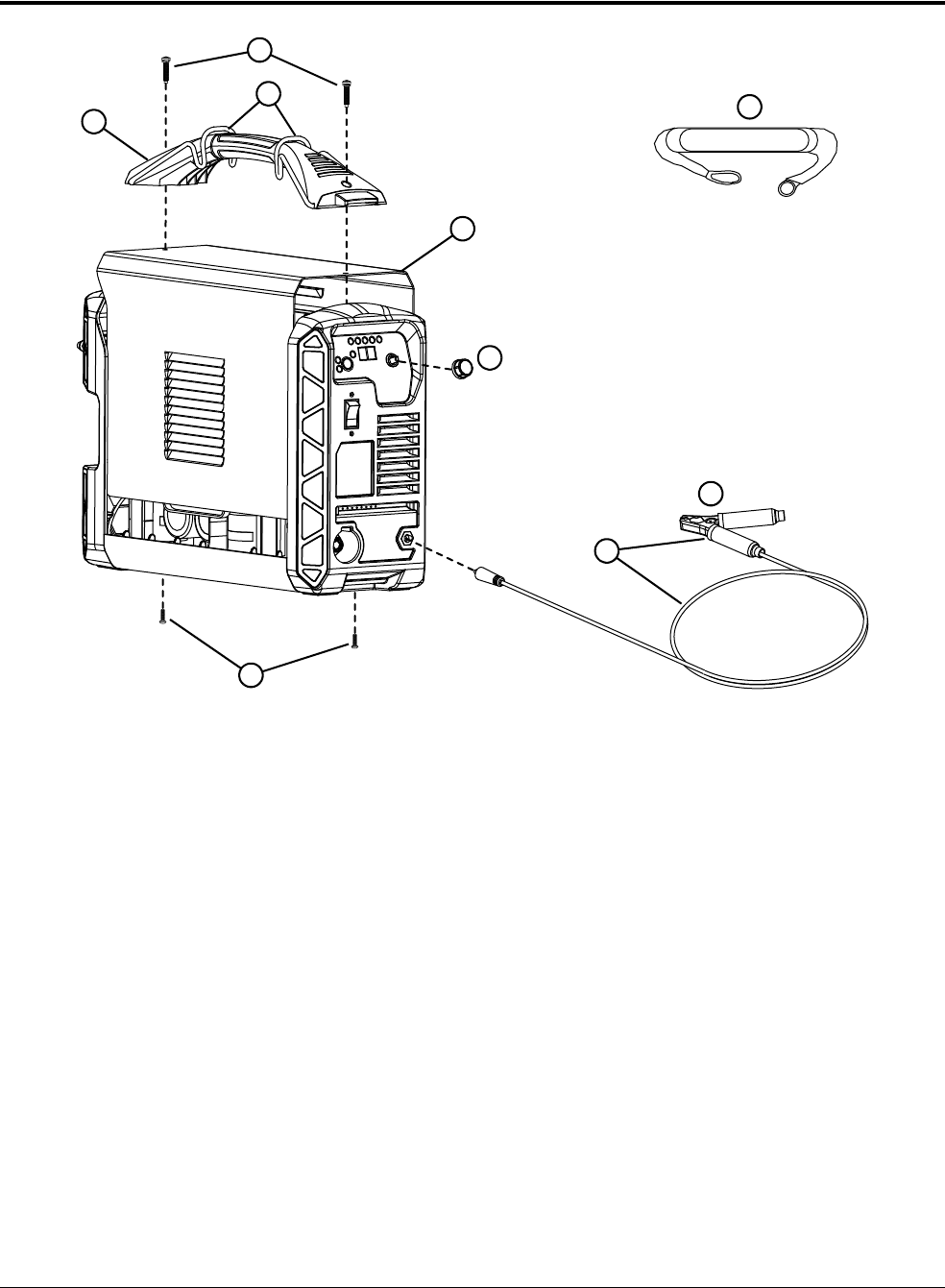
Replacement Parts and Accessories
12
172 809240 Operator Manual Powermax45 XP
Plasma supply exterior, front
Item Kit number Description
1 428663 Kit: Power supply handle with screws (includes clips for shoulder straps)
2 104821 Replacement clips for shoulder strap*
3 428662 Kit: Replacement screws for power supply handle, front panel, and rear panel
4 428657 Kit: Power supply cover with labels, CSA (no screws included)
4 428658 Kit: Power supply cover with labels, CE/CCC (no screws included)
5 428143 Kit: Adjustment knob for control panel
6 223595 Work lead, 7.6 m (25 foot), with work clamp
6 223596 Work lead, 15 m (50 foot), with work clamp
7 228561 Kit: Work clamp, 200 A
8 127217 Shoulder strap (sold separately – not included with system)
* The clips for the shoulder strap come with the system. They are also included in the replacement kit for the power
supply handle. They do not come with the shoulder strap itself.
4
6
3
3
2
1
7
8
5
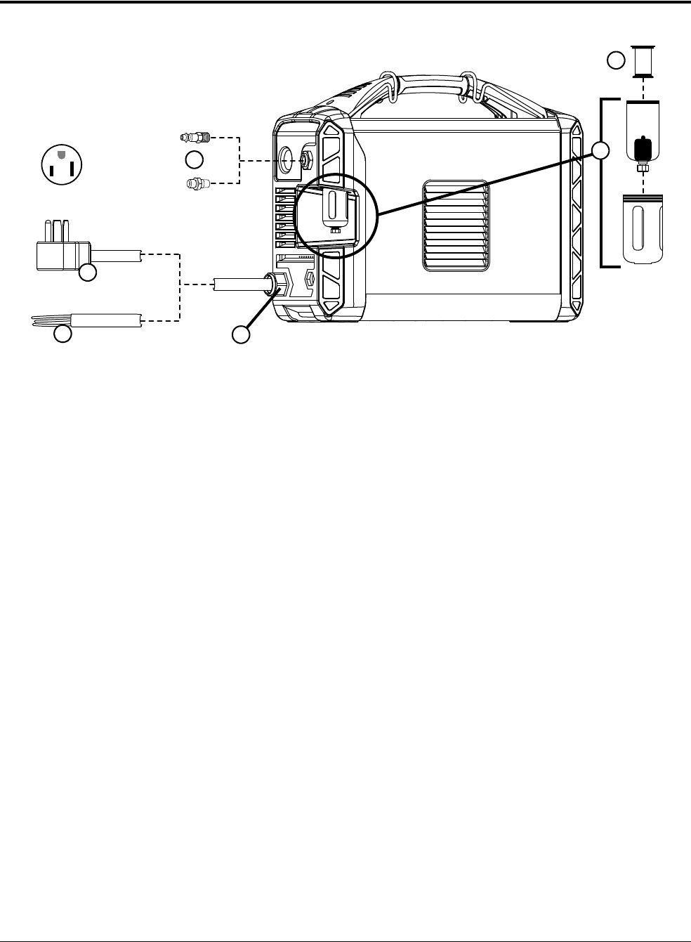
Replacement Parts and Accessories
12
Powermax45 XP Operator Manual 809240 173
Plasma supply exterior, rear
See page 167 for instructions on replacing the air filter bowl and the filter
element.
Item Kit number Description
1 428685 Kit: Gas inlet fittings:
• Industrial interchange quick-disconnect nipple with 1/4 NPT threads
• British Pipe Thread adapter G-1/4 BSPP with 1/4 NPT threads
2 428664 Kit: CSA power cord with strain relief, 1-phase, 3 m (10 foot) (includes NEMA 6-50P
power plug)
3 428667 Kit: CE/CCC power cord with strain relief, 1-phase, 3 m (10 foot) (no power plug
included)
3 428665 Kit: CSA power cord with strain relief, 3-phase, 3.5 m (11 foot) (no power plug included)
3 428666 Kit: CE/CCC power cord with strain relief, 3-phase, 3 m (10 foot) (no power plug
included)
4 228680 Kit: Strain relief for power cords
5 428673 Kit: Air filter bowl (polycarbonate) with metal guard (air filter element sold separately)
6 428378 Kit: Air filter element
NEMA 6-50P
1
2
3
5
4
6
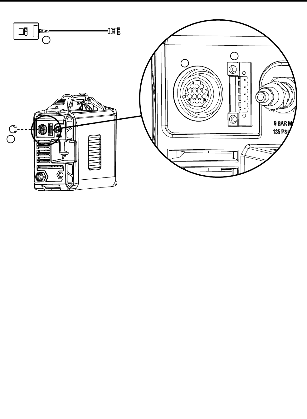
Replacement Parts and Accessories
12
174 809240 Operator Manual Powermax45 XP
Machine interface (CPC) and serial interface upgrade kits
The remote start pendant connects to the CPC port.
Item Kit number Description
1 428653 Kit: Machine interface (CPC) port with internal cables and voltage divider board (does not
include cover for receptacle)
2 428654 Kit: Serial interface port with internal cables and RS-485 board
3 127204 Cover for machine interface (CPC) port
4 128650 Remote start pendant for machine torch, 7.6 m (25 feet)
4 128651 Remote start pendant for machine torch, 15 m (50 feet)
4 128652 Remote start pendant for machine torch, 23 m (75 feet)
4 428755 Remote start pendant for machine torch, 45 m (150 feet)
3
4
1
2

Replacement Parts and Accessories
12
Powermax45 XP Operator Manual 809240 175
External cables for machine interface port and serial port
Hypertherm offers a variety of external cables that connect to the machine interface (CPC) port and
the serial port. For pictures and for setup information, see:
Connect the machine interface cable on page 102
Connect an optional RS-485 serial interface cable on page 109
Part number Description
023206 External machine interface cable (start, stop, arc transfer signals), 7.6 m (25 feet),
spade connectors
023279 External machine interface cable (start, stop, arc transfer signals), 15 m (50 feet),
spade connectors
228350 Kit: External machine interface cable (start, stop, arc transfer, and divided arc voltage
signals), 7.6 m (25 feet), spade connectors
228351 Kit: External machine interface cable (start, stop, arc transfer, and divided arc voltage
signals), 15 m (50 feet), spade connectors
223354 External machine interface cable (start, stop, arc transfer, and divided arc voltage signals),
3.0 m (10 feet), D-sub connector with screws
223355 External machine interface cable (start, stop, arc transfer, and divided arc voltage signals),
6.1 m (20 feet), D-sub connector with screws
223048 External machine interface cable (start, stop, arc transfer, and divided arc voltage signals),
7.6 m (25 feet), D-sub connector with screws
223356 External machine interface cable (start, stop, arc transfer, and divided arc voltage signals),
10.7 m (35 feet), D-sub connector with screws
123896 External machine interface cable (start, stop, arc transfer, and divided arc voltage signals),
15 m (50 feet), D-sub connector with screws
223733 External machine interface cable for PlasmaCAM
®
tables, 4.6m (15feet)
223734 External machine interface cable for PlasmaCAM tables, 6.1 m (20 feet)
223236 External RS-485 cable, unterminated, 7.6 m (25 feet)
223237 External RS-485 cable, unterminated, 15 m (50 feet)
223239 External RS-485 cable, 9-pin D-sub connector for Hypertherm controls, 7.6 m (25 feet)
223240 External RS-485 cable, 9-pin D-sub connector for Hypertherm controls, 15 m (50 feet)
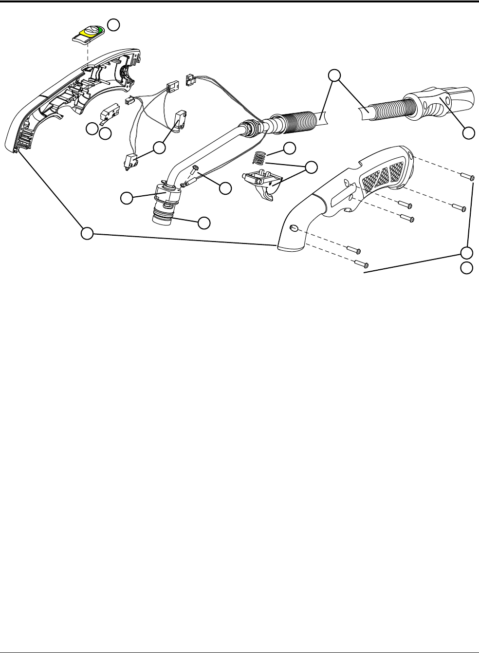
Replacement Parts and Accessories
12
176 809240 Operator Manual Powermax45 XP
75° hand torch replacement parts
* The torch assembly does not include consumables. See page 63 (cutting) and page 75 (gouging) for
consumable part numbers.
Item Kit number Description
088164* 75° hand torch assembly with 6.1 m (20 foot) lead
088165* 75° hand torch assembly with 15 m (50 foot) lead
1 428590 Kit: 75° hand torch handle (with screws)
2 428162 Kit: Hand torch start switch
3 428594 Kit: Cap-sensor switch and torch-disable switch assembly for hand torch (includes wires
and connectors)
4 428588 Kit: 75° hand torch main body (with O-ring)
5 428180 Kit: Replacement O-rings for torch body
6 075504 Pilot terminal screw
7 428156 Kit: Hand torch trigger and spring – includes start switch and screws for torch handle
8 428182 Kit: Replacement springs for hand torch trigger
9 428148 Kit: Replacement screws for torch handle
10 228314 Kit: Torch quick-disconnect repair (shell with button – does not include torch lead or
connector)
11 428592 Kit: Hand torch lead replacement, 6.1 m (20 foot)
11 428593 Kit: Hand torch lead replacement, 15 m (50 foot)
12 428595 Kit: Torch-disable slider for hand torch (with yellow/green label)
2
3
5
8
9
4
11
12
10
6
7
7
7
1
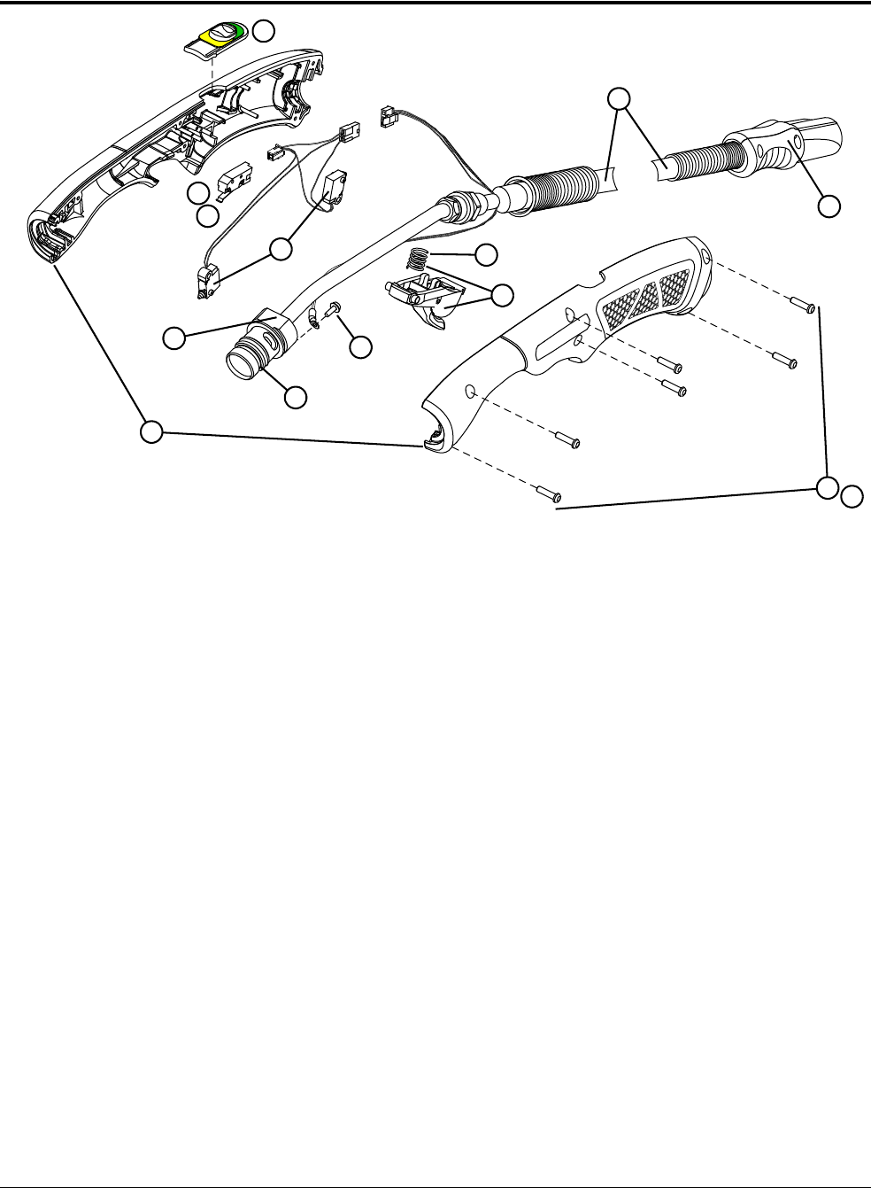
Replacement Parts and Accessories
12
Powermax45 XP Operator Manual 809240 177
15° hand torch replacement parts
* The torch assembly does not include consumables. See page 63 (cutting) and page 75 (gouging) for
consumable part numbers.
Item Kit number Description
088162* 15° hand torch assembly with 6.1m (20foot) lead
088163* 15° hand torch assembly with 15 m (50 foot) lead
1 428591 Kit: 15° hand torch handle (with screws)
2 428162 Kit: Hand torch start switch
3 428594 Kit: Cap-sensor switch and torch-disable switch assembly for hand torch (includes wires
and connectors)
4 428589 Kit: 15° hand torch main body (with O-ring)
5 428180 Kit: Replacement O-rings for torch body
6 075504 Pilot terminal screw
7 428156 Kit: Hand torch trigger and spring – includes start switch and screws for torch handle
8 428182 Kit: Replacement springs for hand torch trigger
9 428148 Kit: Replacement screws for torch handle
10 228314 Kit: Torch quick-disconnect repair (shell with button – does not include torch lead or
connector)
11 428592 Kit: Hand torch lead replacement, 6.1 m (20 foot)
11 428593 Kit: Hand torch lead replacement, 15 m (50 foot)
12 428595 Kit: Torch-disable slider for hand torch (with yellow/green label)
12
2
3
4
5
8
9
11
6
7
7
10
7
1
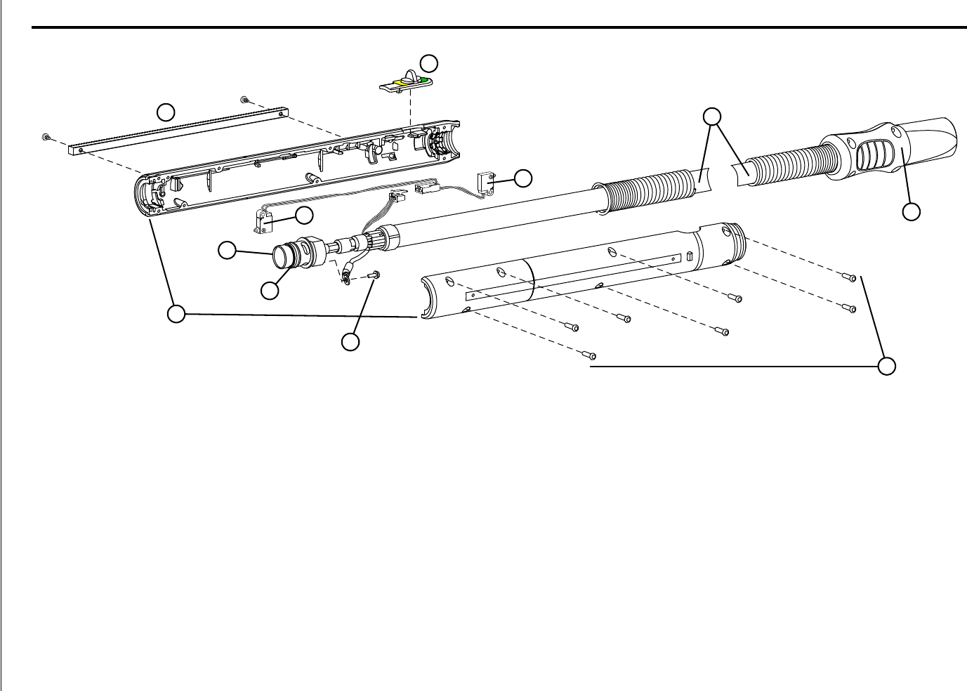
Replacement Parts and Accessories
12
178 809240 Operator Manual Powermax45 XP
Machine torch replacement parts
Item Kit number Description
088167* Kit: Machine torch assembly with 7.6 m (25 foot) lead
088168* Kit: Machine torch assembly with 10.7 m (35 foot) lead
088169* Kit: Machine torch assembly with 15 m (50 foot) lead
1 428703 Kit: Removable 32-pitch gear rack (with screws)
2 428596 Kit: Machine torch shell (with screws)
3 428704 Kit: Torch main body replacement for machine torch
4 428180 Kit: Replacement O-rings for torch body
5 075504 Pilot terminal screw
6 428148 Kit: Replacement screws for torch shell
1
3
4
5
6
7
9
10
8
9
2

Replacement Parts and Accessories
12
Powermax45 XP Operator Manual 809240 179
* The torch assembly does not include consumables. See page 111 (cutting), page 75 (gouging), and page 119 (marking) for consumable part numbers.
7 428260 Kit: Torch quick-disconnect repair (shell with button – does not include torch lead or connector)
8 428699 Kit: Machine torch lead replacement, 7.6 m (25 foot)
8 428710 Kit: Machine torch lead replacement, 10.7 m (35 foot)
8 428700 Kit: Machine torch lead replacement, 15 m (50 foot)
9 428705 Kit: Cap-sensor switch and torch-disable switch assembly for machine torch (includes wires and connector)
10 428706 Kit: Torch-disable slider for machine torch (with yellow/green label)
Item Kit number Description

Replacement Parts and Accessories
12
180 809240 Operator Manual Powermax45 XP
Accessory parts
Part number Description
128647 Eliminizer air filter kit (for moisture removal)
011092 Replacement filter element for Eliminizer air filter
428719 Oil removal coalescing filter kit
428720 Replacement filter element for oil removal coalescing filter
428718 Mounting bracket for Eliminizer air filter or oil removal coalescing filter
127217 Shoulder strap (clips not included)
104821 Replacement clips for shoulder strap*
127169 Leather cutting gloves
127239 Face shield, shade 6 lens
127219 Dust cover for power supply
017060 Rolling tool bag (fits power supply, torch, consumables, and some accessories)
024877 Leather torch lead cover, black with Hypertherm logo, 7.6 m (25 feet)
127102 Basic plasma (circle) cutting guide, maximum diameter 70 cm (28 inches)
027668 Deluxe plasma (circle) cutting guide, maximum diameter 51 cm (20 inches)
017059 Bevel cutting guide
027055 Silicone lubricant, 1/4 ounce (for O-ring on torch body and air filter bowl)
004630 Pit-depth gauge
004629 Pit-depth gauge point
* The clips for the shoulder strap come with the system. They are also included in the replacement kit for the power
supply handle. They do not come with the shoulder strap itself. See page 172.
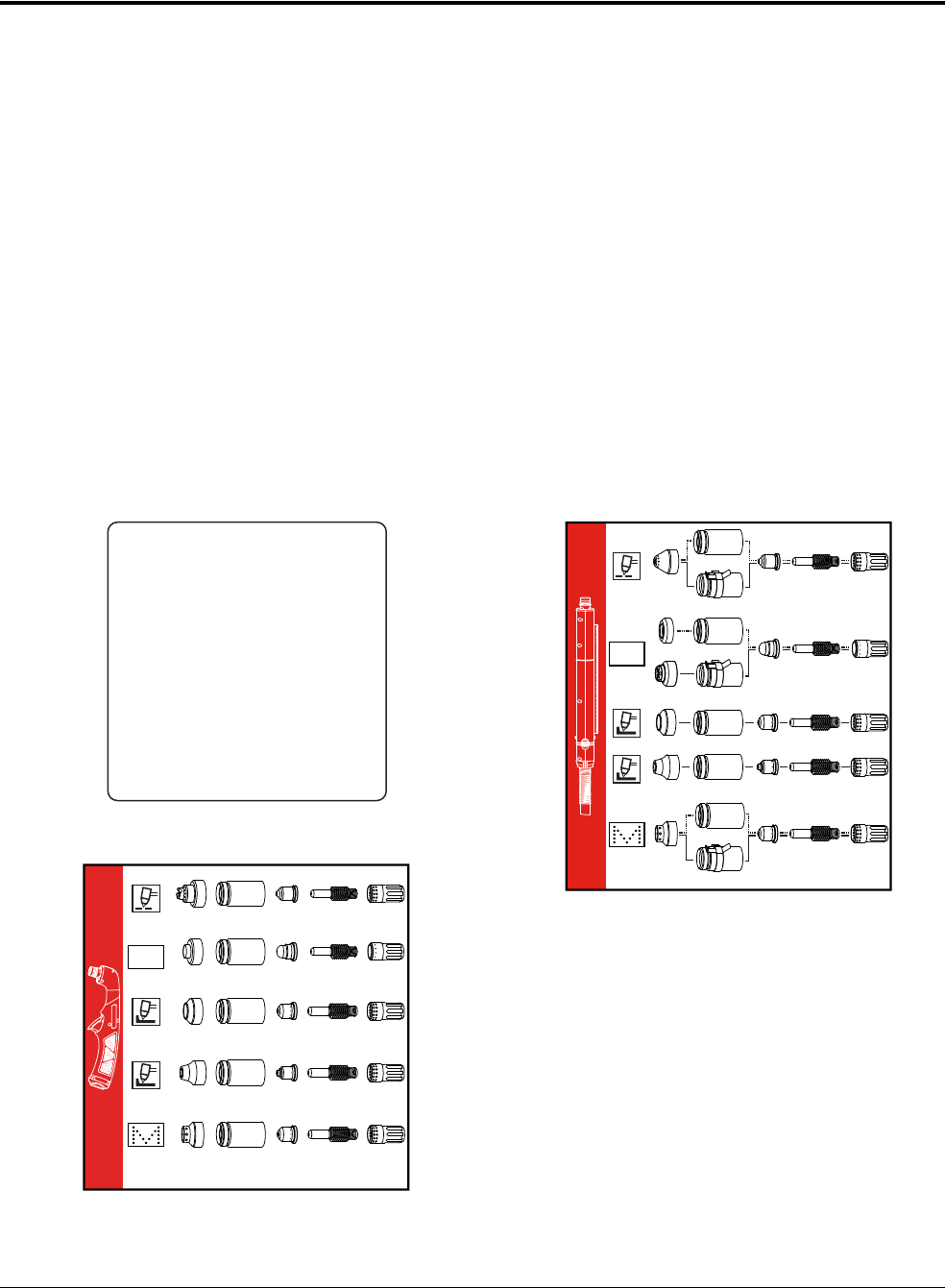
Replacement Parts and Accessories
12
Powermax45 XP Operator Manual 809240 181
Powermax45 XP Labels
The label kits include:
Warning labels
Decals for side panels
Consumable labels
Consumable labels and fault codes label
The consumable labels and the fault codes label are removable stickers. The fault codes label is
found inside the front cover of the Operator Manual. The consumable labels are included in the
literature package that comes with the system. Place the labels on the side of the power supply or
near your work area for ease of reference.
Kit number Description
428655 Kit: Powermax45 XP labels for 1-phase models
428656 Kit: Powermax45 XP labels for 3-phase models
220854
220857220817
220953
220941 220842
220953
220953
420414 220854
220854420480
420415
420419
220857220842
220857220842
420542
220854
420415 220857220842
220854220955
220930 220842
220948
FineCut
®
26-45 A
10-25 A
10-25 A
220947
See Operator Manual for details
Fault Codes
0-11-0 Invalid mode input from remote controller
0-11-1 Invalid current input from remote controller
0-11-2 Invalid pressure input from remote controller
0-12-1 Low output gas pressure: alert
0-12-2 High output gas pressure: alert
0-12-3 Output gas pressure unstable: alert
0-13-0 AC input unstable: alert
0-51-0 Start/trigger signal ON at power up
0-60-0 AC input voltage error – phase loss
0-60-1 AC input voltage error – voltage too low
0-60-2 AC input voltage error – voltage too high
0-61-0 AC input unstable: shutdown
Fault codes label
Consumable label – hand torch
420414 220854
220854420480
420415
420419
220857220842
220857220842
420542 220854 420415 220857220842
220854
220854 220857
220947
220818
220931 220930
220941
220842
220842
FineCut
®
26-45 A
10-25 A
10-25 A
Consumable label – machine torch
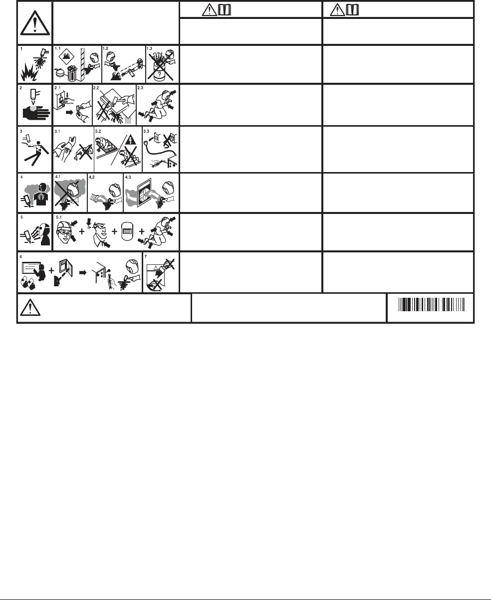
Replacement Parts and Accessories
12
182 809240 Operator Manual Powermax45 XP
CSA warning label
This warning label is affixed to some power supplies. It is important that the operator and
maintenance technician understand the intent of these warning symbols as described.
WARNING:
This product can expose you to chemicals including
lead and lead compounds, which are known to the State of
California to cause cancer and birth defects or other reproductive
harm. For more information go to www.p65warnings.ca.gov.
AVERTISSEMENT :
Ce produit peut vous exposer à des produits chimiques, dont
le plomb et des composés de plomb, reconnus par l’État de la Californie comme cause
de cancer et d’anomalie congénitale ou d’autres anomalies de l’appareil reproducteur.
Pour obtenir de plus amples renseignements, consultez le www.p65warnings.ca.gov.
Read and follow these instructions, employer safety
practices, and material safety data sheets. Refer to
ANS Z49.1, “Safety in Welding, Cutting and Allied
Processes” from American Welding Society
(http://www.aws.org) and OSHA Safety and Health
Standards, 29 CFR 1910 (http://www.osha.gov).
WARNING
1. Cutting sparks can cause explosion or fire.
1.1 Do not cut near flammables.
1.2 Have a fire extinguisher nearby and ready to use.
1.3 Do not use a drum or other closed container as a cutting
table.
2. Plasma arc can injure and burn; point the nozzle
away from yourself. Arc starts instantly when
triggered.
2.1 Turn off power before disassembling torch.
2.2 Do not grip the workpiece near the cutting path.
2.3 Wear complete body protection.
3. Hazardous voltage. Risk of electric shock or burn.
3.1 Wear insulating gloves. Replace gloves when wet or
damaged.
3.2 Protect from shock by insulating yourself from work and
ground.
3.3 Disconnect power before servicing. Do not touch live parts.
4. Plasma fumes can be hazardous.
4.1 Do not inhale fumes.
4.2 Use forced ventilation or local exhaust to remove the fumes.
4.3 Do not operate in closed spaces. Remove fumes with
ventilation.
6. Become trained.
Only qualified personnel should
operate this equipment. Use torches specified in the manual.
Keep non-qualified personnel and children away.
5. Arc rays can burn eyes and injure skin.
5.1 Wear correct and appropriate protective equipment to
protect head, eyes, ears, hands, and body. Button shirt
collar. Protect ears from noise. Use welding helmet with
the correct shade of filter.
7. Do not remove, destroy, or cover this label.
Replace if it is missing, damaged, or worn.
Plasma cutting can be injurious to operator and persons in the
work area. Consult manual before operating. Failure to follow
all these safety instructions can result in death.
AVERTISSEMENT
Le coupage plasma peut être préjudiciable pour l’opérateur
et les personnes qui se trouvent sur les lieux de travail.
Consulter le manuel avant de faire fonctionner. Le non respect
des ces instructions de sécurité peut entraîner la mort.
1. Les étincelles de coupage peuvent provoquer
une explosion ou un incendie.
1.1 Ne pas couper près des matières inflammables.
1.2 Un extincteur doit être à proximité et prêt à être utilisé.
1.3 Ne pas utiliser un fût ou un autre contenant fermé comme
table de coupage.
2. L’arc plasma peut blesser et brûler; éloigner
la buse de soi. Il s’allume instantanément
quand on l’amorce.
2.1 Couper l’alimentation avant de démonter la torche.
2.2 Ne pas saisir la pièce à couper de la trajectoire de coupage.
2.3 Se protéger entièrement le corps.
3. Tension dangereuse. Risque de choc électrique
ou de brûlure.
3.1 Porter des gants isolants. Remplacer les gants quand ils sont
humides ou endommagés.
3.2 Se protéger contre les chocs en s’isolant de la pièce et de
la terre.
3.3 Couper l’alimentation avant l’entretien. Ne pas toucher
les pièces sous tension.
4. Les fumées plasma peuvent être dangereuses.
4.1 Ne pas inhaler les fumées.
4.2 Utiliser une ventilation forcée ou un extracteur local pour
dissiper les fumées.
4.3 Ne pas couper dans des espaces clos. Chasser les fumées
par ventilation.
5. Les rayons d’arc peuvent brûler les yeux et
blesser la peau.
5.1 Porter un bon équipement de protection pour se protéger
la tête, les yeux, les oreilles, les mains et le corps. Boutonner
le col de la chemise. Protéger les oreilles contre le bruit. Utiliser
un masque de soudeur avec un filtre de nuance appropriée.
6. Suivre une formation.
Seul le personnel qualifié a
le droit de faire fonctionner cet équipement. Utiliser
exclusivement les torches indiquées dans le manual. Le
personnel non qualifié et les enfants doivent se tenir à l’écart.
7. Ne pas enlever, détruire ni couvrir cette étiquette.
La remplacer si elle est absente, endommagée ou usée.
(
110673 Rev F)
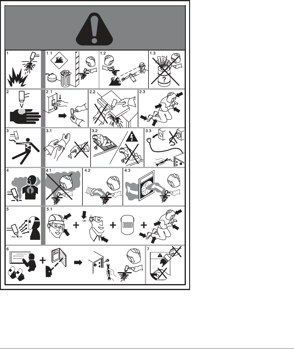
Replacement Parts and Accessories
12
Powermax45 XP Operator Manual 809240 183
CE/CCC warning label
This warning label is affixed to some power supplies. It is important that the
operator and maintenance technician understand the intent of these
warning symbols as described. The numbered text corresponds to the
numbered boxes on the label.
1. Cutting sparks can cause
explosion or fire.
1.1 Do not cut near flammables.
1.2 Have a fire extinguisher nearby
and ready to use.
1.3 Do not use a drum or other
closed container as a cutting
table.
2. Plasma arc can injure and burn;
point the nozzle away from
yourself. Arc starts instantly when
triggered.
2.1 Turn off power before
disassembling torch.
2.2 Do not grip the workpiece near
the cutting path.
2.3 Wear complete body protection.
3. Hazardous voltage. Risk of
electric shock or burn.
3.1 Wear insulating gloves. Replace
gloves when wet or damaged.
3.2 Protect from shock by insulating
yourself from work and ground.
3.3 Disconnect power before
servicing. Do not touch live parts.
4. Plasma fumes can be hazardous.
4.1 Do not inhale fumes.
4.2 Use forced ventilation or local
exhaust to remove the fumes.
4.3 Do not operate in closed spaces.
Remove fumes with ventilation.
5. Arc rays can burn eyes and injure
skin.
5.1 Wear correct and appropriate
protective equipment to protect
head, eyes, ears, hands, and
body. Button shirt collar. Protect
ears from noise. Use welding
helmet with the correct shade of
filter.
6. Become trained. Only qualified
personnel should operate this
equipment. Use torches specified
in the manual. Keep non-qualified
personnel and children away.
7. Do not remove, destroy, or cover
this label. Replace if it is missing,
damaged, or worn.
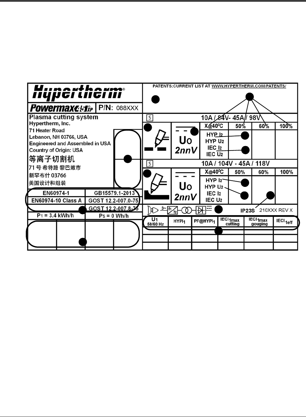
Replacement Parts and Accessories
12
184 809240 Operator Manual Powermax45 XP
Data plate
The data plate on the bottom of the plasma power supply contains 2 sets of ratings:
The HYP ratings are Hypertherm power supply ratings. They reflect the capability of the
system based on Hypertherm’s internal testing.
The IEC ratings are predefined minimum thresholds that the system was required to meet to
fulfill IEC standard 60974-1.
CSA and CE/CCC data plates differ slightly. The following sample is a CE/CCC data plate.
1
3
4
5
6
8
9
12
1
0
2
7
11
14
13
3
1 Placeholder for barcode, date of manufacture,
and serial number
2 Region-specific certification standards
3 Placeholders for region-specific certification
symbols – see Symbols and marks on
page 185
4 Symbol for plasma cutting
5 Symbol for plasma gouging
6 U
0
= Rated no load voltage (V)
7 X = Duty cycle (%)
8 HYP = Hypertherm internal rating
9 IEC = International Electrotechnical
Commission rating
10 I
2
= Conventional welding current (A)
11 U
2
= Conventional welding voltage (V)
12 Symbol for inverter-based power source
(1-phase or 3-phase)
13 Ingress Protection (IP) rating
14 U
1
= Input voltage (V)
I
1
= Input current (A)
PF = Power factor

Replacement Parts and Accessories
12
Powermax45 XP Operator Manual 809240 185
Symbols and marks
Your product may have one or more of the following marks on or near the data plate. Because of differences
and conflicts in national regulations, not all marks are applied to every version of a product.
S mark
The S mark indicates that the power supply and torch are suitable for operations carried out in
environments with increased hazard of electrical shock according to IEC 60974-1.
CSA mark
Products with a CSA mark meet the United States and Canadian regulations for product safety.
The products were evaluated, tested, and certified by CSA-International. Alternatively, the product
may have a mark by one of the other Nationally Recognized Testing Laboratories (NRTL)
accredited in both the United States and Canada, such as UL or TÜV.
CE mark
The CE marking signifies the manufacturer’s declaration of conformity to applicable European
directives and standards. Only those versions of products with a CE marking located on or near
the data plate comply with European Directives. Applicable directives may include the European
Low Voltage Directive, the European Electromagnetic Compatibility (EMC) Directive, the Radio
Equipment Directive (RED), and the Restriction of Hazardous Substances (RoHS) Directive.
See the European CE Declaration of Conformity for details.
Eurasian Customs Union (CU) mark
CE versions of products that include an EAC mark of conformity meet the product safety and
EMC requirements for export to Russia, Belarus, and Kazakhstan.
GOST-TR mark
CE versions of products that include a GOST-TR mark of conformity meet the product safety and
EMC requirements for export to the Russian Federation.
RCM mark
CE versions of products with a RCM mark comply with the EMC and safety regulations required
for sale in Australia and New Zealand.
CCC mark
The China Compulsory Certification (CCC) mark indicates that the product has been tested and
found compliant with product safety regulations required for sale in China.
UkrSEPRO mark
The CE versions of products that include a UkrSEPRO mark of conformity meet the product safety
and EMC requirements for export to the Ukraine.
Serbian AAA mark
CE versions of products that include a AAA Serbian mark meet the product safety and
EMC requirements for export to Serbia.
RoHS mark
The RoHS mark indicates that the product meets the requirements of the European Restriction of
Hazardous Substances (RoHS) Directive.
s

Replacement Parts and Accessories
12
186 809240 Operator Manual Powermax45 XP
IEC symbols
The following symbols may appear on the data plate, control labels, and switches. For information
on the front panel LEDs, see Controls and indicators on page 43.
Direct current (DC)
Alternating current (AC)
Plasma torch cutting
Gouging
AC input power
connection
The terminal for the
external protective (earth)
conductor
I Power is ON
O Power is OFF
A 1-phase or 3-phase
inverter-based power
source
Volt/amperage curve,
“drooping” characteristic
f
1
f
2
1~
